- LRO Mission Overview

Содержание
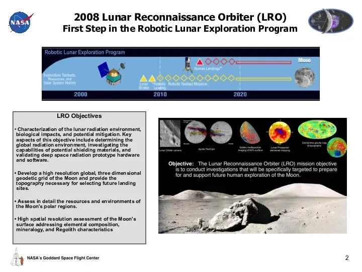
- 2. 2008 Lunar Reconnaissance Orbiter (LRO) First Step in the Robotic Lunar Exploration Program LRO Objectives Characterization
- 3. LRO provides major scientific and exploration benefit by 2009 Apollo provided only a small glimpse of
- 4. Benefit Example: Identifying Landing Sites & Resources Polar Topography/shadow mapping Resource imaging Temperature mapping (find cold
- 5. Launch in late 2008 on a Delta II rocket into a direct insertion trajectory to the
- 6. LRO Mission Overview Orbiter LRO Instruments Lunar Orbiter Laser Altimeter (LOLA) Measurement Investigation – LOLA will
- 7. Competitively Selected LRO Instruments Provide Broad Benefits
- 8. LRO Spacecraft Systems Block Diagram
- 9. LRO C&DH Architecture Block Diagram (New-8/29/05) RAD750 SBC GD-DIB # HK/IO Ka- Comm S- Comm LROC
- 10. LRO Spacecraft Systems Capabilities LRO Capability Highlights Mass: 1480 kg Power: 823 W orbit average @
- 11. Ground System Architecture Overview
- 12. LRO Mission Phases Overview
- 13. LRO Project Organization
- 14. LRO Mission Schedule Mission PDR target: November 14
- 15. LRO Project Overall Status Project almost fully staffed 45 civil servants & 23 support contractor at
- 16. LRO Element Development Status Instruments – high heritage proposed designs converging to preliminary designs Design efforts
- 17. LRO Requirements Mission SRR held 9/16-17/2005 – judged very successful Review covered development and flow down
- 18. LRO Requirements Development Roadmap LRO Level 1 Requirements ESMD-RQMT-0010 Mini-RF Allocations Electrical Spec Mechanical Spec Thermal
- 19. LRO Mission Requirements Hierarchy
- 20. LRO Overview Back-Ups
- 21. LRO Timeline to Confirmation Instrument Selection Project Funded Instrument K.O. Mtg. 1/05 2/05 3/05 4/05 5/05
- 23. Скачать презентацию
2008 Lunar Reconnaissance Orbiter (LRO)
First Step in the Robotic Lunar Exploration
2008 Lunar Reconnaissance Orbiter (LRO) First Step in the Robotic Lunar Exploration
LRO provides major scientific and exploration benefit by 2009
Apollo provided only
LRO provides major scientific and exploration benefit by 2009
Apollo provided only
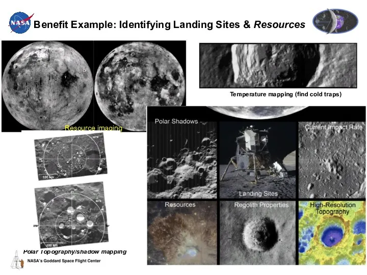
Benefit Example: Identifying Landing Sites & Resources
Polar Topography/shadow mapping
Resource imaging
Temperature mapping
Benefit Example: Identifying Landing Sites & Resources
Polar Topography/shadow mapping
Resource imaging
Temperature mapping
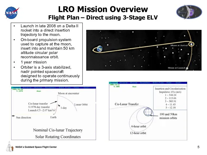
Launch in late 2008 on a Delta II rocket into a
Launch in late 2008 on a Delta II rocket into a
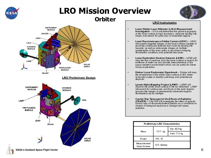
LRO Mission Overview
Orbiter
LRO Instruments
Lunar Orbiter Laser Altimeter (LOLA) Measurement Investigation
LRO Mission Overview
Orbiter
LRO Instruments
Lunar Orbiter Laser Altimeter (LOLA) Measurement Investigation
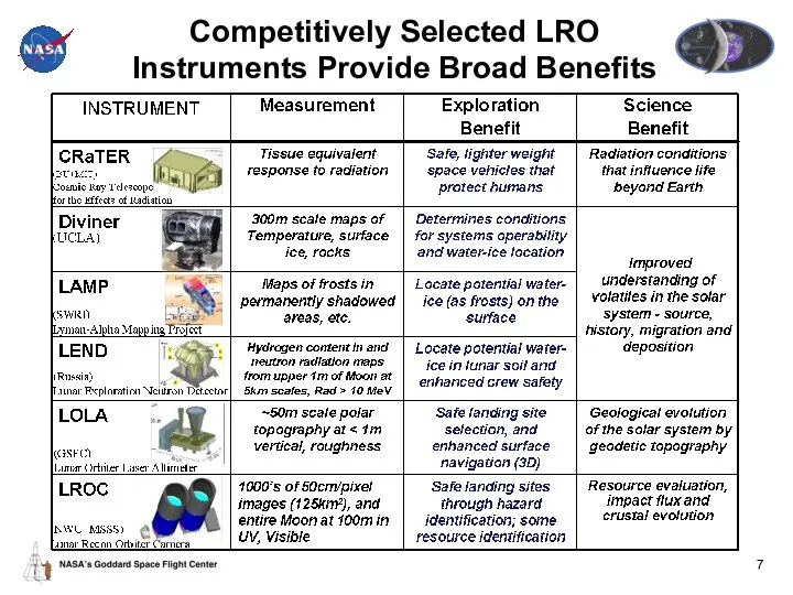
Competitively Selected LRO Instruments Provide Broad Benefits
Competitively Selected LRO Instruments Provide Broad Benefits
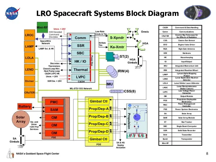
LRO Spacecraft Systems Block Diagram
LRO Spacecraft Systems Block Diagram
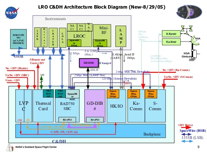
LRO C&DH Architecture Block Diagram (New-8/29/05)
RAD750
SBC
GD-DIB
#
HK/IO
Ka-
Comm
S-
Comm
LROC
L
A
M
P
L
O
L
A
NAC1
WAC
NAC2
32 Mbps
1Mbps
38.4Kbps
(UART)
Thermal
Card
1553B
Serial IF
L
E
N
D
D
i
v
i
n
e
r
C
R
A
T
E
R
SpaceWire (HSB)
1553B
LRO C&DH Architecture Block Diagram (New-8/29/05)
RAD750
SBC
GD-DIB
#
HK/IO
Ka-
Comm
S-
Comm
LROC
L
A
M
P
L
O
L
A
NAC1
WAC
NAC2
32 Mbps
1Mbps
38.4Kbps
(UART)
Thermal
Card
1553B
Serial IF
L
E
N
D
D
i
v
i
n
e
r
C
R
A
T
E
R
SpaceWire (HSB)
1553B
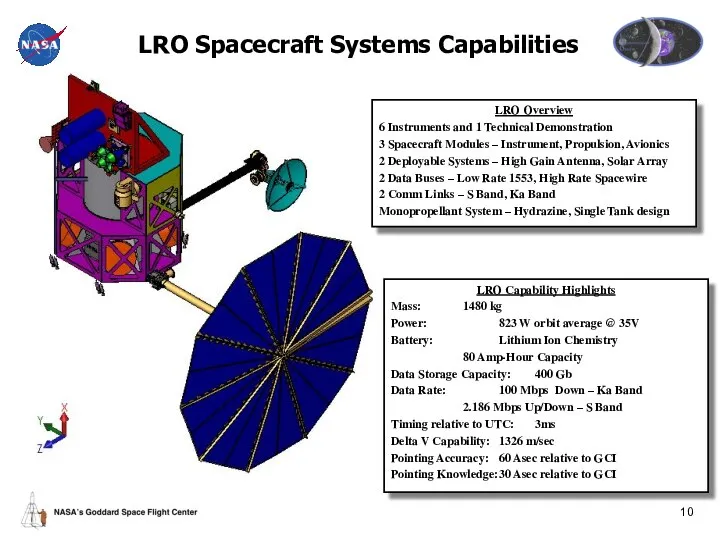
LRO Spacecraft Systems Capabilities
LRO Capability Highlights
Mass: 1480 kg
Power: 823 W orbit
LRO Spacecraft Systems Capabilities
LRO Capability Highlights
Mass: 1480 kg
Power: 823 W orbit
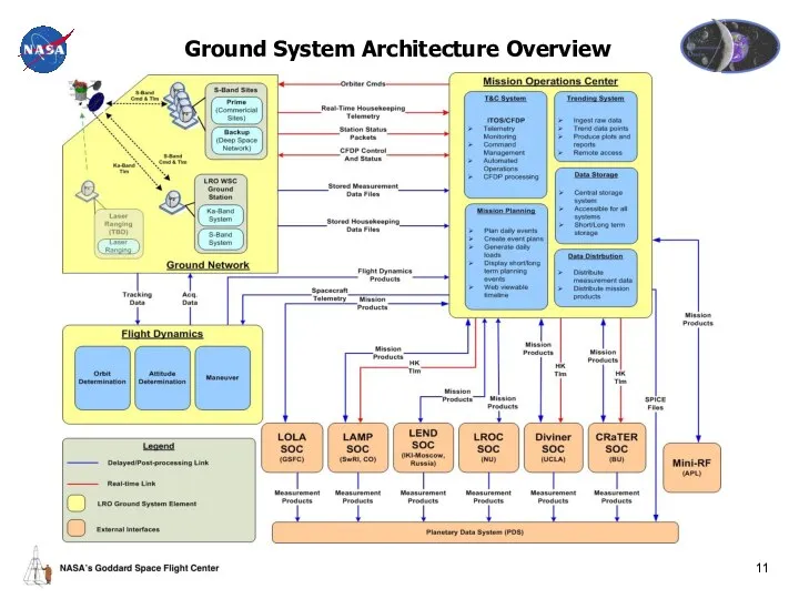
Ground System Architecture Overview
Ground System Architecture Overview
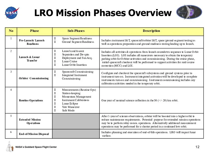
LRO Mission Phases Overview
LRO Mission Phases Overview
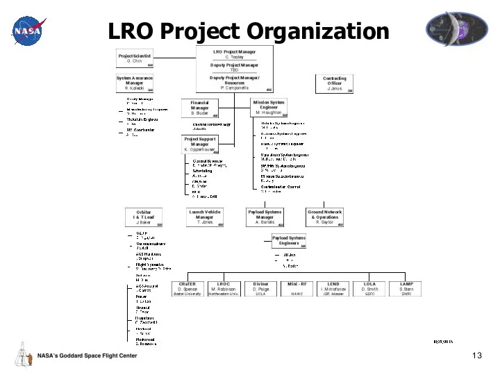
LRO Project Organization
LRO Project Organization
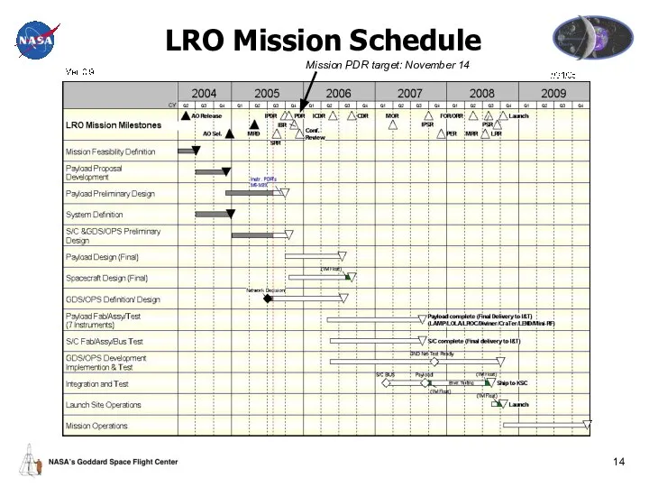
LRO Mission Schedule
Mission PDR target: November 14
LRO Mission Schedule
Mission PDR target: November 14
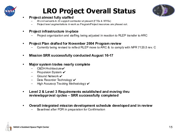
LRO Project Overall Status
Project almost fully staffed
45 civil servants & 23
LRO Project Overall Status
Project almost fully staffed
45 civil servants & 23
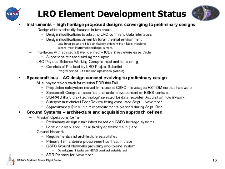
LRO Element Development Status
Instruments – high heritage proposed designs converging to
LRO Element Development Status
Instruments – high heritage proposed designs converging to
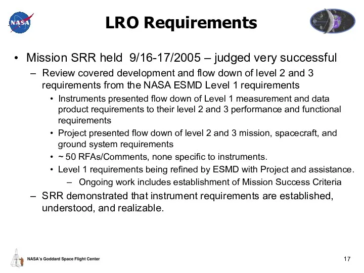
LRO Requirements
Mission SRR held 9/16-17/2005 – judged very successful
Review covered
LRO Requirements
Mission SRR held 9/16-17/2005 – judged very successful
Review covered
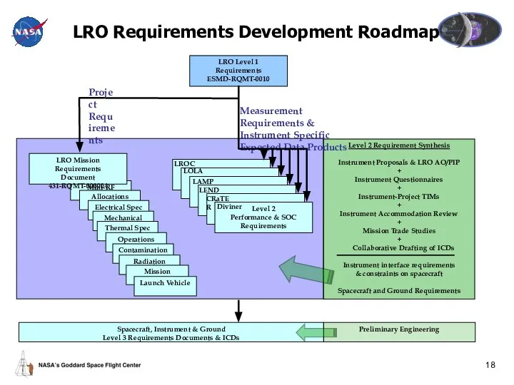
LRO Requirements Development Roadmap
LRO Level 1 Requirements
ESMD-RQMT-0010
Mini-RF
Allocations
Electrical Spec
Mechanical Spec
Thermal Spec
LRO Mission
LRO Requirements Development Roadmap
LRO Level 1 Requirements
ESMD-RQMT-0010
Mini-RF
Allocations
Electrical Spec
Mechanical Spec
Thermal Spec
LRO Mission
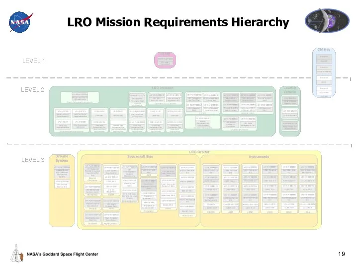
LRO Mission Requirements Hierarchy
LRO Mission Requirements Hierarchy
LRO Overview
Back-Ups
LRO Overview
Back-Ups
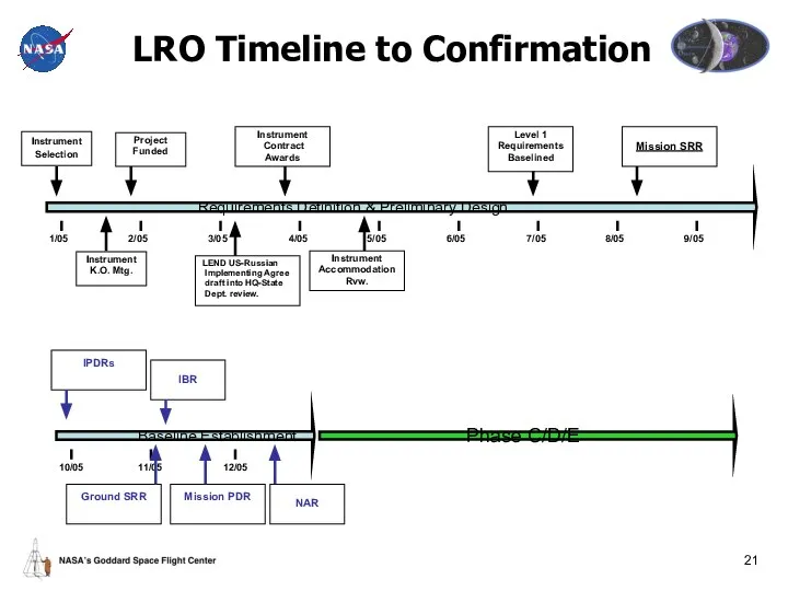
LRO Timeline to Confirmation
Instrument
Selection
Project
Funded
Instrument
K.O. Mtg.
1/05
2/05
3/05
4/05
5/05
7/05
6/05
8/05
9/05
Instrument
Accommodation
Rvw.
Instrument
Contract
Awards
Mission SRR
Requirements Definition &
LRO Timeline to Confirmation
Instrument
Selection
Project
Funded
Instrument
K.O. Mtg.
1/05
2/05
3/05
4/05
5/05
7/05
6/05
8/05
9/05
Instrument
Accommodation
Rvw.
Instrument
Contract
Awards
Mission SRR
Requirements Definition &
 Созвездия. Карта звездного неба
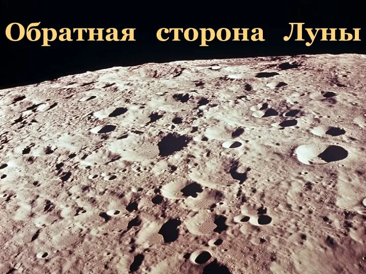 Обратная сторона Луны
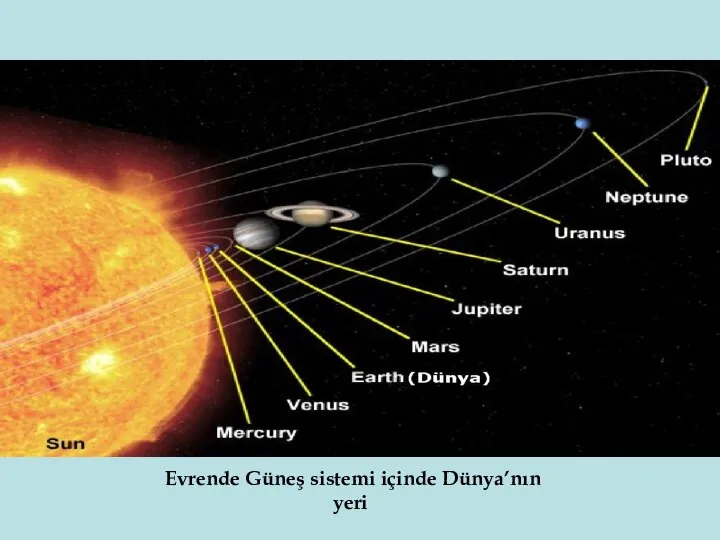 Evrende Güneş sistemi içinde Dünya’nın yeri
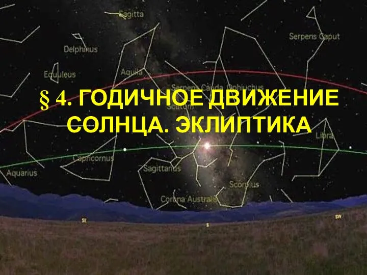 Годичное движение Солнца. Эклиптика (урок 4)
 Солнечная система. Звезды и источники их энергии. Галактика
 Путешествие в космос с Астрокотом
 Russian astronautics
 Презентация по астрономии Планета Марс
 Башкирский экономико-юридический колледж Экзопланеты
 Авиастроительный район гимназия №5 Гатауллин Р.М. 11 класс
 Зірка Сонце
 Млечный Путь и другие галактики
 Планеты Солнечной системы
 Земля Луна Выполнила Кириллова Анастасия
 10 класс ФИЗИКА И ПОЗНАНИЕ МИРА
  Большое красное пятно — загадка планеты Юпитер
 Презентация по астрономии Земля. Луна
  Движение и фазы Луны
 Астероиды. Кометы. Метеоры. Метеориты
 Девятая планета Солнечной системы
 Мирное освоение космоса
 Солнечная система. Планеты гиганты
 Утро космической эры
 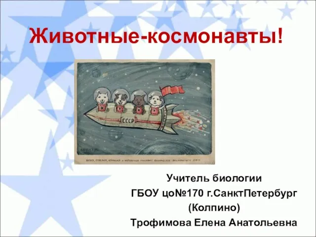 Презентация по астрономии Животные-космонавты
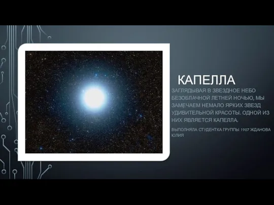 Звезда Капелла
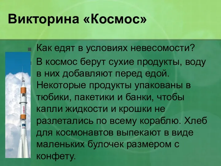 Викторина «Космос»
 Белые карлики
 Загадки Плутона