- Internal сombustion engine basics, components, systems, construction, test and perspectives

Содержание
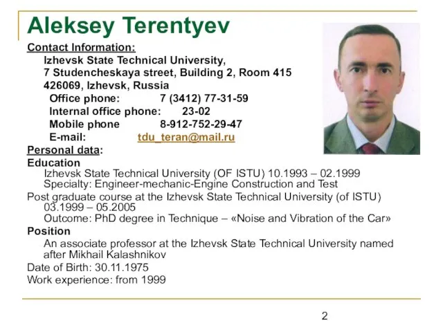
- 2. Aleksey Terentyev Contact Information: Izhevsk State Technical University, 7 Studencheskaya street, Building 2, Room 415 426069,
- 3. What is an Engine? An engine is a device which transforms one form of energy into
- 4. 1.Types of Power Plants Heat engine can be broadly classified into two categories: (a) Internal Combustion
- 5. 1.1. Classification of Heat Engines Engines whether Internal Combustion or External Combustion are of two types:
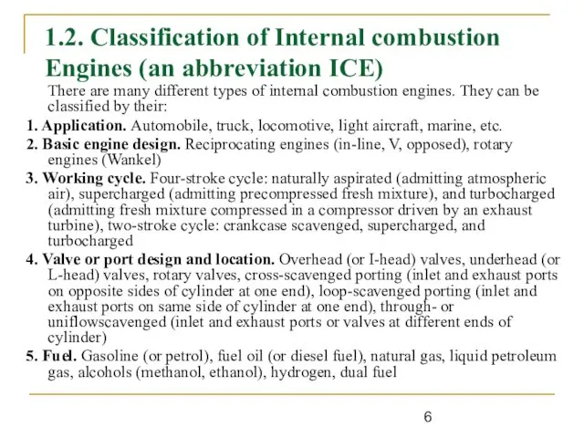
- 6. 1.2. Classification of Internal combustion Engines (an abbreviation ICE) There are many different types of internal
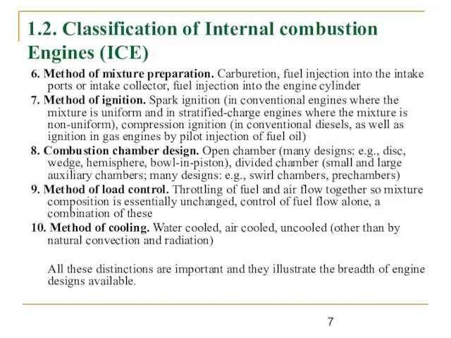
- 7. 1.2. Classification of Internal combustion Engines (ICE) 6. Method of mixture preparation. Carburetion, fuel injection into
- 8. 2. Basic Geometry of the Reciprocating Internal Combustion Engine (an abbreviation RICE) Bore - engine cylinder
- 9. 3. Main Components and Principle of Operation of the Internal Combustion Engine Figure 3.1 Cross section
- 10. 4. The Four-Stroke Petrol Engine Cycle A cycle is one complete sequence of 4 strokes of
- 11. How does this work ? The process is accompanied by any runtime heat engine are mixing
- 12. 4.1 Inlet Stroke To describe the complete cycle, let's assume that the piston is at the
- 13. 4.2 Compression Stroke On reaching the lowest position (bottom dead center) the piston begins to move
- 14. 4.3 Power stroke As the piston again reaches the top dead center the spark plugs ignite
- 15. 4.4 Exhaust stroke When the piston reaches the bottom of its stroke, the exhaust valve is
- 16. So the piston moves in the cylinder down (intake stroke), up (compression stroke), down (power stroke),
- 17. 5. Four-stroke CI Engines. Principle of operation Due to high compression ratio, the temperature at the
- 18. Four-stroke CI Engines 1.Suction stroke Only air is inducted during the suction stroke. During this stroke
- 19. 6. Two-stroke Cycle Engines – Principle of operation In two-stroke engines the cycle is completed in
- 20. Two-Stroke Cycle The air or charge is sucked through spring-loaded inlet valve when the pressure in
- 21. 7. SI Engine Components Labeled cutaway drawings of a four-stroke SI engine shown in Figure. The
- 23. Скачать презентацию
Aleksey Terentyev
Contact Information:
Izhevsk State Technical University,
7 Studencheskaya street, Building
Aleksey Terentyev
Contact Information:
Izhevsk State Technical University,
7 Studencheskaya street, Building
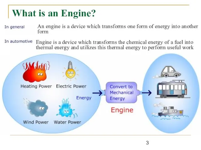
What is an Engine?
An engine is a device which transforms one
What is an Engine?
An engine is a device which transforms one
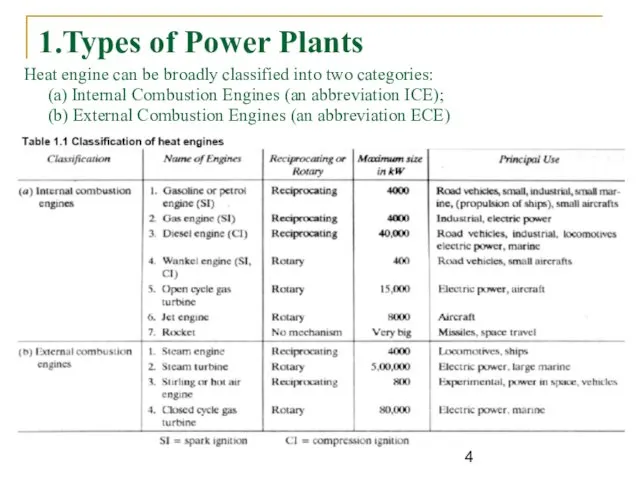
1.Types of Power Plants
Heat engine can be broadly classified into two
1.Types of Power Plants
Heat engine can be broadly classified into two
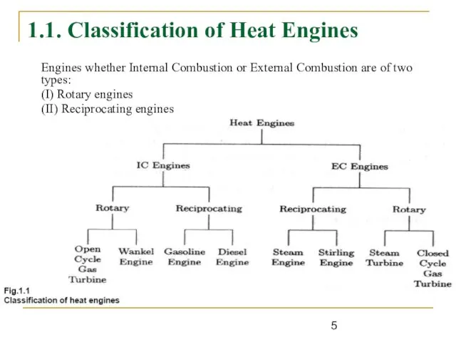
1.1. Classification of Heat Engines
Engines whether Internal Combustion or External Combustion
1.1. Classification of Heat Engines
Engines whether Internal Combustion or External Combustion
1.2. Classification of Internal combustion Engines (an abbreviation ICE)
There are many
1.2. Classification of Internal combustion Engines (an abbreviation ICE)
There are many
1.2. Classification of Internal combustion Engines (ICE)
6. Method of mixture preparation.
1.2. Classification of Internal combustion Engines (ICE)
6. Method of mixture preparation.
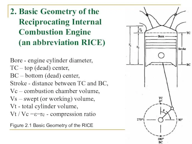
2. Basic Geometry of the Reciprocating Internal Combustion Engine (an abbreviation
2. Basic Geometry of the Reciprocating Internal Combustion Engine (an abbreviation
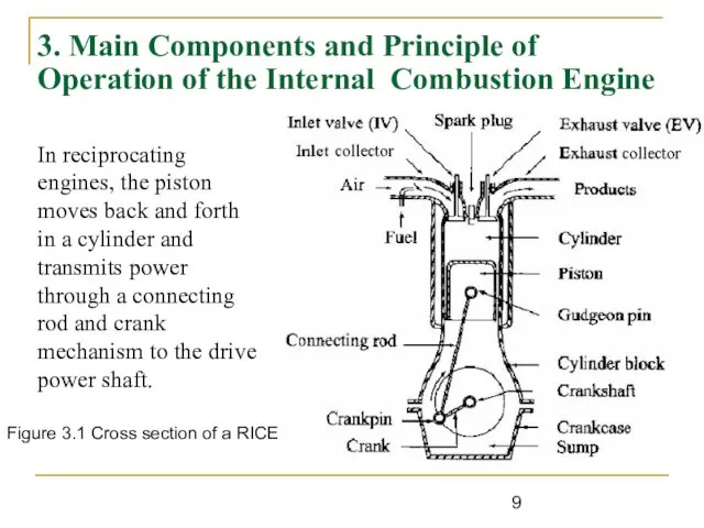
3. Main Components and Principle of Operation of the Internal Combustion
3. Main Components and Principle of Operation of the Internal Combustion
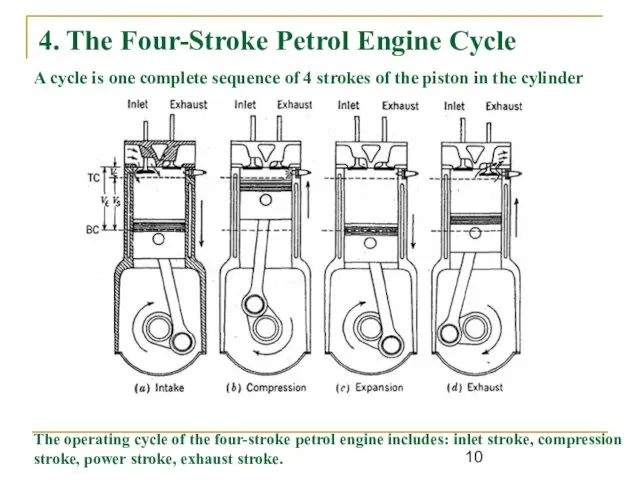
4. The Four-Stroke Petrol Engine Cycle
A cycle is one complete sequence
4. The Four-Stroke Petrol Engine Cycle
A cycle is one complete sequence
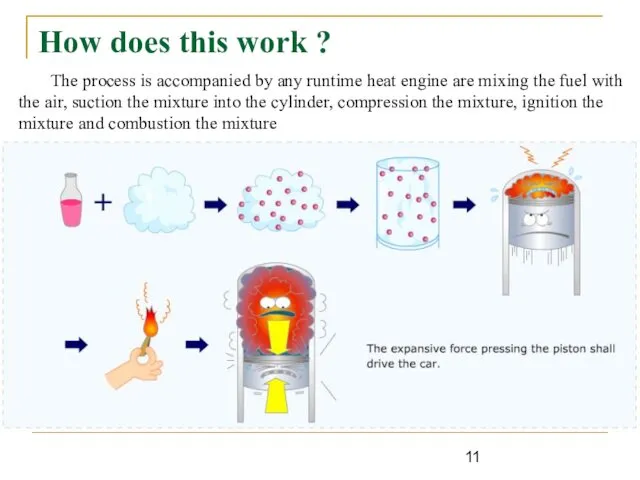
How does this work ?
The process is accompanied by any runtime
How does this work ?
The process is accompanied by any runtime
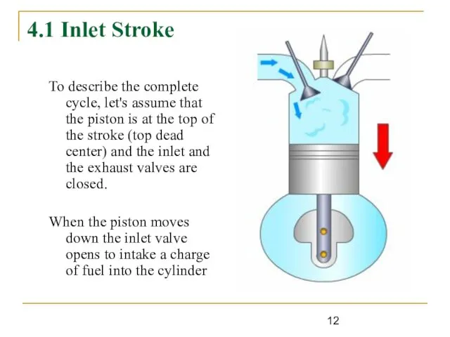
4.1 Inlet Stroke
To describe the complete cycle, let's assume that the
4.1 Inlet Stroke
To describe the complete cycle, let's assume that the

4.2 Compression Stroke
On reaching the lowest position (bottom dead center) the
4.2 Compression Stroke
On reaching the lowest position (bottom dead center) the
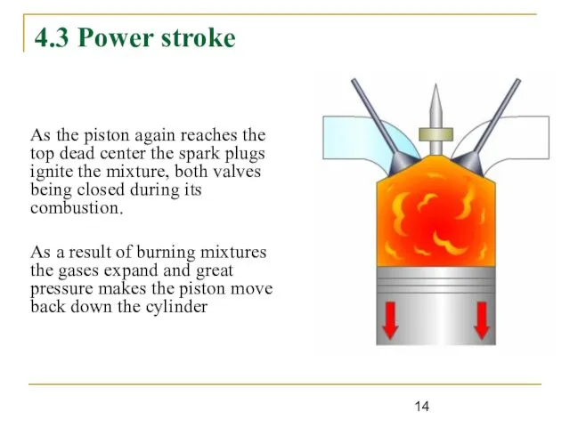
4.3 Power stroke
As the piston again reaches the top dead center
4.3 Power stroke
As the piston again reaches the top dead center
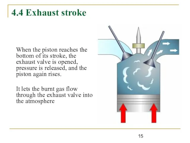
4.4 Exhaust stroke
When the piston reaches the bottom of its stroke,
4.4 Exhaust stroke
When the piston reaches the bottom of its stroke,
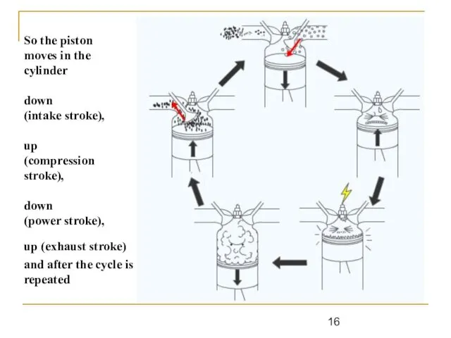
So the piston
moves in the cylinder
down
(intake stroke),
up
So the piston moves in the cylinder down (intake stroke), up
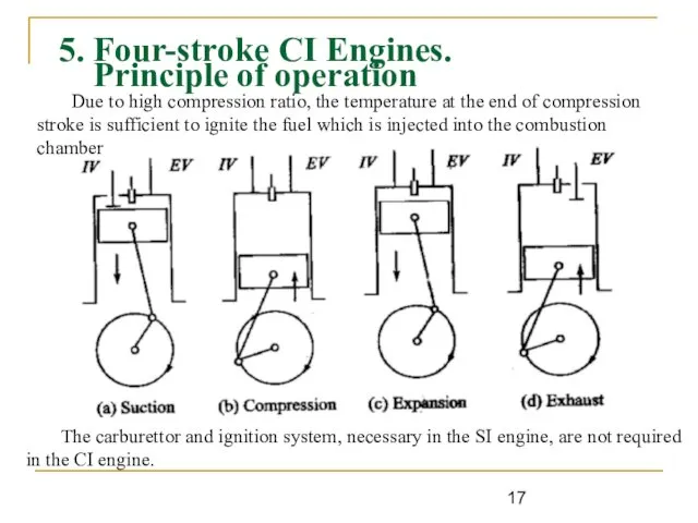
5. Four-stroke CI Engines.
Principle of operation
Due to high compression ratio,
5. Four-stroke CI Engines.
Principle of operation
Due to high compression ratio,
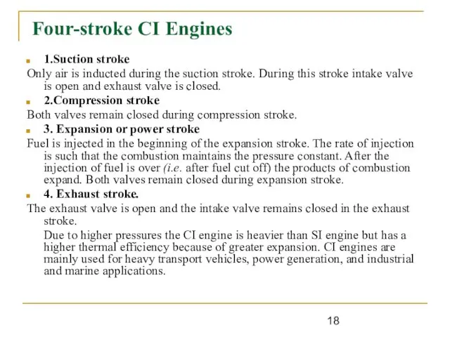
Four-stroke CI Engines
1.Suction stroke
Only air is inducted during the suction
Four-stroke CI Engines
1.Suction stroke
Only air is inducted during the suction
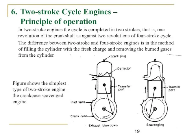
6. Two-stroke Cycle Engines –
Principle of operation
In two-stroke engines the
6. Two-stroke Cycle Engines –
Principle of operation
In two-stroke engines the
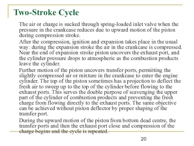
Two-Stroke Cycle
The air or charge is sucked through spring-loaded inlet
Two-Stroke Cycle
The air or charge is sucked through spring-loaded inlet
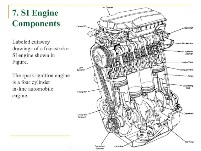
7. SI Engine
Components
Labeled cutaway drawings of a four-stroke SI engine
7. SI Engine
Components
Labeled cutaway drawings of a four-stroke SI engine
 Тиристор деп төрт деңгейлі жартылай өткізгіш құрылғылардын
 Презентация по физике "Как управлять равновесием" - скачать
  Электрическая дуга
 Сила упругости
 Явление радиоактивности Открытие радиоактивности Виды радиоактивных излучений Радиоактивные превращения «Радиоактивные» учё
 Электростатика. (Лекция 11)
 Презентация Поверхностное натяжение жидкости. Смачивание. Капиллярность
  Детали машин и основы конструирования
 Презентация Плотность вещества Взаимодействие тел
 Механічна енергія
 Аттестационная работа. Проектно-исследовательская деятельность в рамках науки «Физика». (7 класс)
 Электростатика. Поле в диэлектриках
 Импульс тела. Закон сохранения импульса
 ПОЛУЧЕНИЕ РАДИОАКТИВНЫХ ИЗОТОПОВ И ИХ ПРИМЕНЕНИЕ
 Экспериментальные исследования нагрева и зажигания растительных горючих материалов
 Модель атома Резерфорда. Атомные спектры. Постулаты Бора. Опыт Франка и Герца. Элементарная боровская теория водородного атома
 Урок – обобщение по теме Основы МКТ
 Электростатическое поле в вакууме
 Силы инерции. Уравнение Ньютона для неинерциальных систем отсчета
 Э.М. Спиридонов. Эволюция минералов вольфрама в зоне гипергенеза
 Классификация фотоаппаратов по размеру светочувствительного элемента
 Физические величины. Измерение физических величин. Точность и погрешность измерения
 Презентация по физике "Альберт Эйнштейн" - скачать
  Квантовые свойства излучений (Лекция 4)
 Механическое движение
 Интернет-ресурсы, посвящённые физике
 Лучевая обработка материалов
 Нахождение теплоемкости металлов в опытах по теплообмену с водой