- Bottom mounted freezer type

Содержание
- 2. Contents 1. PRECAUTIONS (SAFETY WARNINGS).............3 2. PRODUCT SPECIFICATIONS ...................7 3. DISASSEMBLY & REASSEMBLY.................14 4. TROUBLE SHOOTING........................
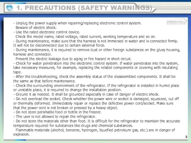
- 3. 1. PRECAUTIONS (SAFETY WARNINGS) - Unplug the power supply when repairing/replacing electronic control system. Beware of
- 4. Read all instructions before repairing the product and keep to the instructions in order to prevent
- 5. 1. PRECAUTIONS (SAFETY WARNINGS)
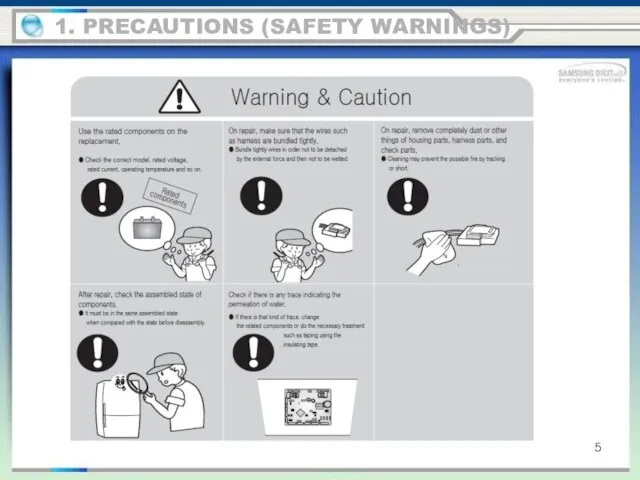
- 6. Please ler users know following warnings & cautions in detail. 1. PRECAUTIONS (SAFETY WARNINGS)
- 7. product feature 2. PRODUCT SPECIFICATIONS NO FROST INVERTER COMP INTERNAL LED DISPLAY MULTI FLOW
- 8. DISPLAY SHELF REF Dairy Bin Door Bin TRAY VEG TRAY FRE LED LAMP RECESSED HANDLE product
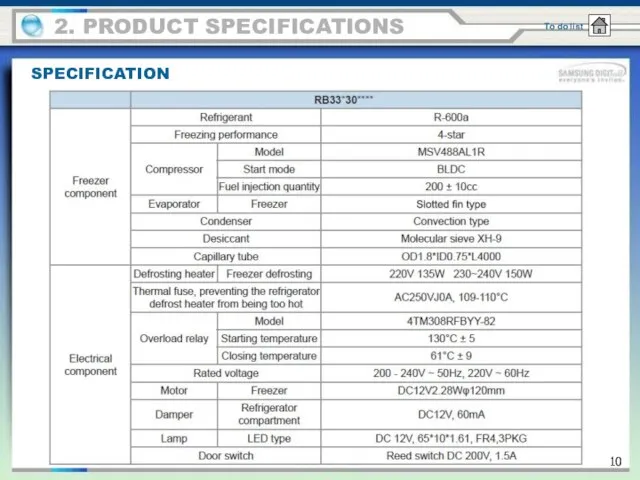
- 9. 2. PRODUCT SPECIFICATIONS SPECIFICATION
- 10. 2. PRODUCT SPECIFICATIONS SPECIFICATION
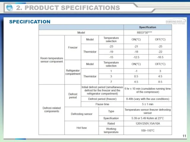
- 11. 2. PRODUCT SPECIFICATIONS SPECIFICATION
- 12. DIMENSION 2. PRODUCT SPECIFICATIONS
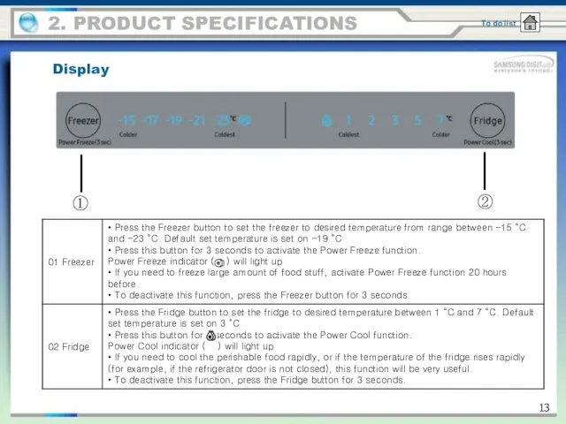
- 13. 2. PRODUCT SPECIFICATIONS Display ① ②
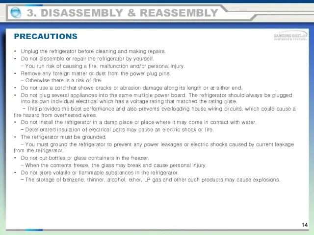
- 14. PRECAUTIONS 3. DISASSEMBLY & REASSEMBLY Unplug the refrigerator before cleaning and making repairs. Do not dissemble
- 15. 3. DISASSEMBLY & REASSEMBLY TOOL NEEDED
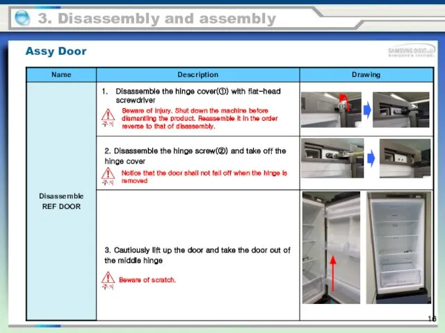
- 16. 3. Disassembly and assembly Beware of injury. Shut down the machine before dismantling the product. Reassemble
- 17. Notice that the door shall not fall off when the hinge is removed Beware of scratch.
- 18. Refrigerator compartment 3. Disassembly and assembly
- 19. Refrigerator compartment 3. Disassembly and assembly
- 20. Refrigerator compartment 3. Disassembly and assembly
- 21. Refrigerator compartment 3. Disassembly and assembly
- 22. Refrigerator compartment 3. Disassembly and assembly
- 23. Refrigerator compartment 3. Disassembly and assembly
- 24. Refrigerator compartment 3. Disassembly and assembly
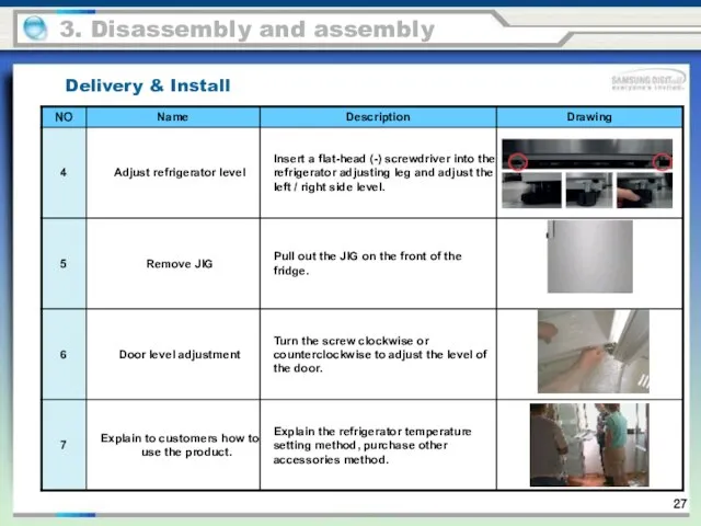
- 25. Delivery & Install Be careful not to scratch the door. Move the fridge in pairs. 3.
- 26. Delivery & Install 3. Disassembly and assembly
- 27. Delivery & Install 3. Disassembly and assembly
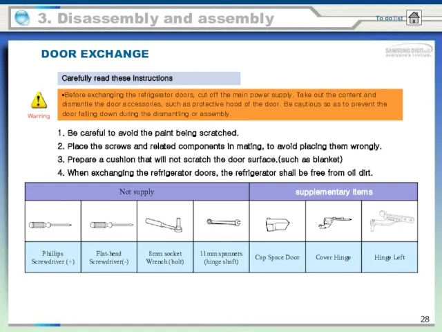
- 28. DOOR EXCHANGE Warning Carefully read these instructions 3. Disassembly and assembly •Before exchanging the refrigerator doors,
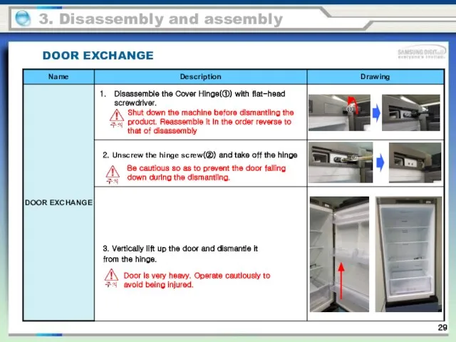
- 29. 3. Disassembly and assembly Shut down the machine before dismantling the product. Reassemble it in the
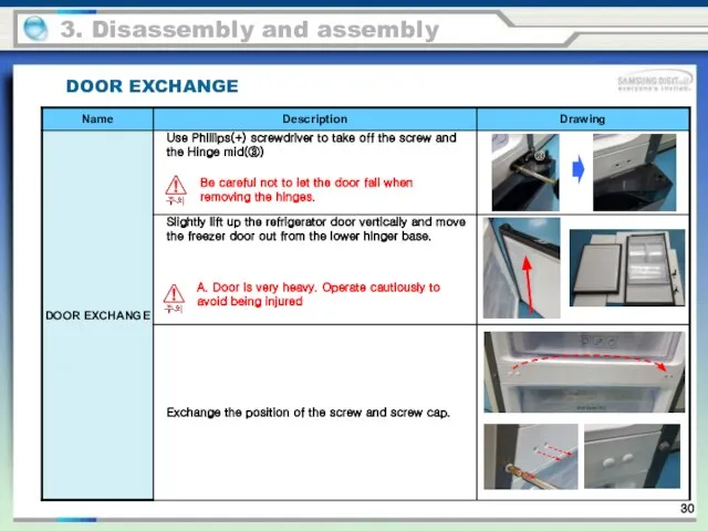
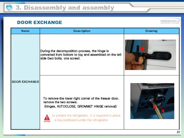
- 30. Be careful not to let the door fall when removing the hinges. A. Door is very
- 31. to protect the refrigerator, it is required to place a big cardboard under the refrigerator. 3.
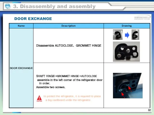
- 32. 3. Disassembly and assembly DOOR EXCHANGE to protect the refrigerator, it is required to place a
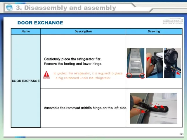
- 33. 3. Disassembly and assembly DOOR EXCHANGE to protect the refrigerator, it is required to place a
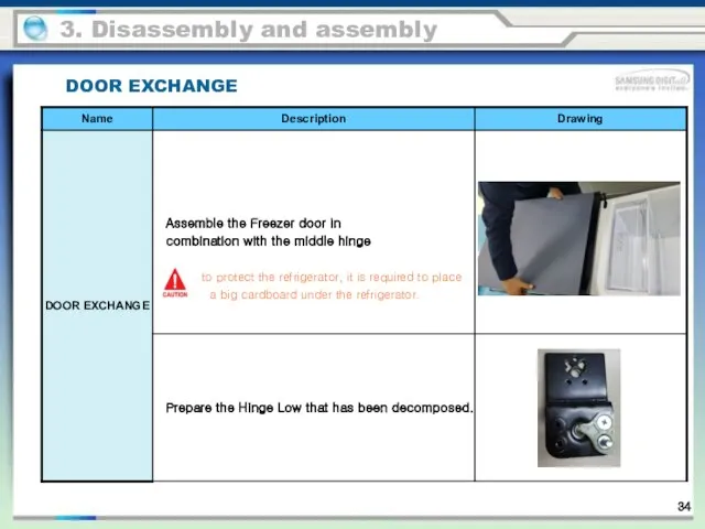
- 34. 3. Disassembly and assembly DOOR EXCHANGE to protect the refrigerator, it is required to place a
- 35. 3. Disassembly and assembly DOOR EXCHANGE
- 36. 3. Disassembly and assembly DOOR EXCHANGE
- 37. 3. Disassembly and assembly DOOR EXCHANGE
- 38. 3. Disassembly and assembly DOOR EXCHANGE
- 39. Replace the custom panel To prevent any damage, add the cushion on the floor. 3. Disassembly
- 40. Replace the custom panel 3. Disassembly and assembly
- 41. To prevent any damage, add the cushion on the floor. Replace the custom panel 3. Disassembly
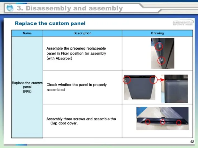
- 42. Replace the custom panel 3. Disassembly and assembly
- 43. 1. Press the “freezer” button on PCB control panel and “refrigerator compartment” button for more than
- 44. 2) Test mode description 1) Forced Operation Function 1-3) When the Forced Operation is selected, the
- 45. 2) Forced Defrost Function 2-1) When it is on the Forced Operation during the Test Mode,
- 46. 1-1) When the unit is plugged into the power, MICOM diagnoses the status of the temperature
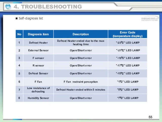
- 47. 55 4. TROUBLESHOOTING ※ Self-diagnosis list
- 48. 56 4. TROUBLESHOOTING ※ Self-diagnosis list
- 49. 57 4. TROUBLESHOOTING ※ Self-diagnosis list
- 50. 58 4. TROUBLESHOOTING ※ Self-diagnosis list
- 51. 59 4. TROUBLESHOOTING ※ Self-diagnosis list
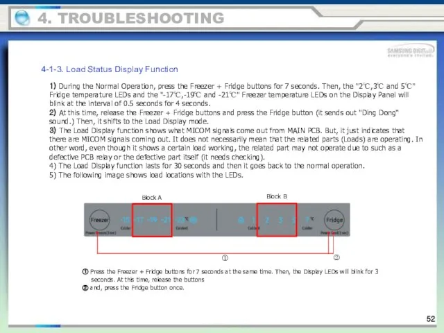
- 52. 4. TROUBLESHOOTING 4-1-3. Load Status Display Function 1) During the Normal Operation, press the Freezer +
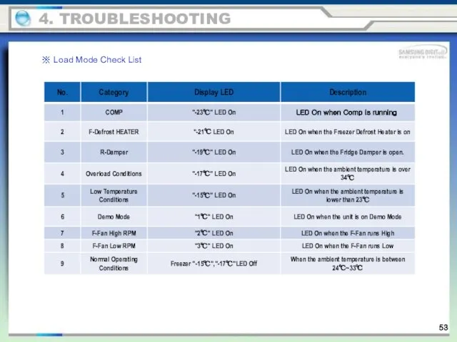
- 53. 4. TROUBLESHOOTING ※ Load Mode Check List
- 54. 4-1-4. Restoration of Previous Settings upon Instant Power Outage 1) If the Display Panel is initialized
- 55. 4-1-5. Demo Mode Function for Store Display 1) During the Normal Operation, press the Freezer +
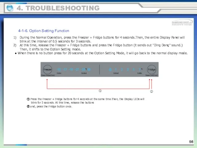
- 56. 4-1-6. Option Setting Function During the Normal Operation, press the Freezer + Fridge buttons for 4
- 57. 4-1-7. Option Mode & Button Operation Description F-ROOM STEP R-ROOM STEP ① ② ③ ④ 4.
- 58. ● The Bar Type Display Panel shows the numbers as shown in the following tables (Binary
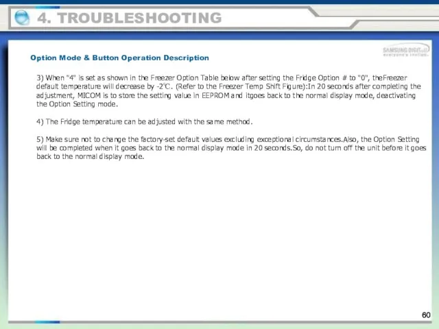
- 59. ● When the Display Panel converts to the Option Setting mode, the entire Display except the
- 60. 3) When "4" is set as shown in the Freezer Option Table below after setting the
- 61. 4-1-8. Option TABLE 1) Freezer Temp Shift Table For example, the default temp of freezer is
- 62. 2) Fridge Temp Shift Table For example, the default temp of fridge is +2.0ºC -15℃ -17℃
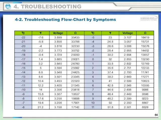
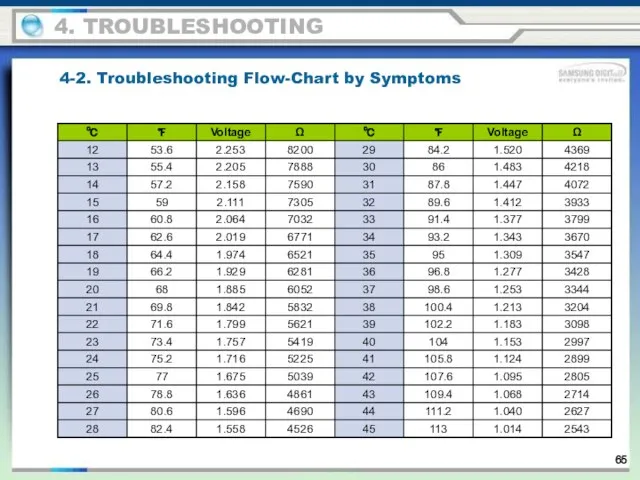
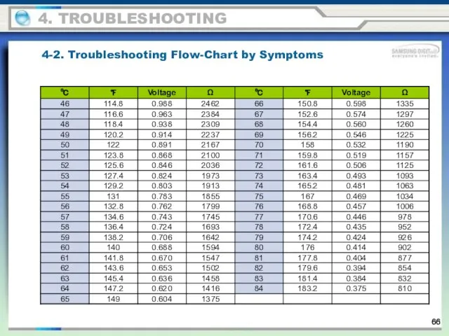
- 63. DATA1.Temp Table Conversion Table - Temperature/MICOM PORT Voltage/Resistance SENSOR CHIP : PX41C 4. TROUBLESHOOTING 4-2. Troubleshooting
- 64. 4. TROUBLESHOOTING 4-2. Troubleshooting Flow-Chart by Symptoms
- 65. 4. TROUBLESHOOTING 4-2. Troubleshooting Flow-Chart by Symptoms
- 66. 4. TROUBLESHOOTING 4-2. Troubleshooting Flow-Chart by Symptoms
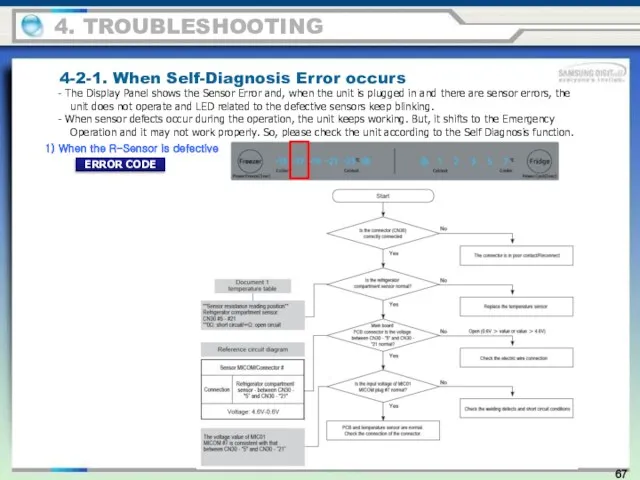
- 67. 4-2-1. When Self-Diagnosis Error occurs - The Display Panel shows the Sensor Error and, when the
- 68. 2) When the EXT Sensor is defective 4-2-1. When Self-Diagnosis Error occurs 4. TROUBLESHOOTING ERROR CODE
- 69. 3) When the F-Sensor is defective 4-2-1. When Self-Diagnosis Error occurs 4. TROUBLESHOOTING ERROR CODE
- 70. 4) When the DEF-Sensor is defective 4-2-1. When Self-Diagnosis Error occurs 4. TROUBLESHOOTING ERROR CODE
- 71. 4-2-2. When the Freezer Fan does not operate (BLDC Motor) 1) F FAN ERROR 4. TROUBLESHOOTING
- 72. 4. TROUBLESHOOTING 4-2-3. When Defrost does not work (F DEF Heater) ERROR CODE
- 73. 4. TROUBLESHOOTING 4-2-3. When Defrost does not work (F DEF Heater) ERROR CODE
- 74. 4-2-4. When there is No Power (MAIN PBA) 4. TROUBLESHOOTING
- 75. 4-2-4. When there is No Power (MAIN PBA) 4. TROUBLESHOOTING
- 76. ① When there is "Ding Dong" sound not stopping 4-2-5 When the unit keeps alarming (Buzzer
- 77. ② When it keeps 'Beeping 4-2-5 When the unit keeps alarming (Buzzer Sound) 4. TROUBLESHOOTING
- 78. ③ No Buzzer Sound 4-2-5 When the unit keeps alarming (Buzzer Sound) 4. TROUBLESHOOTING This model
- 79. 4-2-6. When PANEL PCB operates abnormally ① When PANEL PCB does not light up or partially
- 80. 4-2-6. When PANEL PCB operates abnormally 4. TROUBLESHOOTING
- 81. 4-2-7. When the Room Lamp (LED) does not light up 4. TROUBLESHOOTING
- 82. 4-2-8. When Fridge Damper does not work 4. TROUBLESHOOTING
- 83. If Failure Condition is detected during compressor is operating, immediately stop Compressor operating and stand by
- 84. 5-1. PART Layout (Main Board) 5. PCB/PBA DIAGRAM 1. Inverter COMP. Signal Section 2.EEPROM:Storing/Writing various data
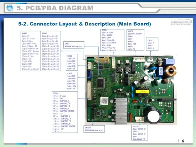
- 85. 119 5-2. Connector Layout & Description (Main Board) 5. PCB/PBA DIAGRAM
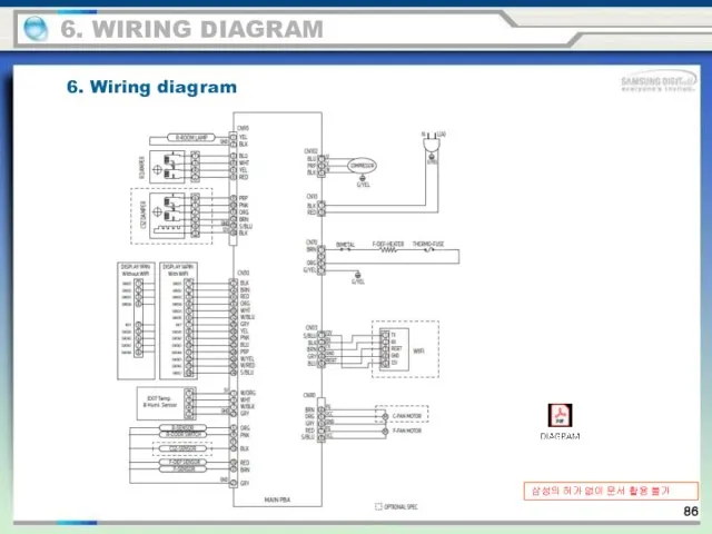
- 86. 6. WIRING DIAGRAM 6. Wiring diagram 삼성의 허가 없이 문서 활용 불가
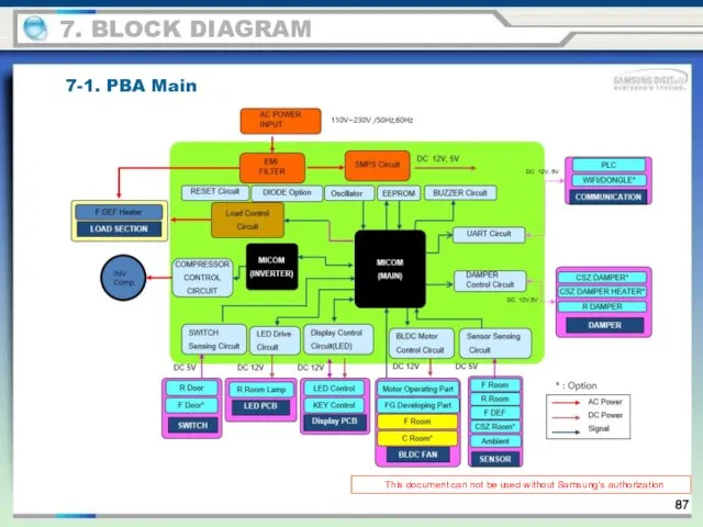
- 87. This document can not be used without Samsung's authorization 7. BLOCK DIAGRAM 7-1. PBA Main
- 88. Condenser (Option) 8. CYCLE 87
- 89. 9. Sensor layout Fridge Temp Sensor (REF COVER DUCT) Freezer Temp Sensor (FRE COVER DUCT) Humidity
- 90. 10-1. Nomenclature 10. REFERENCE INFORMATION 89
- 92. Скачать презентацию
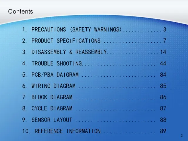
Contents
1. PRECAUTIONS (SAFETY WARNINGS).............3
2. PRODUCT SPECIFICATIONS ...................7
3. DISASSEMBLY & REASSEMBLY.................14
4.
Contents
1. PRECAUTIONS (SAFETY WARNINGS).............3
2. PRODUCT SPECIFICATIONS ...................7
3. DISASSEMBLY & REASSEMBLY.................14
4.
1. PRECAUTIONS (SAFETY WARNINGS)
- Unplug the power supply when repairing/replacing electronic
1. PRECAUTIONS (SAFETY WARNINGS)
- Unplug the power supply when repairing/replacing electronic
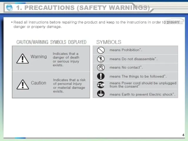
Read all instructions before repairing the product and keep to the
Read all instructions before repairing the product and keep to the
1. PRECAUTIONS (SAFETY WARNINGS)
1. PRECAUTIONS (SAFETY WARNINGS)
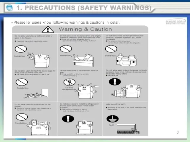
Please ler users know following warnings & cautions in detail.
1. PRECAUTIONS
Please ler users know following warnings & cautions in detail.
1. PRECAUTIONS
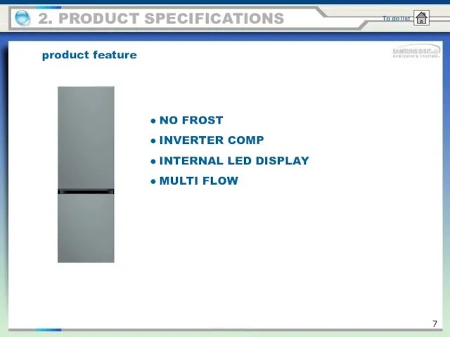
product feature
2. PRODUCT SPECIFICATIONS
NO FROST
INVERTER COMP
INTERNAL LED DISPLAY
MULTI FLOW
product feature
2. PRODUCT SPECIFICATIONS
NO FROST
INVERTER COMP
INTERNAL LED DISPLAY
MULTI FLOW
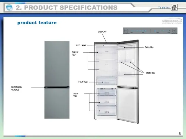
DISPLAY
SHELF REF
Dairy Bin
Door Bin
TRAY VEG
TRAY FRE
LED LAMP
RECESSED HANDLE
product feature
2. PRODUCT SPECIFICATIONS
DISPLAY
SHELF REF
Dairy Bin
Door Bin
TRAY VEG
TRAY FRE
LED LAMP
RECESSED HANDLE
product feature
2. PRODUCT SPECIFICATIONS
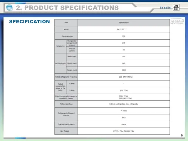
2. PRODUCT SPECIFICATIONS
SPECIFICATION
2. PRODUCT SPECIFICATIONS
SPECIFICATION
2. PRODUCT SPECIFICATIONS
SPECIFICATION
2. PRODUCT SPECIFICATIONS
SPECIFICATION
2. PRODUCT SPECIFICATIONS
SPECIFICATION
2. PRODUCT SPECIFICATIONS
SPECIFICATION
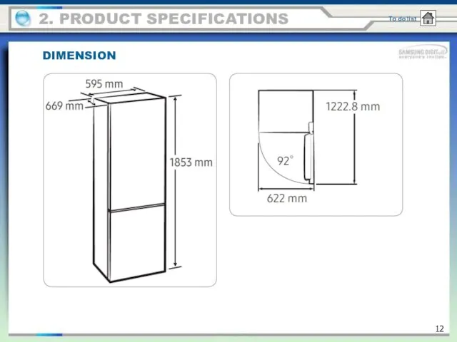
DIMENSION
2. PRODUCT SPECIFICATIONS
DIMENSION
2. PRODUCT SPECIFICATIONS
2. PRODUCT SPECIFICATIONS
Display
①
②
2. PRODUCT SPECIFICATIONS
Display
①
②
PRECAUTIONS
3. DISASSEMBLY & REASSEMBLY
Unplug the refrigerator before cleaning and making repairs.
Do
PRECAUTIONS
3. DISASSEMBLY & REASSEMBLY
Unplug the refrigerator before cleaning and making repairs.
Do
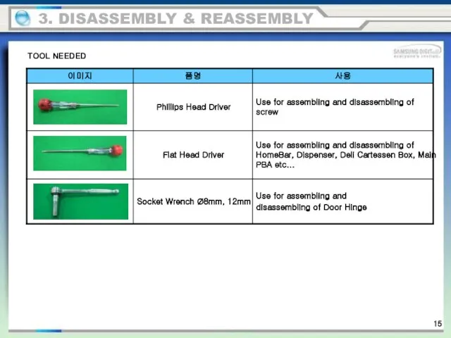
3. DISASSEMBLY & REASSEMBLY
TOOL NEEDED
3. DISASSEMBLY & REASSEMBLY
TOOL NEEDED
3. Disassembly and assembly
Beware of injury. Shut down the machine before
3. Disassembly and assembly
Beware of injury. Shut down the machine before
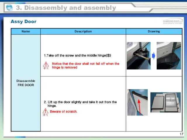
Notice that the door shall not fall off when the hinge
Notice that the door shall not fall off when the hinge
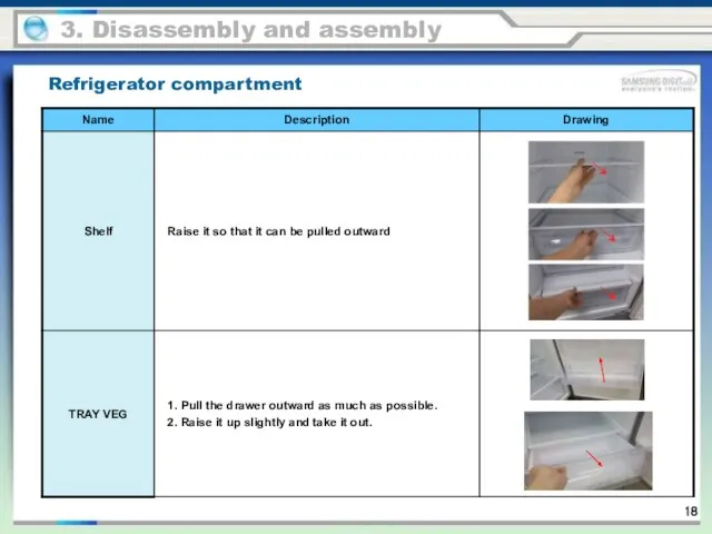
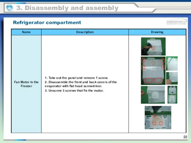
Refrigerator compartment
3. Disassembly and assembly
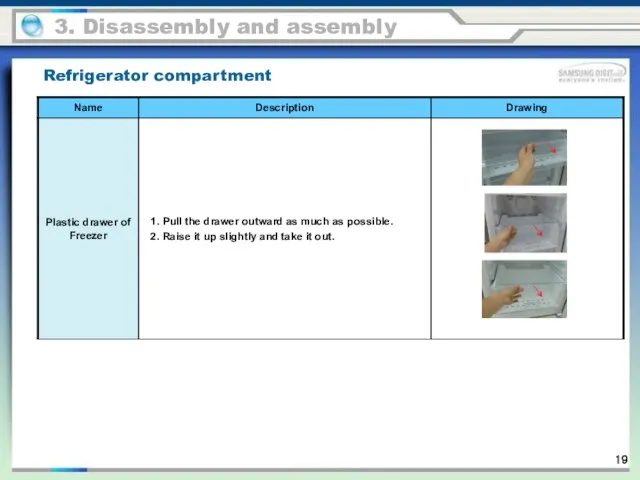
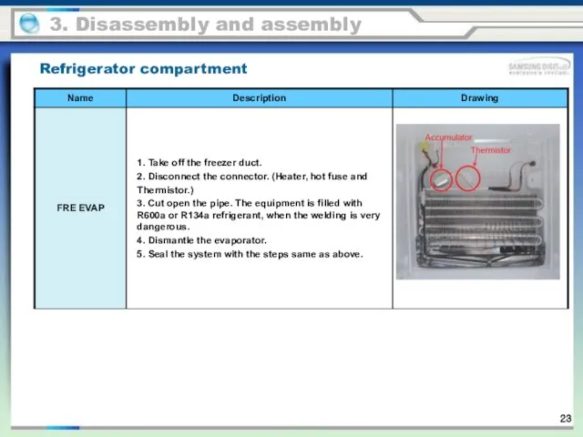
Refrigerator compartment
3. Disassembly and assembly
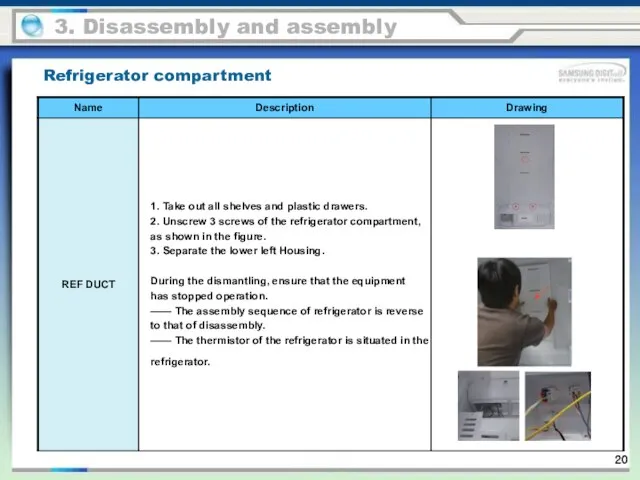
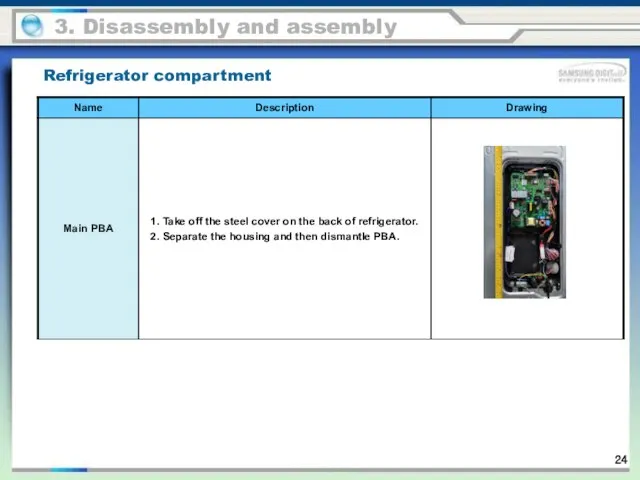
Refrigerator compartment
3. Disassembly and assembly
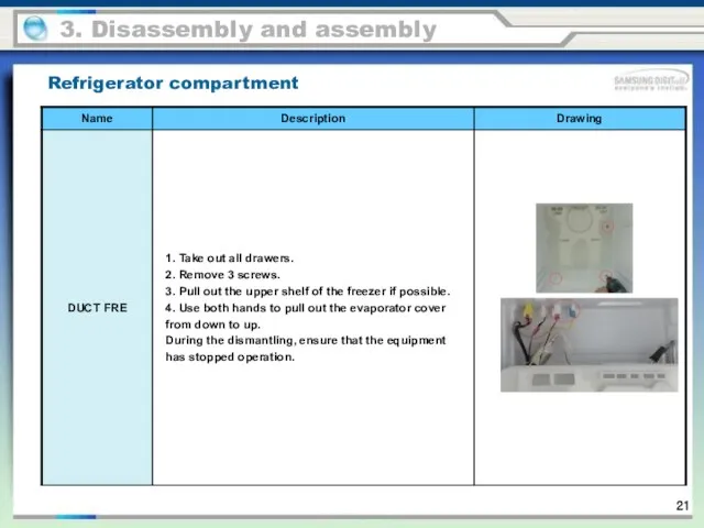
Refrigerator compartment
3. Disassembly and assembly
Refrigerator compartment
3. Disassembly and assembly
Refrigerator compartment
3. Disassembly and assembly
Refrigerator compartment
3. Disassembly and assembly
Refrigerator compartment
3. Disassembly and assembly
Refrigerator compartment
3. Disassembly and assembly
Refrigerator compartment
3. Disassembly and assembly
Refrigerator compartment
3. Disassembly and assembly
Refrigerator compartment
3. Disassembly and assembly
Refrigerator compartment
3. Disassembly and assembly
Refrigerator compartment
3. Disassembly and assembly

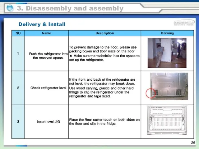
Delivery & Install
Be careful not to scratch the door.
Move the fridge
Delivery & Install
Be careful not to scratch the door.
Move the fridge
Delivery & Install
3. Disassembly and assembly
Delivery & Install
3. Disassembly and assembly
Delivery & Install
3. Disassembly and assembly
Delivery & Install
3. Disassembly and assembly
DOOR EXCHANGE
Warning
Carefully read these instructions
3. Disassembly and assembly
•Before exchanging the refrigerator
DOOR EXCHANGE
Warning
Carefully read these instructions
3. Disassembly and assembly
•Before exchanging the refrigerator
3. Disassembly and assembly
Shut down the machine before dismantling the product.
3. Disassembly and assembly
Shut down the machine before dismantling the product.
Be careful not to let the door fall when removing the
Be careful not to let the door fall when removing the
to protect the refrigerator, it is required to place a big
to protect the refrigerator, it is required to place a big
3. Disassembly and assembly
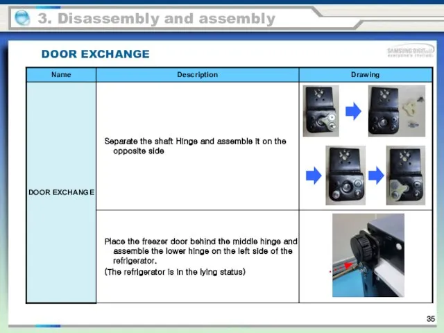
DOOR EXCHANGE
to protect the refrigerator, it is required
3. Disassembly and assembly
DOOR EXCHANGE
to protect the refrigerator, it is required
3. Disassembly and assembly
DOOR EXCHANGE
to protect the refrigerator, it is required
3. Disassembly and assembly
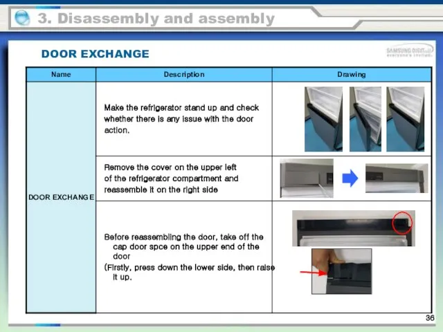
DOOR EXCHANGE
to protect the refrigerator, it is required
3. Disassembly and assembly
DOOR EXCHANGE
to protect the refrigerator, it is required
3. Disassembly and assembly
DOOR EXCHANGE
to protect the refrigerator, it is required
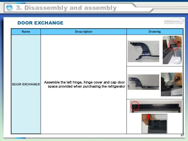
3. Disassembly and assembly
DOOR EXCHANGE
3. Disassembly and assembly
DOOR EXCHANGE
3. Disassembly and assembly
DOOR EXCHANGE
3. Disassembly and assembly
DOOR EXCHANGE
3. Disassembly and assembly
DOOR EXCHANGE
3. Disassembly and assembly
DOOR EXCHANGE
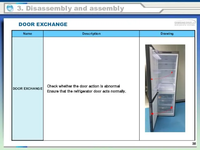
3. Disassembly and assembly
DOOR EXCHANGE
3. Disassembly and assembly
DOOR EXCHANGE
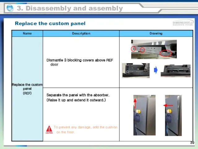
Replace the custom panel
To prevent any damage, add the cushion on
Replace the custom panel
To prevent any damage, add the cushion on

Replace the custom panel
3. Disassembly and assembly
Replace the custom panel
3. Disassembly and assembly
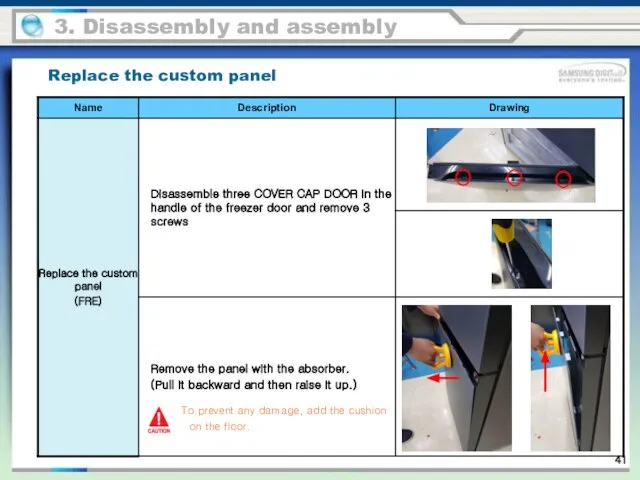
To prevent any damage, add the cushion on the floor.
Replace the
To prevent any damage, add the cushion on the floor.
Replace the
Replace the custom panel
3. Disassembly and assembly
Replace the custom panel
3. Disassembly and assembly
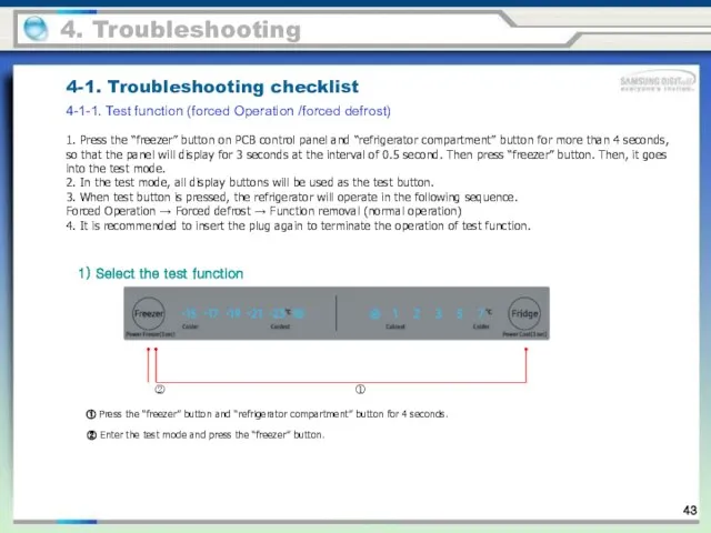
1. Press the “freezer” button on PCB control panel and “refrigerator
1. Press the “freezer” button on PCB control panel and “refrigerator
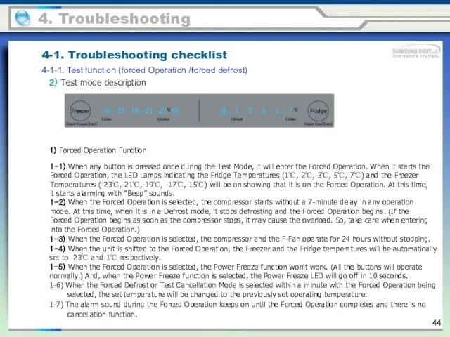
2) Test mode description
1) Forced Operation Function
1-3) When the Forced Operation
2) Test mode description
1) Forced Operation Function
1-3) When the Forced Operation
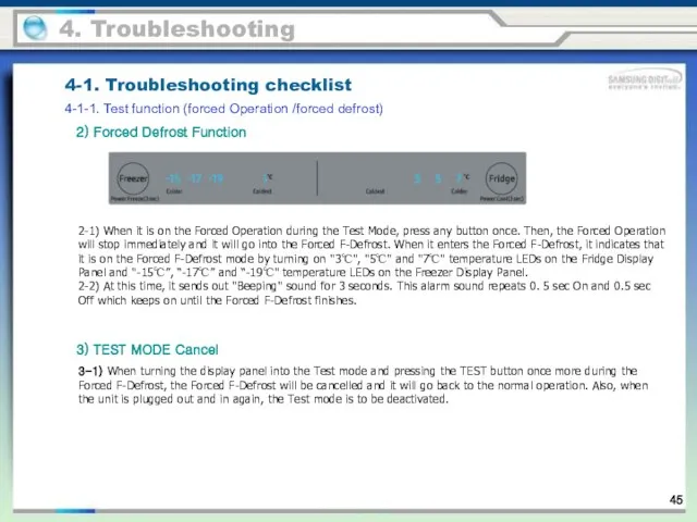
2) Forced Defrost Function
2-1) When it is on the Forced Operation
2) Forced Defrost Function
2-1) When it is on the Forced Operation
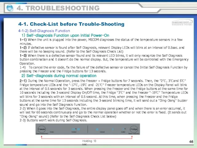
1-1) When the unit is plugged into the power, MICOM diagnoses
1-1) When the unit is plugged into the power, MICOM diagnoses
55
4. TROUBLESHOOTING
※ Self-diagnosis list
55
4. TROUBLESHOOTING
※ Self-diagnosis list
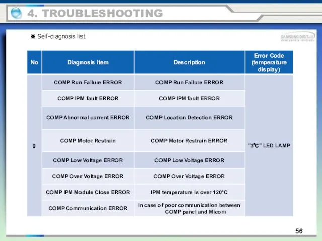
56
4. TROUBLESHOOTING
※ Self-diagnosis list
56
4. TROUBLESHOOTING
※ Self-diagnosis list
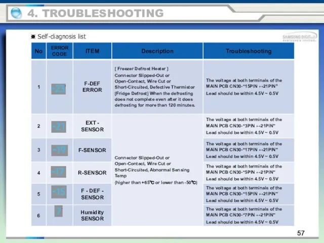
57
4. TROUBLESHOOTING
※ Self-diagnosis list
57
4. TROUBLESHOOTING
※ Self-diagnosis list
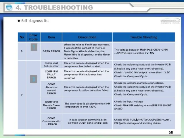
58
4. TROUBLESHOOTING
※ Self-diagnosis list
58
4. TROUBLESHOOTING
※ Self-diagnosis list
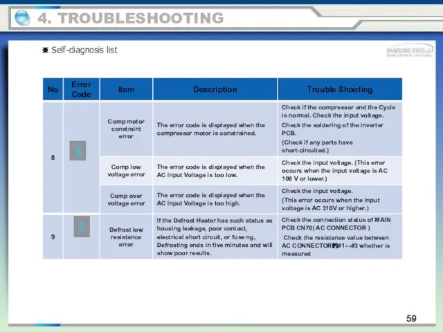
59
4. TROUBLESHOOTING
※ Self-diagnosis list
59
4. TROUBLESHOOTING
※ Self-diagnosis list
4. TROUBLESHOOTING
4-1-3. Load Status Display Function
1) During the Normal Operation, press
4. TROUBLESHOOTING
4-1-3. Load Status Display Function
1) During the Normal Operation, press
4. TROUBLESHOOTING
※ Load Mode Check List
4. TROUBLESHOOTING
※ Load Mode Check List
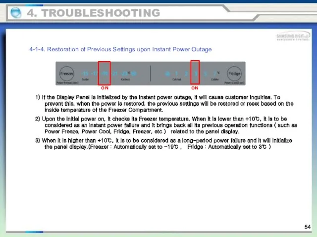
4-1-4. Restoration of Previous Settings upon Instant Power Outage
1) If the
4-1-4. Restoration of Previous Settings upon Instant Power Outage
1) If the
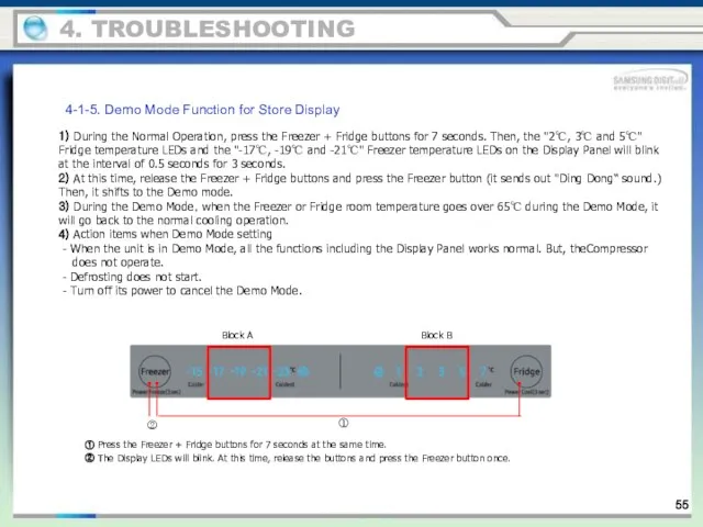
4-1-5. Demo Mode Function for Store Display
1) During the Normal Operation,
4-1-5. Demo Mode Function for Store Display
1) During the Normal Operation,
4-1-6. Option Setting Function
During the Normal Operation, press the Freezer +
4-1-6. Option Setting Function
During the Normal Operation, press the Freezer +
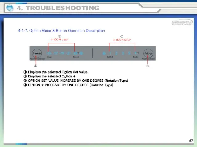
4-1-7. Option Mode & Button Operation Description
F-ROOM STEP
R-ROOM STEP
①
②
③
④
4. TROUBLESHOOTING
① Displays
4-1-7. Option Mode & Button Operation Description
F-ROOM STEP
R-ROOM STEP
①
②
③
④
4. TROUBLESHOOTING
① Displays
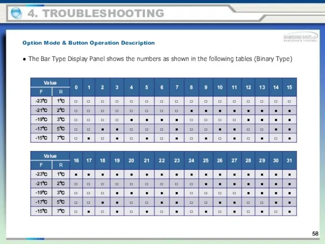
● The Bar Type Display Panel shows the numbers as shown
● The Bar Type Display Panel shows the numbers as shown
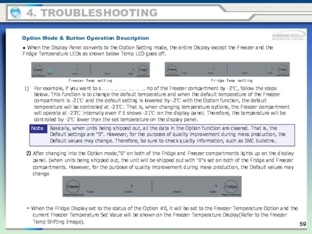
● When the Display Panel converts to the Option Setting mode,
● When the Display Panel converts to the Option Setting mode,
3) When "4" is set as shown in the Freezer Option
3) When "4" is set as shown in the Freezer Option
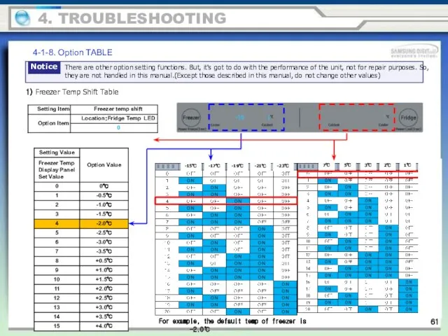
4-1-8. Option TABLE
1) Freezer Temp Shift Table
For example, the default temp
4-1-8. Option TABLE
1) Freezer Temp Shift Table
For example, the default temp
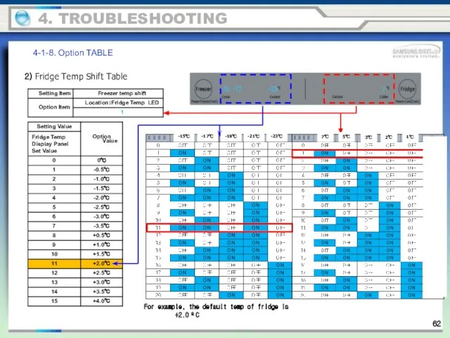
2) Fridge Temp Shift Table
For example, the default temp of fridge
2) Fridge Temp Shift Table
For example, the default temp of fridge
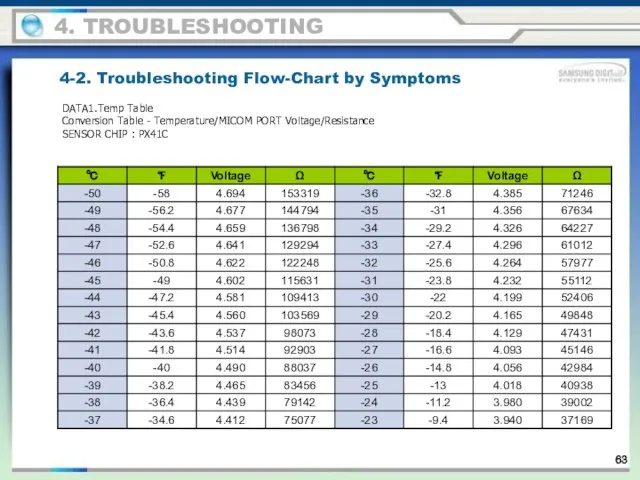
DATA1.Temp Table
Conversion Table - Temperature/MICOM PORT Voltage/Resistance
SENSOR CHIP : PX41C
4. TROUBLESHOOTING
4-2.
DATA1.Temp Table
Conversion Table - Temperature/MICOM PORT Voltage/Resistance
SENSOR CHIP : PX41C
4. TROUBLESHOOTING
4-2.
4. TROUBLESHOOTING
4-2. Troubleshooting Flow-Chart by Symptoms
4. TROUBLESHOOTING
4-2. Troubleshooting Flow-Chart by Symptoms
4. TROUBLESHOOTING
4-2. Troubleshooting Flow-Chart by Symptoms
4. TROUBLESHOOTING
4-2. Troubleshooting Flow-Chart by Symptoms
4. TROUBLESHOOTING
4-2. Troubleshooting Flow-Chart by Symptoms
4. TROUBLESHOOTING
4-2. Troubleshooting Flow-Chart by Symptoms
4-2-1. When Self-Diagnosis Error occurs
- The Display Panel shows the Sensor
4-2-1. When Self-Diagnosis Error occurs
- The Display Panel shows the Sensor
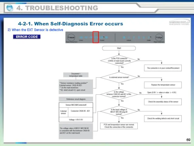
2) When the EXT Sensor is defective
4-2-1. When Self-Diagnosis Error
2) When the EXT Sensor is defective
4-2-1. When Self-Diagnosis Error
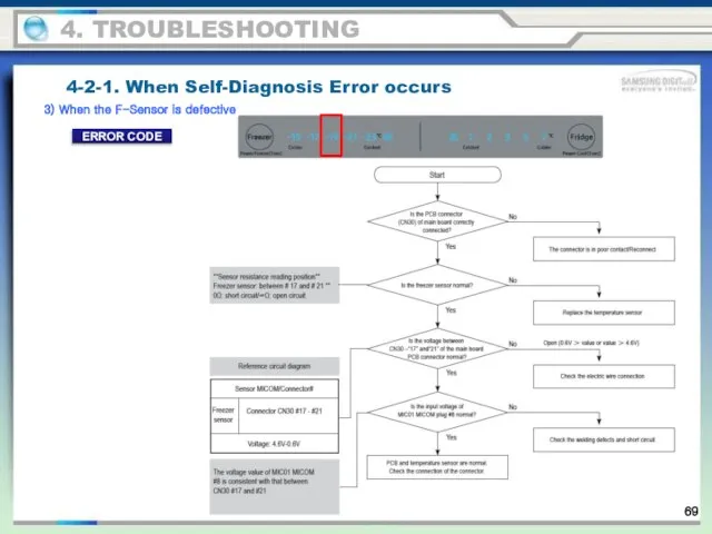
3) When the F-Sensor is defective
4-2-1. When Self-Diagnosis Error occurs
4. TROUBLESHOOTING
ERROR
3) When the F-Sensor is defective
4-2-1. When Self-Diagnosis Error occurs
4. TROUBLESHOOTING
ERROR
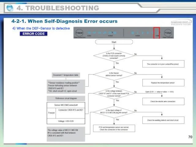
4) When the DEF-Sensor is defective
4-2-1. When Self-Diagnosis Error occurs
4. TROUBLESHOOTING
ERROR
4) When the DEF-Sensor is defective
4-2-1. When Self-Diagnosis Error occurs
4. TROUBLESHOOTING
ERROR
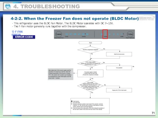
4-2-2. When the Freezer Fan does not operate (BLDC Motor)
1) F
4-2-2. When the Freezer Fan does not operate (BLDC Motor)
1) F
4. TROUBLESHOOTING
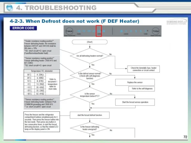
4-2-3. When Defrost does not work (F DEF Heater)
ERROR CODE
4. TROUBLESHOOTING
4-2-3. When Defrost does not work (F DEF Heater)
ERROR CODE
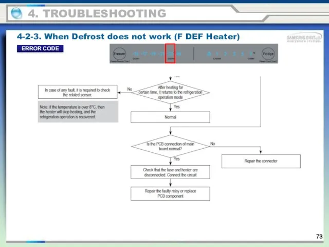
4. TROUBLESHOOTING
4-2-3. When Defrost does not work (F DEF Heater)
ERROR CODE
4. TROUBLESHOOTING
4-2-3. When Defrost does not work (F DEF Heater)
ERROR CODE
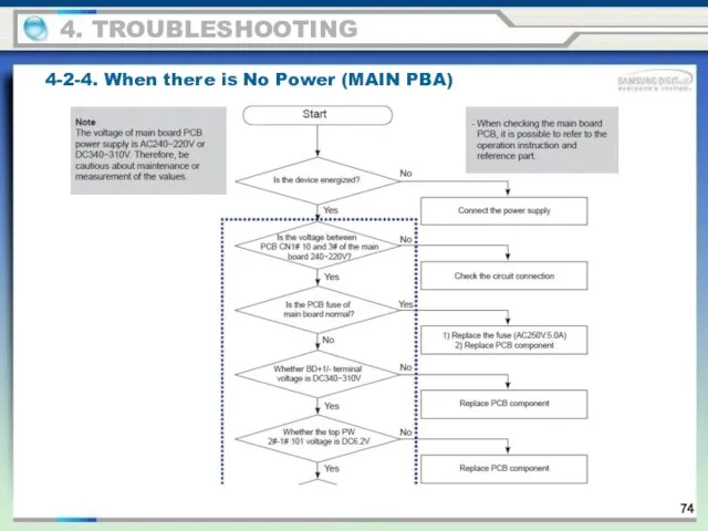
4-2-4. When there is No Power (MAIN PBA)
4. TROUBLESHOOTING
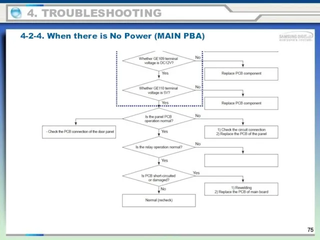
4-2-4. When there is No Power (MAIN PBA)
4. TROUBLESHOOTING
4-2-4. When there is No Power (MAIN PBA)
4. TROUBLESHOOTING
4-2-4. When there is No Power (MAIN PBA)
4. TROUBLESHOOTING
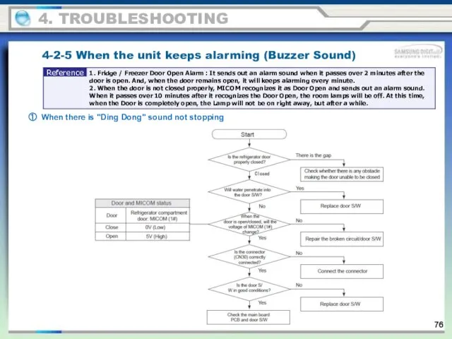
① When there is "Ding Dong" sound not stopping
4-2-5 When
① When there is "Ding Dong" sound not stopping
4-2-5 When
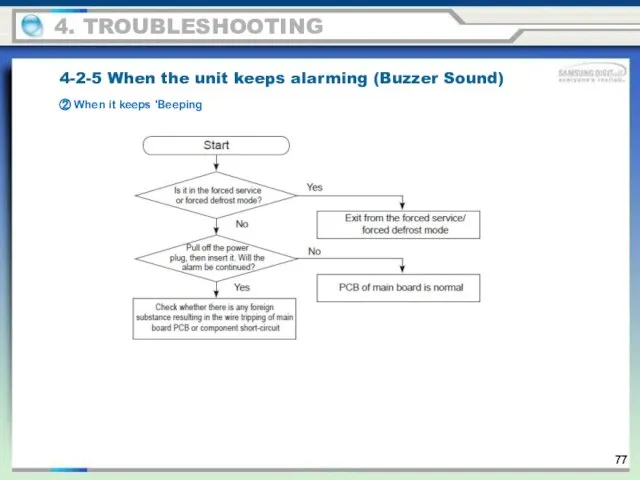
② When it keeps 'Beeping
4-2-5 When the unit keeps alarming
② When it keeps 'Beeping
4-2-5 When the unit keeps alarming
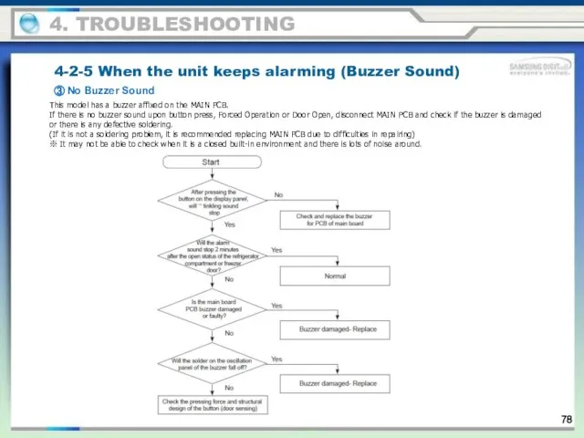
③ No Buzzer Sound
4-2-5 When the unit keeps alarming (Buzzer Sound)
4.
③ No Buzzer Sound
4-2-5 When the unit keeps alarming (Buzzer Sound)
4.
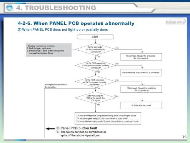
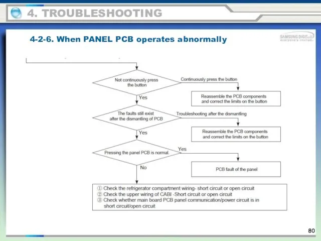
4-2-6. When PANEL PCB operates abnormally
① When PANEL PCB does not
4-2-6. When PANEL PCB operates abnormally
① When PANEL PCB does not
4-2-6. When PANEL PCB operates abnormally
4. TROUBLESHOOTING
4-2-6. When PANEL PCB operates abnormally
4. TROUBLESHOOTING
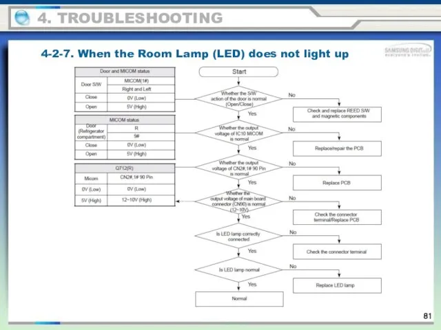
4-2-7. When the Room Lamp (LED) does not light up
4. TROUBLESHOOTING
4-2-7. When the Room Lamp (LED) does not light up
4. TROUBLESHOOTING
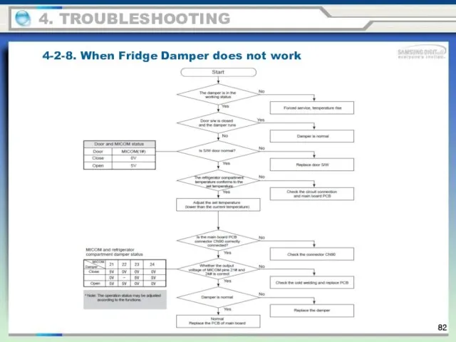
4-2-8. When Fridge Damper does not work
4. TROUBLESHOOTING
4-2-8. When Fridge Damper does not work
4. TROUBLESHOOTING
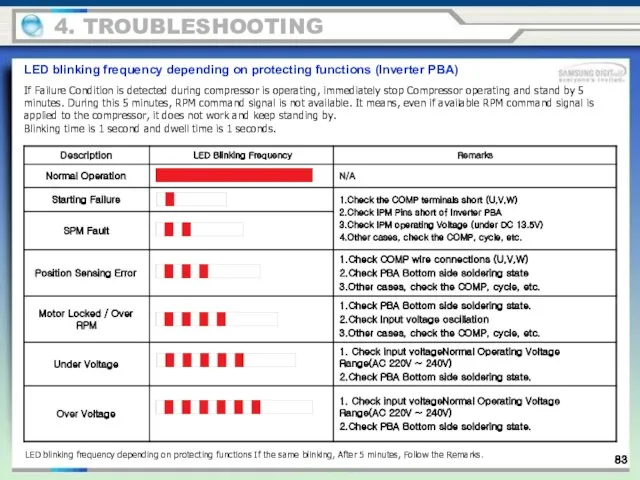
If Failure Condition is detected during compressor is operating, immediately stop
If Failure Condition is detected during compressor is operating, immediately stop
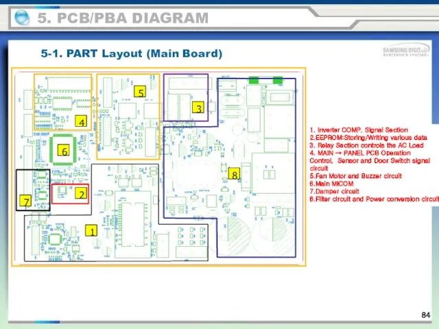
5-1. PART Layout (Main Board)
5. PCB/PBA DIAGRAM
1. Inverter COMP. Signal Section
2.EEPROM:Storing/Writing
5-1. PART Layout (Main Board)
5. PCB/PBA DIAGRAM
1. Inverter COMP. Signal Section
2.EEPROM:Storing/Writing
119
5-2. Connector Layout & Description (Main Board)
5. PCB/PBA DIAGRAM
119
5-2. Connector Layout & Description (Main Board)
5. PCB/PBA DIAGRAM
6. WIRING DIAGRAM
6. Wiring diagram
삼성의 허가 없이 문서 활용 불가
6. WIRING DIAGRAM
6. Wiring diagram
삼성의 허가 없이 문서 활용 불가
This document can not be used without Samsung's authorization
7. BLOCK DIAGRAM
7-1.
This document can not be used without Samsung's authorization
7. BLOCK DIAGRAM
7-1.
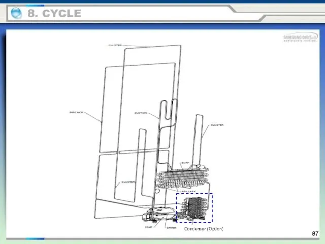
Condenser (Option)
8. CYCLE
87
Condenser (Option)
8. CYCLE
87
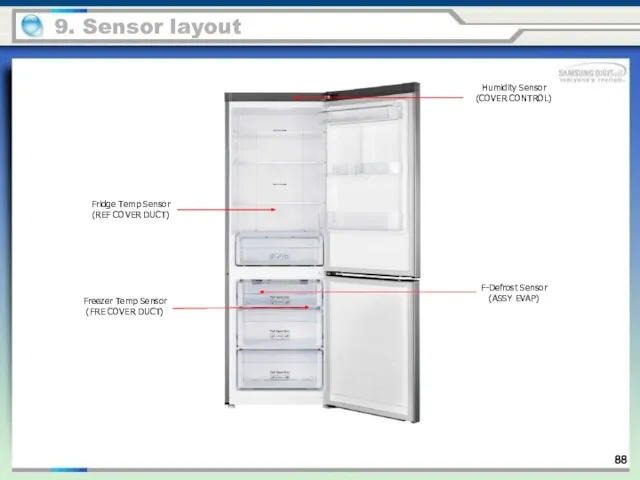
9. Sensor layout
Fridge Temp Sensor
(REF COVER DUCT)
Freezer Temp Sensor
(FRE COVER DUCT)
Humidity
9. Sensor layout
Fridge Temp Sensor
(REF COVER DUCT)
Freezer Temp Sensor
(FRE COVER DUCT)
Humidity
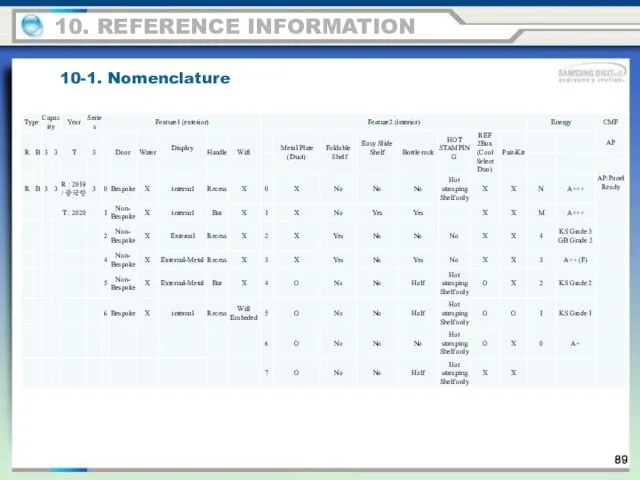
10-1. Nomenclature
10. REFERENCE INFORMATION
89
10-1. Nomenclature
10. REFERENCE INFORMATION
89
 презентация
 Что такое краеведение
 Электрическое оборудование тепловозов
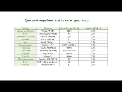 Данные о потребителях и их характеристиках
 Подготовка и проведение пеших и лыжных походов
 Л М-ды генерир. альтернатив Часть 1
 Методи, параметри оцінки та форми контролю якості в системах обробки ілюстративної інформації
 Классификация процессов и объектов автоматизации. Технологические требования к САУ ТП
 Overcoming line broadening in real-time pure shift NMR spectroscopy
 Города России
 20180315_okruglenie_des_drobey
 Как росла Церковь
 new style for ДомашкаГО by Dima Strapolov
 Устройства СВЧ и антенны
 20141116_prezentatsiya_microsoft_powerpoint_0
 Воевалко Виктория. Фотоальбом
 Какие бывают нитки? Как они используются?
 Цифровые системы передачи
 Международный день леса
 Сатирические образы человека
 Еврейский образ жизни
 Гибка тонколистового металла
 Robo дім роботів
 Мозаика из карандашной стружки
 20170122_poeticheskaya_stranitsa
 Безпечність та якість відновлених напоїв антистресової дії
 Предложения по развитию транспортно-дорожной сети района Лианозово
 Василий Макарович Шукшин. Село Сростки. Фотографии