- For classroom G5951 DC fundamentals

Содержание
- 2. DC motor: Introduction Design Physical way a DC motor works and equations Characteristics of a DC
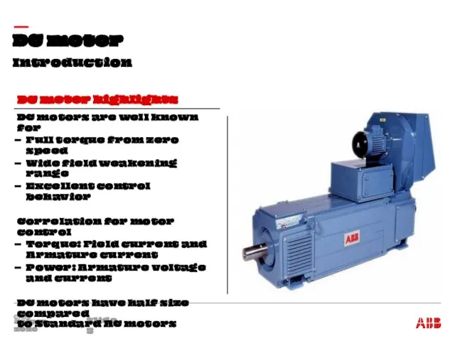
- 3. Introduction DC motor July 15, 2020 Slide DC motors are well known for Full torque from
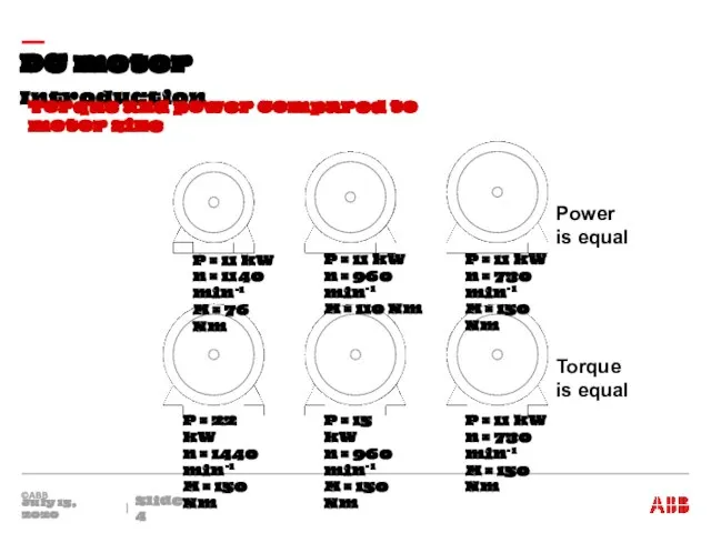
- 4. Introduction DC motor July 15, 2020 Slide Torque and power compared to motor size Power is
- 5. Design - Stator of a DC machine DC motor July 15, 2020 Slide Stator is the
- 6. Physical way a DC motor works DC motor July 15, 2020 Slide Stator of a 2
- 7. Physical way a DC motor works DC motor July 15, 2020 Slide Conductors have to be
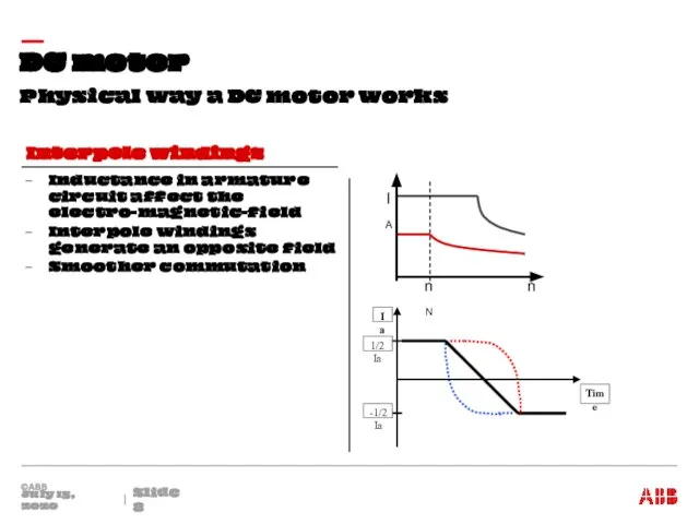
- 8. Physical way a DC motor works DC motor July 15, 2020 Slide Inductance in armature circuit
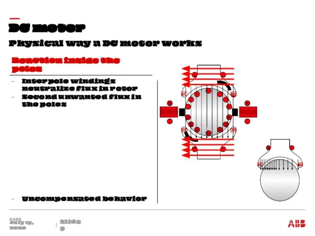
- 9. Physical way a DC motor works DC motor July 15, 2020 Slide Interpole windings neutralize flux
- 10. Physical way a DC motor works DC motor July 15, 2020 Slide Neutralizes effect of unwanted
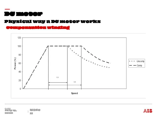
- 11. Physical way a DC motor works DC motor July 15, 2020 Slide Compensation winding
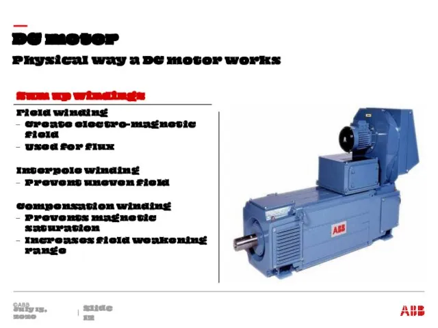
- 12. Physical way a DC motor works DC motor July 15, 2020 Slide Field winding Create electro-magnetic
- 13. Design DC motor July 15, 2020 Slide Shaft as center axis Armature winding Commutator connected with
- 14. Design DC motor July 15, 2020 Slide Commutator is used to transfer energy Fins are connected
- 15. Equations DC motor July 15, 2020 Slide Field circuit Armature circuit Circuit diagram Equations:
- 16. Drive’s characteristics DC motor July 15, 2020 Slide Characteristic of a DC machine Field weakening factor:
- 17. Compact DC machine (ABB DMI) – inculding terminals DC motor July 15, 2020 Slide Used as
- 18. ABB DMI motors DC motor July 15, 2020 Slide Air-cooled variant IC 06 IP 23 Water-cooled
- 19. General Layout DC drive July 15, 2020 Slide General layout Power Transformer Armature circuit Fuse Main
- 20. Armature Converter DC drive July 15, 2020 Slide 6-pulse thyristor bridge DC current AC line current
- 21. Armature converter DC drive July 15, 2020 Slide Voltages Phase voltage Phase to phase voltage Thyristor
- 22. Armature converter DC drive July 15, 2020 Slide 6-pulse thyristor bridge with a load Firing sequence:
- 23. Armature converter in “driving mode” DC drive July 15, 2020 Slide Positive voltage Firing angle smaller
- 24. Armature converter in “braking mode” DC drive July 15, 2020 Slide Negative voltage Firing angle greater
- 25. Armature converter in Shoot-through DC drive July 15, 2020 Slide DC drives are compromised by shoot-through
- 26. Line chokes Armature converter DC drive July 15, 2020 Slide Use of commutation chokes Mains Thyristor
- 27. Armature converter DC drive July 15, 2020 Slide Commutation in a converter Commutation from thyristor to
- 28. Armature converter DC drive July 15, 2020 Slide Commutation chokes limits di / dt during short
- 29. Armature converter DC drive July 15, 2020 Slide Commutation choke configurations PCC: Point of Common Coupling
- 30. Armature converter DC drive July 15, 2020 Slide Converter current in a DC drive Average current:
- 31. Calculations DC drive July 15, 2020 Slide Armature voltage of 2-quadrant drive 2-quadrant drive maximum motor
- 32. Calculations DC drive July 15, 2020 Slide Armature voltage of 4 quadrant drive 4-quadrant drive maximum
- 33. DC current and AC current Calculations DC drive July 15, 2020 Slide Calculate AC current with
- 34. Armature converter DC drive July 15, 2020 Slide Continuous and Discontinuous Armature Current Principle circuit diagram:
- 35. Max. regenerative voltage Armature converter DC drive July 15, 2020 Slide Usable working range of a
- 36. Properties and Applications DC drive July 15, 2020 Slide 2-Q or 4-Q drive? Properties 2-Quadrant Driving
- 37. Control structure DC drive July 15, 2020 Slide Diagram
- 39. Скачать презентацию
DC motor:
Introduction
Design
Physical way a DC motor works and equations
Characteristics of a
DC motor:
Introduction
Design
Physical way a DC motor works and equations
Characteristics of a
Introduction
DC motor
July 15, 2020
Slide
DC motors are well known for
Full torque
Introduction
DC motor
July 15, 2020
Slide
DC motors are well known for
Full torque
Introduction
DC motor
July 15, 2020
Slide
Torque and power compared to motor size
Power
Introduction
DC motor
July 15, 2020
Slide
Torque and power compared to motor size
Power

Design - Stator of a DC machine
DC motor
July 15, 2020
Slide
Stator
Design - Stator of a DC machine
DC motor
July 15, 2020
Slide
Stator

Physical way a DC motor works
DC motor
July 15, 2020
Slide
Stator of
Physical way a DC motor works
DC motor
July 15, 2020
Slide
Stator of

Physical way a DC motor works
DC motor
July 15, 2020
Slide
Conductors have
Physical way a DC motor works
DC motor
July 15, 2020
Slide
Conductors have
Physical way a DC motor works
DC motor
July 15, 2020
Slide
Inductance in
Physical way a DC motor works
DC motor
July 15, 2020
Slide
Inductance in
Physical way a DC motor works
DC motor
July 15, 2020
Slide
Interpole windings
Physical way a DC motor works
DC motor
July 15, 2020
Slide
Interpole windings

Physical way a DC motor works
DC motor
July 15, 2020
Slide
Neutralizes effect
Physical way a DC motor works
DC motor
July 15, 2020
Slide
Neutralizes effect
Physical way a DC motor works
DC motor
July 15, 2020
Slide
Compensation winding
Physical way a DC motor works
DC motor
July 15, 2020
Slide
Compensation winding
Physical way a DC motor works
DC motor
July 15, 2020
Slide
Field winding
Create
Physical way a DC motor works
DC motor
July 15, 2020
Slide
Field winding
Create

Design
DC motor
July 15, 2020
Slide
Shaft as center axis
Armature winding
Commutator connected with
Design
DC motor
July 15, 2020
Slide
Shaft as center axis
Armature winding
Commutator connected with

Design
DC motor
July 15, 2020
Slide
Commutator is used to transfer energy
Fins are
Design
DC motor
July 15, 2020
Slide
Commutator is used to transfer energy
Fins are

Equations
DC motor
July 15, 2020
Slide
Field circuit
Armature circuit
Circuit diagram
Equations:
Equations
DC motor
July 15, 2020
Slide
Field circuit
Armature circuit
Circuit diagram
Equations:

Drive’s characteristics
DC motor
July 15, 2020
Slide
Characteristic of a DC machine
Field
Drive’s characteristics
DC motor
July 15, 2020
Slide
Characteristic of a DC machine
Field
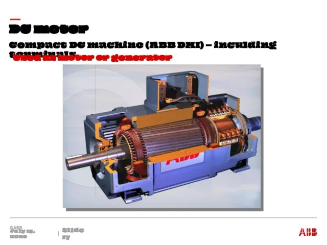
Compact DC machine (ABB DMI) – inculding terminals
DC motor
July 15, 2020
Slide
Compact DC machine (ABB DMI) – inculding terminals
DC motor
July 15, 2020
Slide
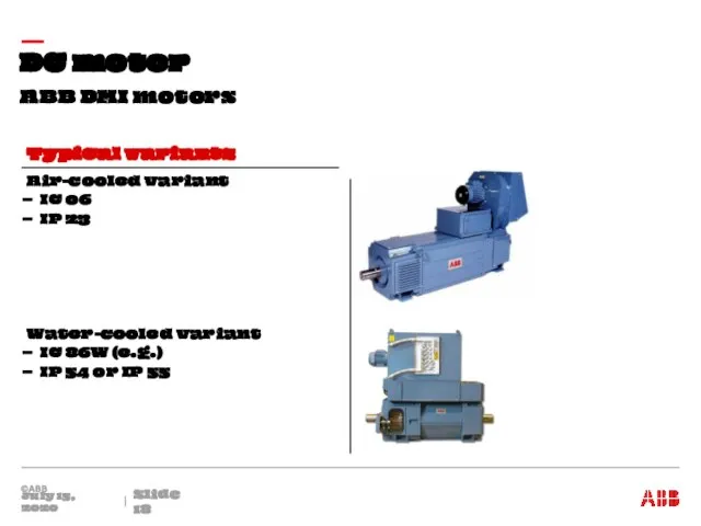
ABB DMI motors
DC motor
July 15, 2020
Slide
Air-cooled variant
IC 06
IP 23
Water-cooled variant
IC
ABB DMI motors
DC motor
July 15, 2020
Slide
Air-cooled variant
IC 06
IP 23
Water-cooled variant
IC
General Layout
DC drive
July 15, 2020
Slide
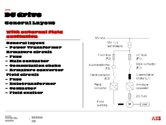
General layout
Power Transformer
Armature circuit
Fuse
Main contactor
Commutation choke
Armature
General Layout
DC drive
July 15, 2020
Slide
General layout
Power Transformer
Armature circuit
Fuse
Main contactor
Commutation choke
Armature
Armature Converter
DC drive
July 15, 2020
Slide
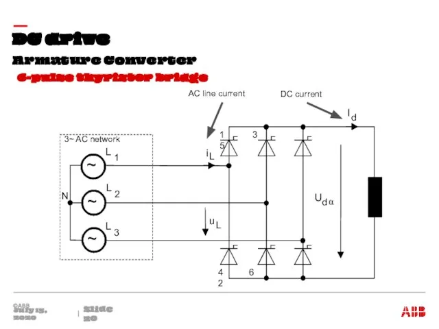
6-pulse thyristor bridge
DC current
AC line current
Armature Converter
DC drive
July 15, 2020
Slide
6-pulse thyristor bridge
DC current
AC line current
Armature converter
DC drive
July 15, 2020
Slide
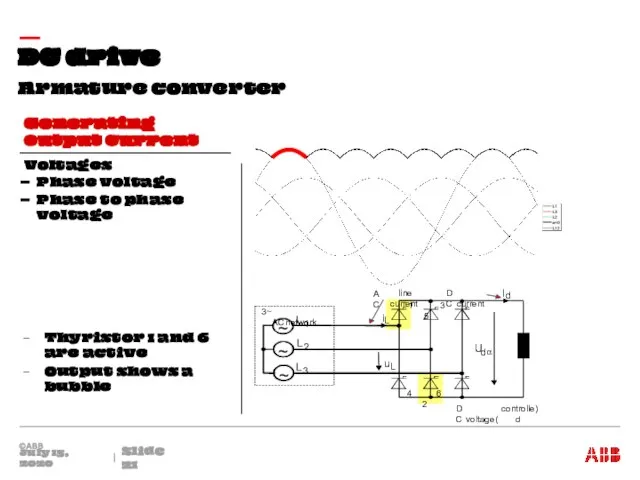
Voltages
Phase voltage
Phase to phase voltage
Thyristor 1
Armature converter
DC drive
July 15, 2020
Slide
Voltages
Phase voltage
Phase to phase voltage
Thyristor 1

Armature converter
DC drive
July 15, 2020
Slide
6-pulse thyristor bridge with a load
Firing
Armature converter
DC drive
July 15, 2020
Slide
6-pulse thyristor bridge with a load
Firing

Armature converter in “driving mode”
DC drive
July 15, 2020
Slide
Positive voltage
Firing angle
Armature converter in “driving mode”
DC drive
July 15, 2020
Slide
Positive voltage
Firing angle

Armature converter in “braking mode”
DC drive
July 15, 2020
Slide
Negative voltage
Firing angle
Armature converter in “braking mode”
DC drive
July 15, 2020
Slide
Negative voltage
Firing angle

Armature converter in Shoot-through
DC drive
July 15, 2020
Slide
DC drives are compromised
Armature converter in Shoot-through
DC drive
July 15, 2020
Slide
DC drives are compromised

Line chokes
Armature converter
DC drive
July 15, 2020
Slide
Use of commutation chokes
Mains
Thyristor bridge
Line chokes
Armature converter
DC drive
July 15, 2020
Slide
Use of commutation chokes
Mains
Thyristor bridge
Armature converter
DC drive
July 15, 2020
Slide
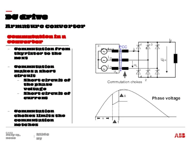
Commutation in a converter
Commutation from thyristor
Armature converter
DC drive
July 15, 2020
Slide
Commutation in a converter
Commutation from thyristor

Armature converter
DC drive
July 15, 2020
Slide
Commutation chokes limits di / dt
Armature converter
DC drive
July 15, 2020
Slide
Commutation chokes limits di / dt
Armature converter
DC drive
July 15, 2020
Slide
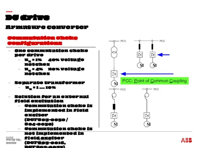
Commutation choke configurations
PCC: Point of Common
Armature converter
DC drive
July 15, 2020
Slide
Commutation choke configurations
PCC: Point of Common

Armature converter
DC drive
July 15, 2020
Slide
Converter current in a DC drive
Average
Armature converter
DC drive
July 15, 2020
Slide
Converter current in a DC drive
Average
Calculations
DC drive
July 15, 2020
Slide
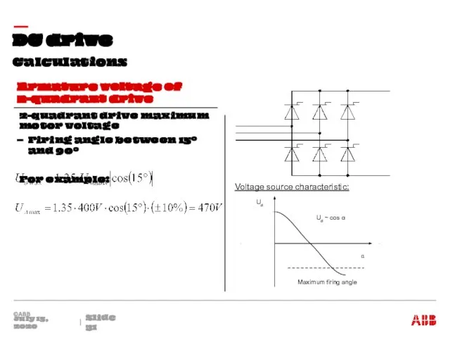
Armature voltage of 2-quadrant drive
2-quadrant drive maximum
Calculations
DC drive
July 15, 2020
Slide
Armature voltage of 2-quadrant drive
2-quadrant drive maximum
Calculations
DC drive
July 15, 2020
Slide
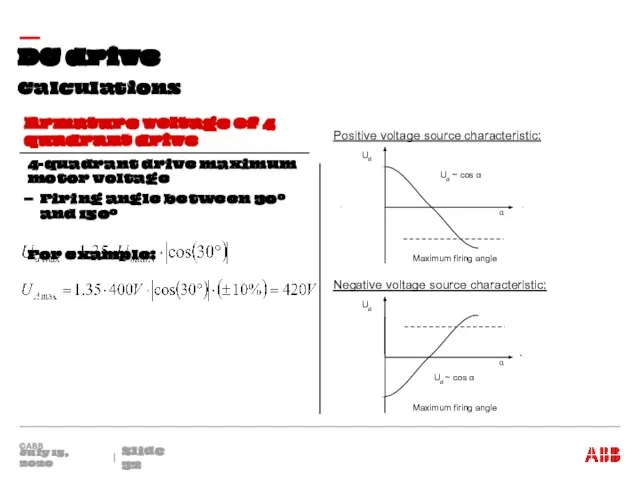
Armature voltage of 4 quadrant drive
4-quadrant
Calculations
DC drive
July 15, 2020
Slide
Armature voltage of 4 quadrant drive
4-quadrant

DC current and AC current
Calculations
DC drive
July 15, 2020
Slide
Calculate AC
DC current and AC current
Calculations
DC drive
July 15, 2020
Slide
Calculate AC

Armature converter
DC drive
July 15, 2020
Slide
Continuous and Discontinuous Armature Current
Principle circuit
Armature converter
DC drive
July 15, 2020
Slide
Continuous and Discontinuous Armature Current
Principle circuit

Max. regenerative voltage
Armature converter
DC drive
July 15, 2020
Slide
Usable working range of
Max. regenerative voltage
Armature converter
DC drive
July 15, 2020
Slide
Usable working range of
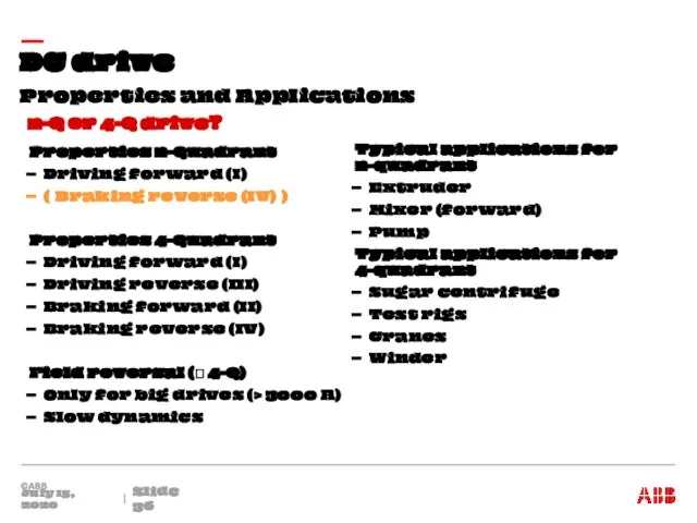
Properties and Applications
DC drive
July 15, 2020
Slide
2-Q or 4-Q drive?
Properties
Properties and Applications
DC drive
July 15, 2020
Slide
2-Q or 4-Q drive?
Properties
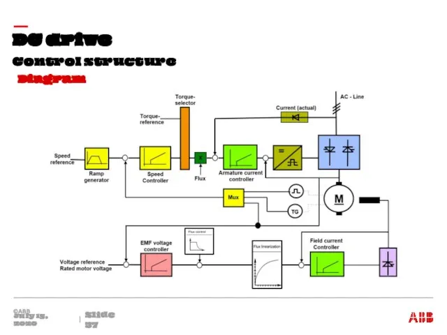
Control structure
DC drive
July 15, 2020
Slide
Diagram
Control structure
DC drive
July 15, 2020
Slide
Diagram
 Автоматизация производства в легкой промышленности
 Беспроводные и 4-х проводные видеодомофоны, многоабонентские домофонные системы и системы сигнализаций
 Технология сверления заготовок на настольном сверлильном станке
 Пищеварение в тонкой и толстой кишке. Всасывание. Моторная функция пищеварительного тракта
 20171119_kompleknyy_analiz_teksta
 Информация о городских новогодних и рождественских мероприятиях
 Понятие плитки и ее применение
 Техника безопасности на производстве
 Платы макетно-отладочные
 Архитектура ПО
 Казанский зооботсад
 Международная премия
 Ковровые изделия
 Охранять природу – значит охранять Родину
 Жанры ИЗО для учащихся по программе Живопись. Рисунок 3 год обучения
 20160118_bludnyy_syn
 Презентация Новый город финал
 20130316_dobroe_otnoshenie_k_okruzhayushchim_-_2_chast
 Гигиена жилища
 Цвета флага ДНР
 Экскурсия в Оружейную палату Московского кремля
 20120301_longfello111
 8 марта 2014
 20120328_prava_i_polnomochiya_glavy_gosudarstva
 Эскизная компоновка зубчатого редуктора. Редуктор цилиндрический одноступенчатый горизонтальный
 20160215_novoe_i_noveyshee_vremya
 20170125_my_so_zvukom_ch_igraem_
 Арматура и арматурные изделия