- How to draw the tolerance zones of transition fit (Seminar 2)

Содержание
- 2. Step 1: Example We have two joint parts (details): shaft bush (we have empty place for
- 3. Step 2: Calculation of shaft dimensions We know two limited deviations: Upper deviation: es=dmax- dn Lower
- 4. Step 3: Calculation of bush dimensions We know two limited deviations: Upper deviation: ES=Dmax- Dn Lower
- 5. Step 4: Drawing zero line
- 6. Step 5: Drawing the shaft tolerance zone
- 7. Step 6: Drawing the hole tolerance zone
- 8. Step 7: Clearances and interferences of transition fit For transition fits we have both clearances and
- 9. Step 8: Calculation of Smax
- 10. Step 9: Calculation of Nmax
- 12. Скачать презентацию
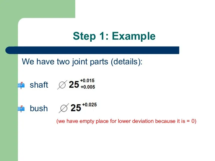
Step 1: Example
We have two joint parts (details):
shaft
bush
(we have empty
Step 1: Example
We have two joint parts (details):
shaft
bush
(we have empty
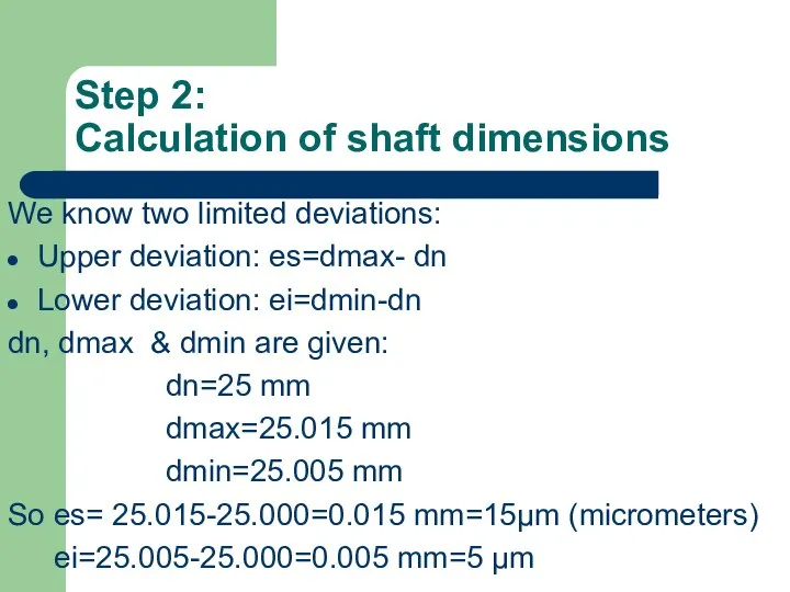
Step 2:
Calculation of shaft dimensions
We know two limited deviations:
Upper deviation:
Step 2:
Calculation of shaft dimensions
We know two limited deviations:
Upper deviation:
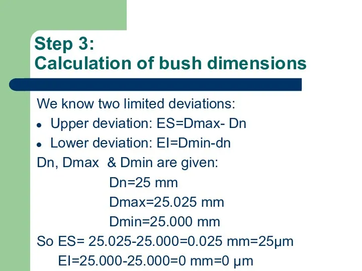
Step 3:
Calculation of bush dimensions
We know two limited deviations:
Upper deviation:
Step 3:
Calculation of bush dimensions
We know two limited deviations:
Upper deviation:
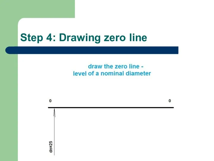
Step 4: Drawing zero line
Step 4: Drawing zero line
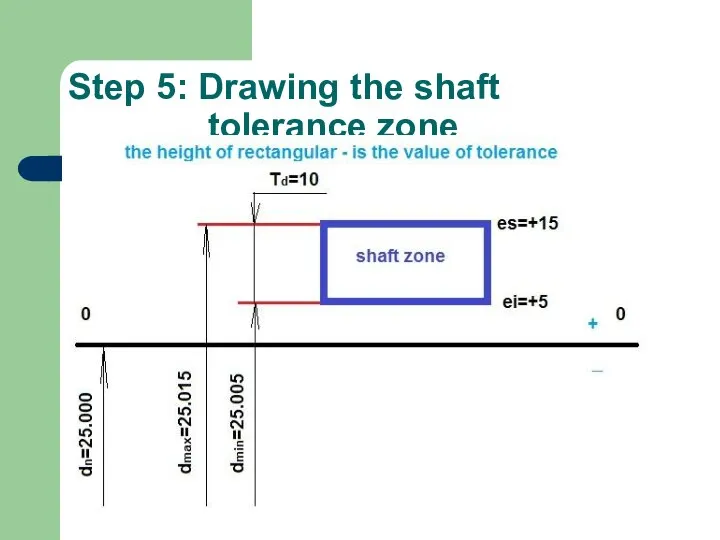
Step 5: Drawing the shaft
tolerance zone
Step 5: Drawing the shaft
tolerance zone
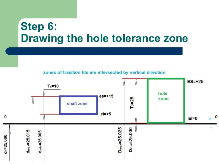
Step 6:
Drawing the hole tolerance zone
Step 6:
Drawing the hole tolerance zone
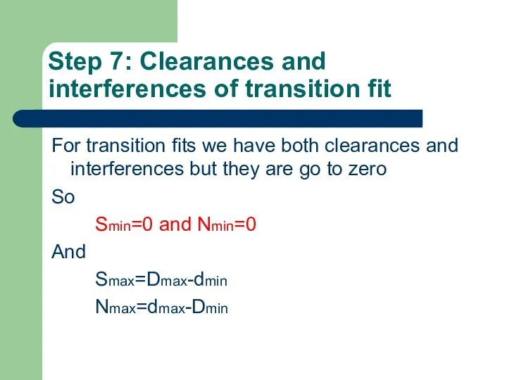
Step 7: Clearances and interferences of transition fit
For transition fits we
Step 7: Clearances and interferences of transition fit
For transition fits we
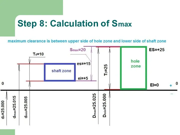
Step 8: Calculation of Smax
Step 8: Calculation of Smax
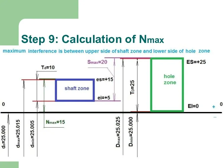
Step 9: Calculation of Nmax
Step 9: Calculation of Nmax
 Правка тонколистового металла и проволоки
 От воспоминаний всем теплей, нам от них нельзя не улыбнуться
 20150121_logopedicheskoe_zanyatie._analiz_i_redaktirovanie_pismennykh_rabot
 Не торопи меня, мой календарь
 Письмо для Вани Жукова
 Igra_po_finansam
 Курсовая работа
 Керамические стеновые материалы
 Проект Музейная цифровая лаборатория
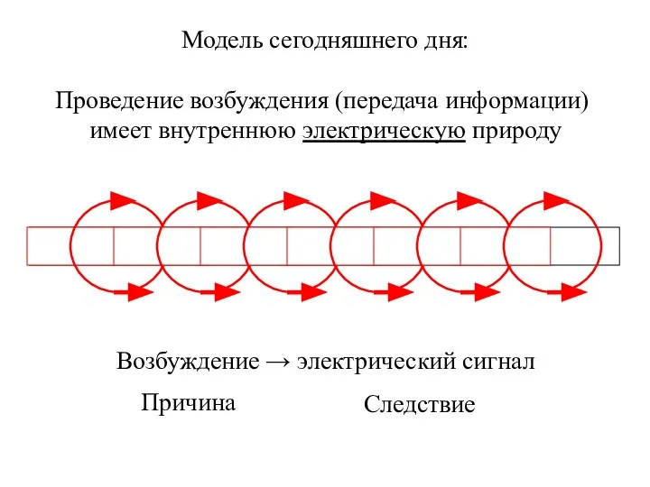 Импульсный ток
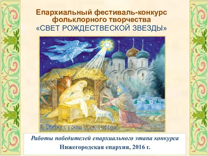 Епархиальный фестиваль-конкурс фольклорного творчества свет рождествеской звезды
 Зеленый шаблон. Российское общество Знание
 продолжение
 Используемые инструменты. Виды клеев
 Православные святыни и святые Курской земли
 Микросхемотехника. Занятие № 34
 20131219_mezhdunarodnye_otnosheniya_0
 Современное состояние и перспективы развития глемпинга на территории России
 Заявка на участие в отборе перспективных биотехнологических проектов. Шаблон
 презентация 2
 презентация
 “Базові команди адміністрування ОС.”
 01-intr
 HollySys PLC Introduction-V1.2-Русский
 Вязание домика крючком
 Фейковые новости: кто привлекается к ответственности за их распространение
 20130321_frebel_0
 Основы технологических процессов в художественном производстве (Практические занятия)