- Revision history

Содержание
- 2. Symbols Important Inspect Next Slide Previous Slide Menu Link to Quality Database Quality Stamp
- 3. SELECT MODEL TO BE TESTED MENU AR2 Standard AR2 Geo AR2 Geo Cell AR2 Geo Cell
- 4. Set Wireless Test Configuration Insert Archer 2 Test USB drive into your PC. Go into the
- 5. Equipment Required – GC Items are not to scale Initial Setup for Wi-Fi/BT Tests (press ESC
- 6. Equipment Required – GBC Items are not to scale Initial Setup for Wi-Fi/BT Tests (press ESC
- 7. Equipment Required – Std & Geo Items are not to scale Link to Initial Setup for
- 8. Equipment Required - GB Items are not to scale Link to Initial Setup for Wi-Fi/BT Tests
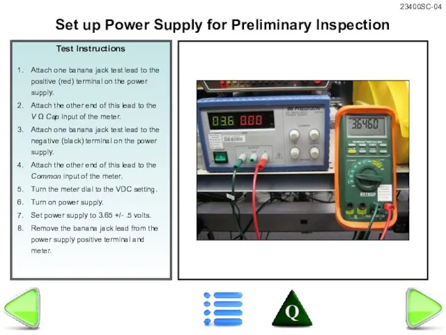
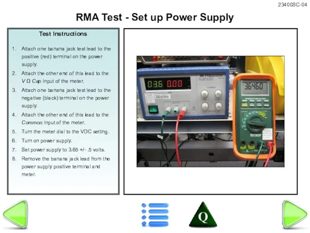
- 9. Test Instructions Attach one banana jack test lead to the positive (red) terminal on the power
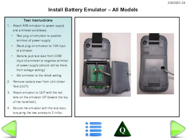
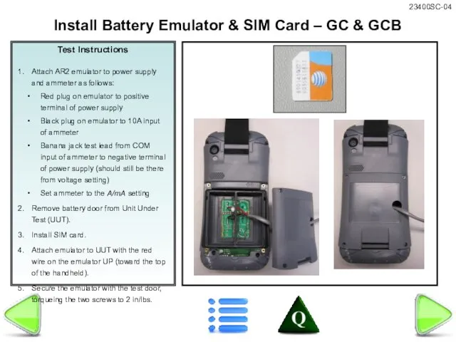
- 10. Test Instructions Attach AR2 emulator to power supply and ammeter as follows: Red plug on emulator
- 11. Test Instructions Attach AR2 emulator to power supply and ammeter as follows: Red plug on emulator
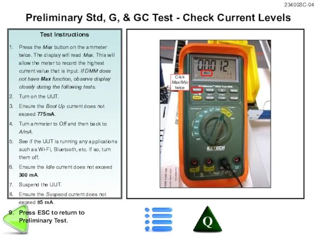
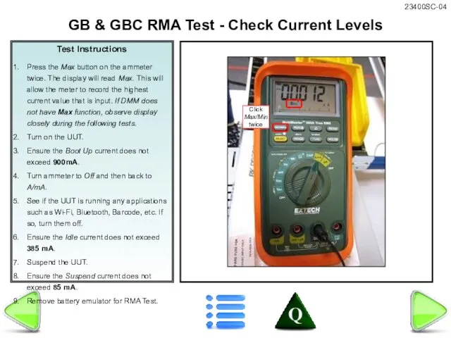
- 12. Test Instructions Press the Max button on the ammeter twice. The display will read Max. This
- 13. Test Instructions Press the Max button on the ammeter twice. The display will read Max. This
- 14. Test Instructions Attach one banana jack test lead to the positive (red) terminal on the power
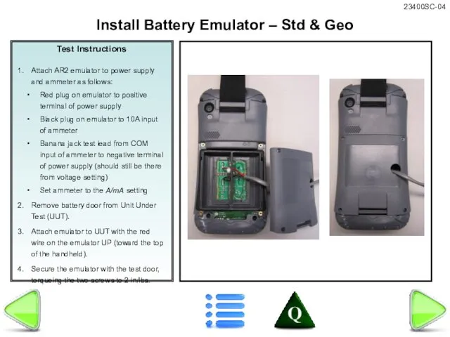
- 15. Test Instructions Attach AR2 emulator to power supply and ammeter as follows: Red plug on emulator
- 16. Test Instructions Press the Max button on the ammeter twice. The display will read Max. This
- 17. Test Instructions Press the Max button on the ammeter twice. The display will read Max. This
- 18. Test Instructions Attach AR2 emulator to power supply and ammeter as follows: Red plug on emulator
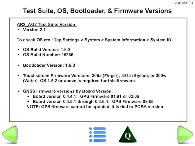
- 19. Test Suite, OS, Bootloader, & Firmware Versions AR2_AG2 Test Suite Version: Version 2.1 To check OS
- 20. Std, G, & GC Preliminary Inspection Visually inspect unit for obvious damage or wear (scratched or
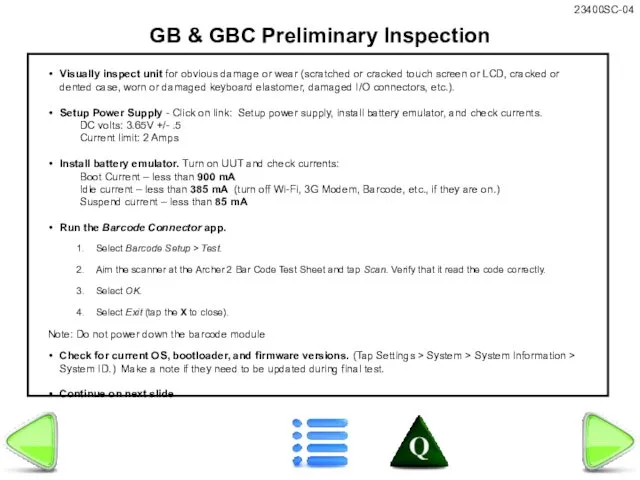
- 21. GB & GBC Preliminary Inspection Visually inspect unit for obvious damage or wear (scratched or cracked
- 22. Std, G, & GC - Preliminary Inspection, continued Turn on the Wi-Fi and verify that Wi-Fi
- 23. GC & GCB - Preliminary Inspection, continued Test touch screen function. Tap on Start > Notes.
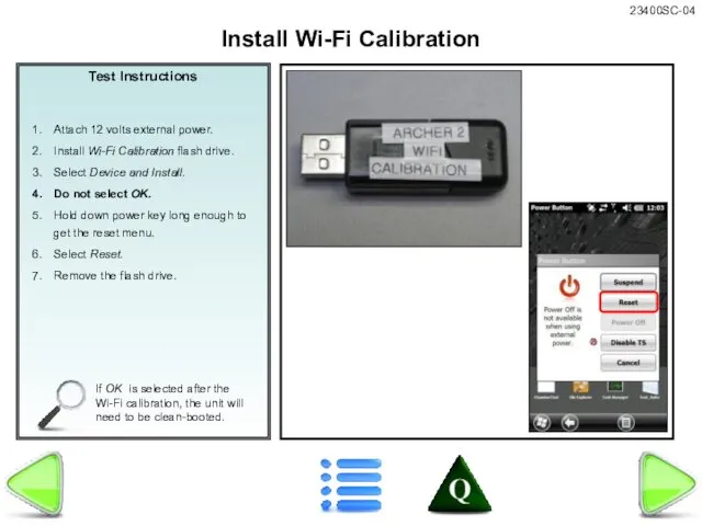
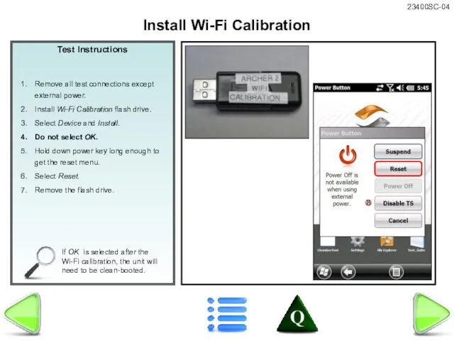
- 24. Test Instructions If OK is selected after the Wi-Fi calibration, the unit will need to be
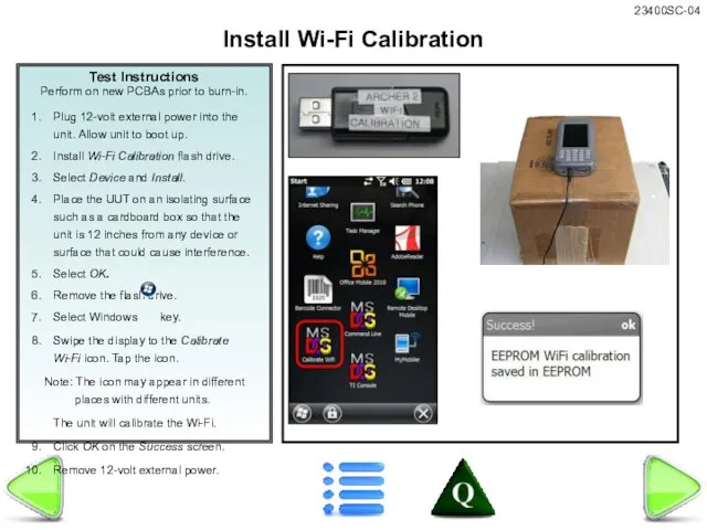
- 25. Test Instructions Perform on new PCBAs prior to burn-in. Install Wi-Fi Calibration
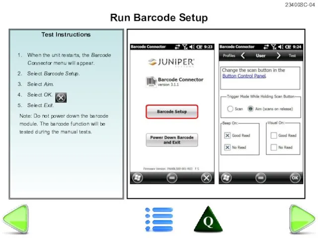
- 26. Test Instructions When the unit restarts, the Barcode Connector menu will appear. Select Barcode Setup. Select
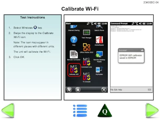
- 27. Test Instructions Calibrate Wi-Fi
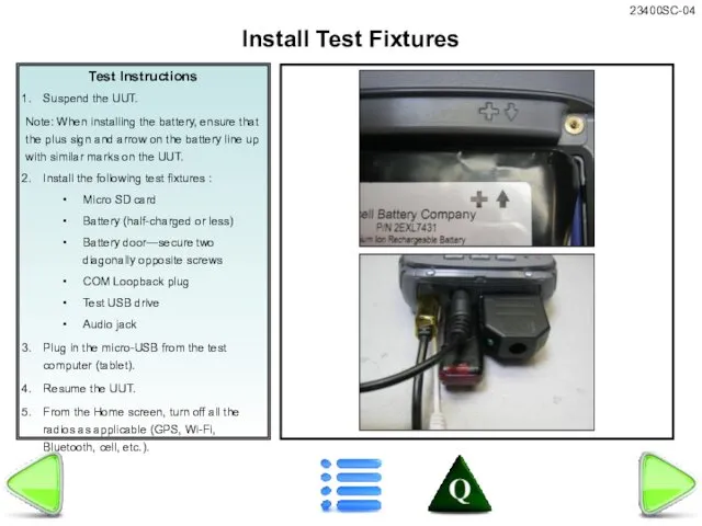
- 28. Test Instructions Suspend the UUT. Note: When installing the battery, ensure that the plus sign and
- 29. Test Instructions Attach battery door using all four screws. If Gore-Tex patch is not already in
- 30. Test Instructions Place the unit in the chamber. Insert 12-volt external power into the unit. Allow
- 31. Test Instructions Insert the Chamber Test (v1.1) flash drive into the USB port. After the tests
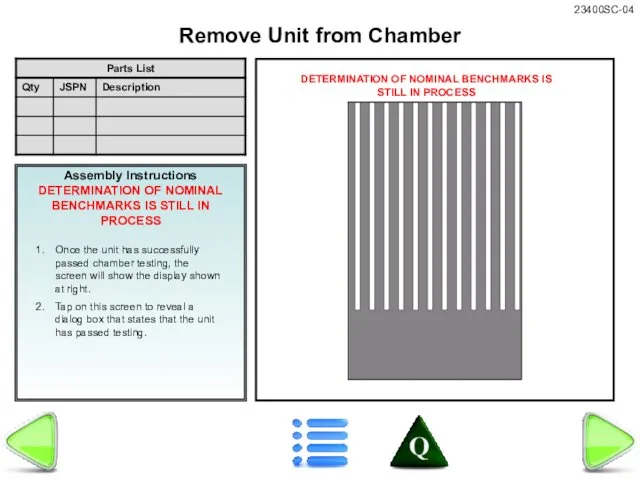
- 32. Assembly Instructions DETERMINATION OF NOMINAL BENCHMARKS IS STILL IN PROCESS Once the unit has successfully passed
- 33. Test Instructions Note: When installing the battery, ensure that the plus sign and arrow on the
- 34. Test Instructions If OK is selected after the Wi-Fi calibration, the unit will need to be
- 35. Test Instructions Calibrate Wi-Fi
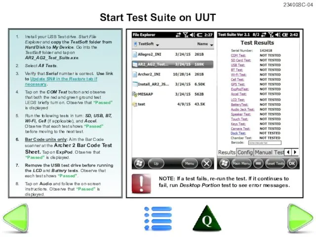
- 36. Install your USB Test drive. Start File Explorer and copy the TestSoft folder from Hard Disk
- 37. Bar Code Test Press ESC to return
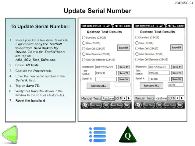
- 38. To Update Serial Number: Install your USB Test drive. Start File Explorer and copy the TestSoft
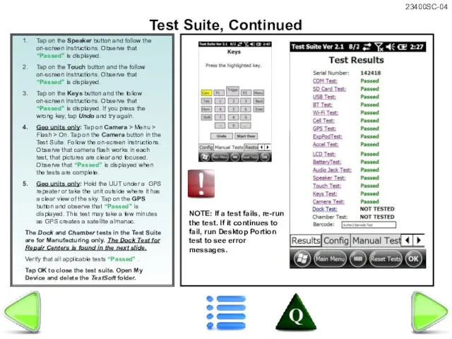
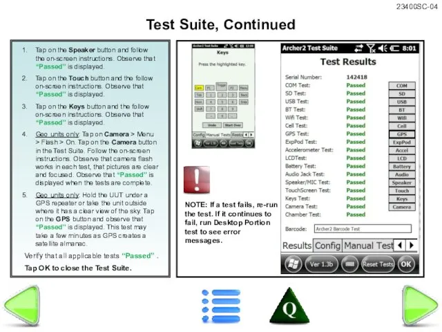
- 39. Tap on the Speaker button and follow the on-screen instructions. Observe that “Passed” is displayed. Tap
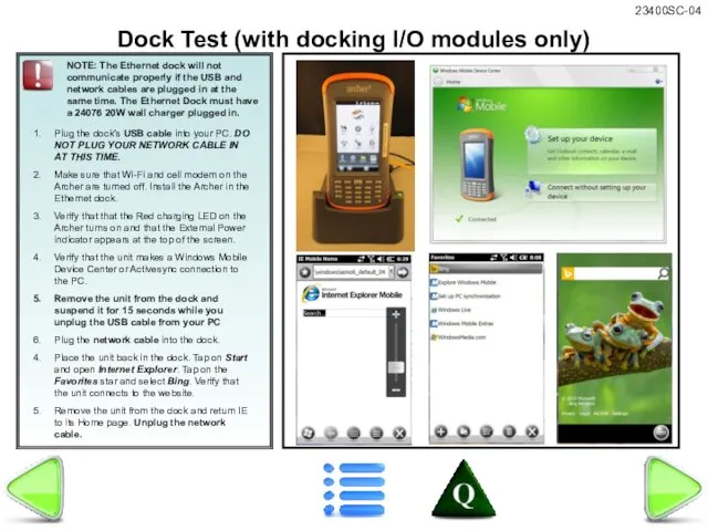
- 40. Plug the dock’s USB cable into your PC. DO NOT PLUG YOUR NETWORK CABLE IN AT
- 41. Tap on the Speaker button and follow the on-screen instructions. Observe that “Passed” is displayed. Tap
- 42. Perform Wi-Fi configuration & Model update if you replaced the Main PCBA. Install USB Test drive
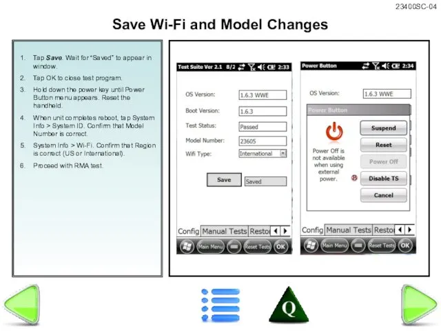
- 43. Tap Save. Wait for “Saved” to appear in window. Tap OK to close test program. Hold
- 44. Verify that OS, bootloader, and firmware versions are current. To update, connect UUT to your PC
- 45. The 306a, 301a, & 300w touch screen firmware comes standard with OS 1.5.2. You should never
- 46. Confirm that cell modem & SIM card are working. Note: This test requires a functioning SIM
- 47. NOTE: If you have replaced a 24771 CDMA modem, the MEID numbers from the new modem
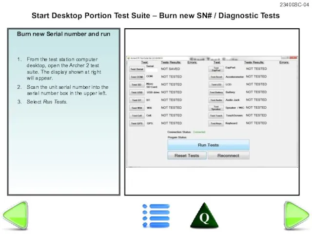
- 48. Burn new Serial number and run From the test station computer desktop, open the Archer 2
- 49. Burn Serial Number on New PCBA - Diagnostics Test Connect UUT to your PC with USB
- 50. If unit fails manual tests, use Desktop Test Suite to view diagnostic error messages: Install required
- 51. Ref: 12333-** Bubble-Test.TST.doc Perform leak test on repaired unit before performing other tests. Refer to the
- 52. Verify product label is correct. Install new label as needed. REF: 23400-** AR2 SC FCF document
- 53. Final Inspection Remove all test fixtures. Do not forget test batteries and test SD cards. Reinstall
- 54. WMDC Connection Test Setup Windows Mobile Device Center: Start Windows Mobile Device Center. Click on Mobile
- 55. Assembly Instructions 1. Copy all files in the FC500 JSCAB Install folder to the root directory
- 56. Assembly Instructions This is to have the assembler check something after the step is done Place
- 57. Assembly Instructions This is to have the assembler check something after the step is done Place
- 58. Assembly Instructions This is to have the assembler check something after the step is done Place
- 60. Скачать презентацию
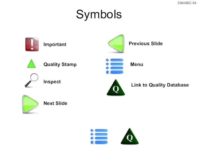
Symbols
Important
Inspect
Next Slide
Previous Slide
Menu
Link to Quality Database
Quality Stamp
Symbols
Important
Inspect
Next Slide
Previous Slide
Menu
Link to Quality Database
Quality Stamp
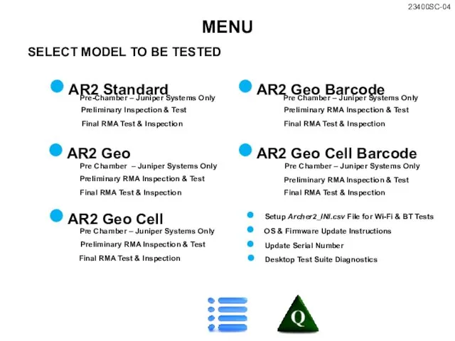
SELECT MODEL TO BE TESTED
MENU
AR2 Standard
AR2 Geo
AR2 Geo Cell
AR2 Geo Cell
SELECT MODEL TO BE TESTED
MENU
AR2 Standard
AR2 Geo
AR2 Geo Cell
AR2 Geo Cell
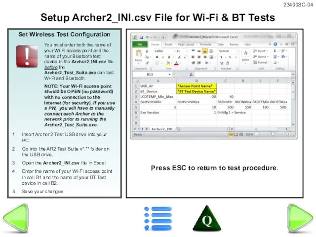
Set Wireless Test Configuration
Insert Archer 2 Test USB drive into your
Set Wireless Test Configuration
Insert Archer 2 Test USB drive into your
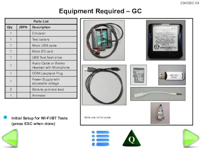
Equipment Required – GC
Items are not to scale
Initial Setup for Wi-Fi/BT
Equipment Required – GC
Items are not to scale
Initial Setup for Wi-Fi/BT
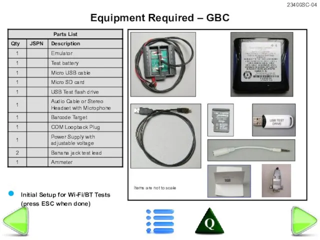
Equipment Required – GBC
Items are not to scale
Initial Setup for Wi-Fi/BT
Equipment Required – GBC
Items are not to scale
Initial Setup for Wi-Fi/BT
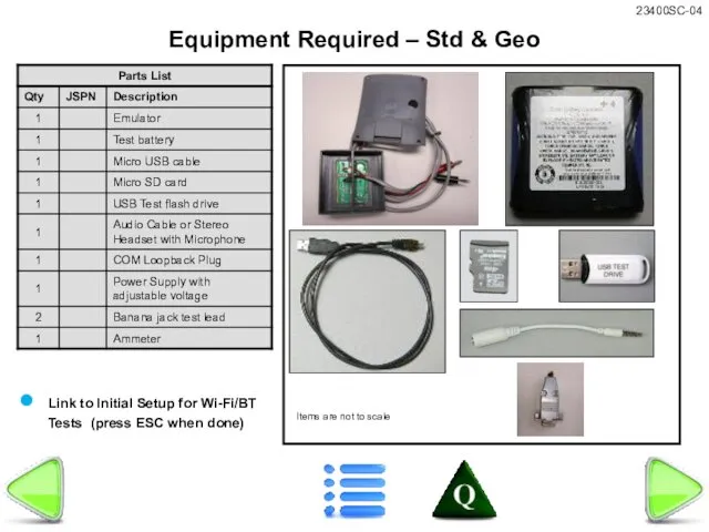
Equipment Required – Std & Geo
Items are not to scale
Link to
Equipment Required – Std & Geo
Items are not to scale
Link to
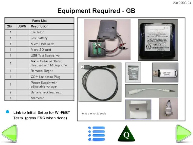
Equipment Required - GB
Items are not to scale
Link to Initial Setup
Equipment Required - GB
Items are not to scale
Link to Initial Setup
Test Instructions
Attach one banana jack test lead to the positive (red)
Test Instructions
Attach one banana jack test lead to the positive (red)

Test Instructions
Attach AR2 emulator to power supply and ammeter as follows:
Red
Test Instructions
Attach AR2 emulator to power supply and ammeter as follows:
Red
Test Instructions
Attach AR2 emulator to power supply and ammeter as follows:
Red
Test Instructions
Attach AR2 emulator to power supply and ammeter as follows:
Red
Test Instructions
Press the Max button on the ammeter twice. The display
Test Instructions
Press the Max button on the ammeter twice. The display

Test Instructions
Press the Max button on the ammeter twice. The display
Test Instructions
Press the Max button on the ammeter twice. The display
Test Instructions
Attach one banana jack test lead to the positive (red)
Test Instructions
Attach one banana jack test lead to the positive (red)
Test Instructions
Attach AR2 emulator to power supply and ammeter as follows:
Red
Test Instructions
Attach AR2 emulator to power supply and ammeter as follows:
Red

Test Instructions
Press the Max button on the ammeter twice. The display
Test Instructions
Press the Max button on the ammeter twice. The display
Test Instructions
Press the Max button on the ammeter twice. The display
Test Instructions
Press the Max button on the ammeter twice. The display
Test Instructions
Attach AR2 emulator to power supply and ammeter as follows:
Red
Test Instructions
Attach AR2 emulator to power supply and ammeter as follows:
Red
Test Suite, OS, Bootloader, & Firmware Versions
AR2_AG2 Test Suite Version:
Version 2.1
To
Test Suite, OS, Bootloader, & Firmware Versions
AR2_AG2 Test Suite Version:
Version 2.1
To

Std, G, & GC Preliminary Inspection
Visually inspect unit for obvious damage
Std, G, & GC Preliminary Inspection
Visually inspect unit for obvious damage
GB & GBC Preliminary Inspection
Visually inspect unit for obvious damage or
GB & GBC Preliminary Inspection
Visually inspect unit for obvious damage or
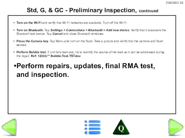
Std, G, & GC - Preliminary Inspection, continued
Turn on the Wi-Fi
Std, G, & GC - Preliminary Inspection, continued
Turn on the Wi-Fi

GC & GCB - Preliminary Inspection, continued
Test touch screen function. Tap
GC & GCB - Preliminary Inspection, continued
Test touch screen function. Tap
Test Instructions
If OK is selected after the Wi-Fi calibration, the unit
Test Instructions
If OK is selected after the Wi-Fi calibration, the unit
Test Instructions
Perform on new PCBAs prior to burn-in.
Install Wi-Fi Calibration
Test Instructions
Perform on new PCBAs prior to burn-in.
Install Wi-Fi Calibration
Test Instructions
When the unit restarts, the Barcode Connector menu will appear.
Test Instructions
When the unit restarts, the Barcode Connector menu will appear.

Test Instructions
Calibrate Wi-Fi
Test Instructions
Calibrate Wi-Fi
Test Instructions
Suspend the UUT.
Note: When installing the battery, ensure that the
Test Instructions
Suspend the UUT.
Note: When installing the battery, ensure that the

Test Instructions
Attach battery door using all four screws.
If Gore-Tex patch is
Test Instructions
Attach battery door using all four screws.
If Gore-Tex patch is

Test Instructions
Place the unit in the chamber.
Insert 12-volt external power into
Test Instructions
Place the unit in the chamber.
Insert 12-volt external power into

Test Instructions
Insert the Chamber Test (v1.1) flash drive into the USB
Test Instructions
Insert the Chamber Test (v1.1) flash drive into the USB
Assembly Instructions
DETERMINATION OF NOMINAL BENCHMARKS IS STILL IN PROCESS
Once the unit
Assembly Instructions
DETERMINATION OF NOMINAL BENCHMARKS IS STILL IN PROCESS
Once the unit

Test Instructions
Note: When installing the battery, ensure that the plus sign
Test Instructions
Note: When installing the battery, ensure that the plus sign
Test Instructions
If OK is selected after the Wi-Fi calibration, the unit
Test Instructions
If OK is selected after the Wi-Fi calibration, the unit
Test Instructions
Calibrate Wi-Fi
Test Instructions
Calibrate Wi-Fi
Install your USB Test drive. Start File Explorer and copy the
Install your USB Test drive. Start File Explorer and copy the

Bar Code Test
Press ESC to return
Bar Code Test
Press ESC to return
To Update Serial Number:
Install your USB Test drive. Start File Explorer
Install your USB Test drive. Start File Explorer
Tap on the Speaker button and follow the on-screen instructions. Observe
Tap on the Speaker button and follow the on-screen instructions. Observe
Plug the dock’s USB cable into your PC. DO NOT PLUG
Plug the dock’s USB cable into your PC. DO NOT PLUG
Tap on the Speaker button and follow the on-screen instructions. Observe
Tap on the Speaker button and follow the on-screen instructions. Observe

Perform Wi-Fi configuration & Model update if you replaced the Main
Perform Wi-Fi configuration & Model update if you replaced the Main
Tap Save. Wait for “Saved” to appear in window.
Tap OK to
Tap Save. Wait for “Saved” to appear in window.
Tap OK to

Verify that OS, bootloader, and firmware versions are current.
To update, connect
Verify that OS, bootloader, and firmware versions are current.
To update, connect

The 306a, 301a, & 300w touch screen firmware comes standard with
The 306a, 301a, & 300w touch screen firmware comes standard with
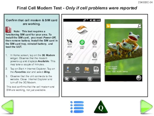
Confirm that cell modem & SIM card are working.
Note: This
Note: This
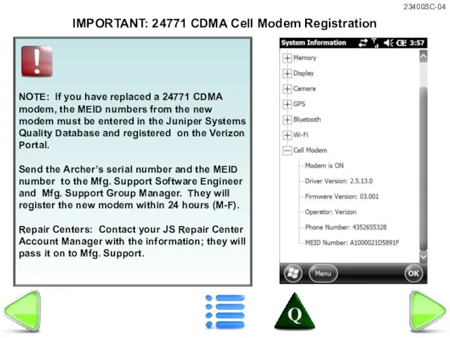
NOTE: If you have replaced a 24771 CDMA modem, the MEID
NOTE: If you have replaced a 24771 CDMA modem, the MEID
Burn new Serial number and run
From the test station computer desktop,
Burn new Serial number and run
From the test station computer desktop,
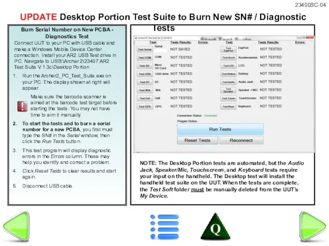
Burn Serial Number on New PCBA -
Diagnostics Test
Connect UUT to your
Burn Serial Number on New PCBA -
Diagnostics Test
Connect UUT to your
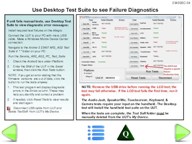
If unit fails manual tests, use Desktop Test Suite to view
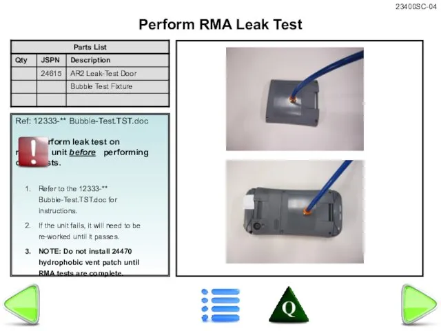
Ref: 12333-** Bubble-Test.TST.doc
Perform leak test on repaired unit before performing other
Ref: 12333-** Bubble-Test.TST.doc
Perform leak test on repaired unit before performing other

Verify product label is correct. Install new label as needed.
Verify product label is correct. Install new label as needed.
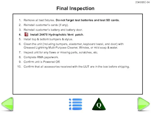
Final Inspection
Remove all test fixtures. Do not forget test batteries and
Final Inspection
Remove all test fixtures. Do not forget test batteries and
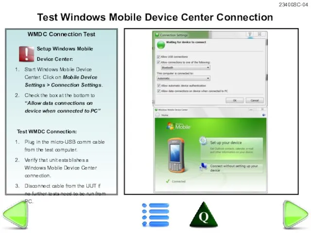
WMDC Connection Test
Setup Windows Mobile
Device Center:
Start Windows Mobile
WMDC Connection Test
Setup Windows Mobile
Device Center:
Start Windows Mobile
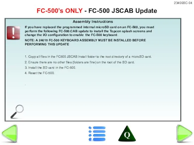
Assembly Instructions
1. Copy all files in the FC500 JSCAB Install folder
Assembly Instructions
1. Copy all files in the FC500 JSCAB Install folder
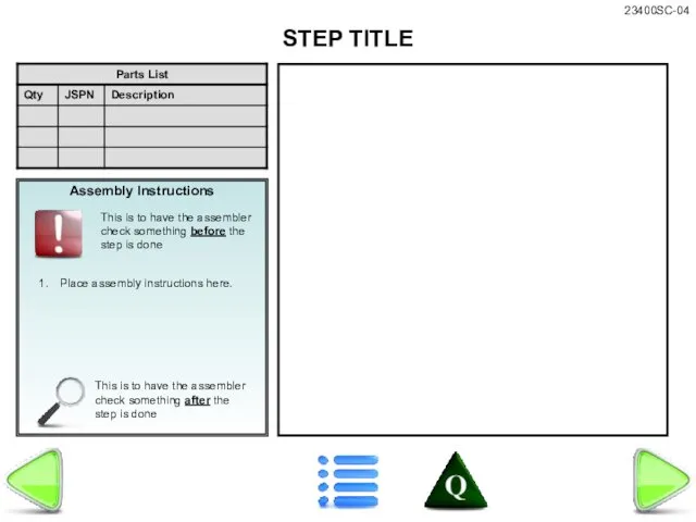
Assembly Instructions
This is to have the assembler check something after the
Assembly Instructions
This is to have the assembler check something after the

Assembly Instructions
This is to have the assembler check something after the
Assembly Instructions
This is to have the assembler check something after the

Assembly Instructions
This is to have the assembler check something after the
Assembly Instructions
This is to have the assembler check something after the
 Знакомьтесь, наш новый сотрудник
 20131110_prezentatsiya22
 Литье в песчаные формы
 Система зажигания
 Архитектор
 Modern mobile phones addiction: reasons and consequences
 Исследовательская работа. Роботы в нашей жизни
 Наша история любви
 Максималды ток қорғанысы
 Православные праздники
 Экспресс-доставка грузов по России
 Учителя первых классов на 2015-2016 учебный год
 Дорожная карта
 Опасная ловушка
 Взвейтесь кострами
 Технологическая документация для изготовления изделий на станках
 ЗиОБЖ_Режим питания. Ужин. Обобщение
 Red Hot Chili Peppers
 Рекомендации по подбору индивидуального стиля
 Параллельное соединение элементов в цепи синусоидального тока
 Македония - 2015
 Моя школа вчера, сегодня, завтра
 Металургія сталі. Виробництво сталі в мартенівських печах
 Основы литейного производства
 Сюжетно-ролевая игра Путешествие на самолете группа Звездочка
 20120427_urok_muzyki_3_klass
 Поиск по картинке вариант 3 (3)_0_1649428572
 Упрощение выражений (подготовка к к/р)