- Installation and startup. Immersive technologies

Содержание
- 2. INSTALLATION & STARTUP / CONTENTS Before starting ………………………………………. Unpacking the HESTIA VR pod ……………………. Installing the
- 3. Before starting, please read this manual. Dear customer, The product you have purchased was manufactured in
- 4. Unpacking the HESTIA VR pod THE IMMERSIVE SOLUTION HUB
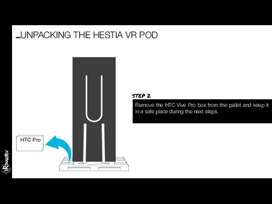
- 5. The pods are delivered on EU pallets. The package measures (in cm): 100 (l) x 80
- 6. Remove the HTC Vive Pro box from the pallet and keep it in a safe place
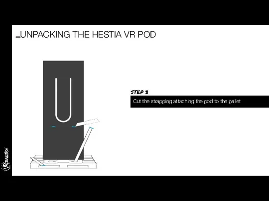
- 7. Cut the strapping attaching the pod to the pallet UNPACKING THE HESTIA VR POD STEP 3
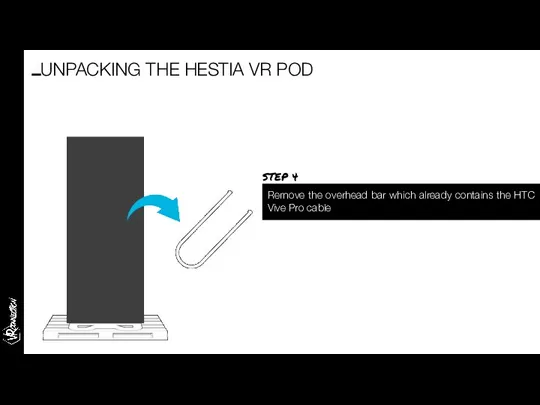
- 8. Remove the overhead bar which already contains the HTC Vive Pro cable UNPACKING THE HESTIA VR
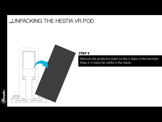
- 9. Remove the protective foam on the 4 sides of the terminal. Keep it, it many be
- 10. With the help of a second person, remove the pod from the pallet and place it
- 11. Fit the overhead bar onto the top of the pod in the holes provided for this
- 12. Open the HTC Vive box which was on the pallet and take out the headset, controllers
- 13. Plug the cable extending from of the overhead bar into the HTC Vive PRO. Then press
- 14. Open out the bracket on the left-hand side of the pod. You can now hang the
- 15. Plug the controller cables into the holes provided under the touchscreen. Connect the controllers to these
- 16. Installing the QR reader THE IMMERSIVE SOLUTION HUB
- 17. To install the QR reader, go to the door of the HESTIA VR pod. Slide the
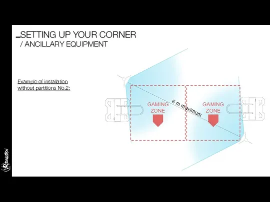
- 18. Setting up your corner: ancillary equipment THE IMMERSIVE SOLUTION HUB
- 19. Pod wiring diagram The connections required by your Hestia VR pod Spectator screen with HDMI connection
- 20. All the pods must be connected via an RJ45 connection to the router supplied by VRC,
- 21. Whether on stands or attached to the wall, the sensors must be placed diagonally in relation
- 22. Example of installation without partitions No.2: GAMING ZONE GAMING ZONE 6 m maximum SETTING UP YOUR
- 23. Startup THE IMMERSIVE SOLUTION HUB
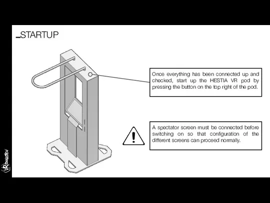
- 24. Once everything has been connected up and checked, start up the HESTIA VR pod by pressing
- 25. Once the pod is switched on, several services will launch in the background. The VRC launcher
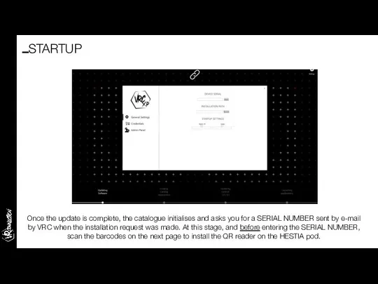
- 26. Once the update is complete, the catalogue initialises and asks you for a SERIAL NUMBER sent
- 27. STARTUP Scan the “Set factory Defaults” barcode with the QR reader laser to initialise it: Then
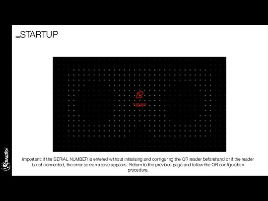
- 28. Important: if the SERIAL NUMBER is entered without initialising and configuring the QR reader beforehand or
- 29. Then enter the SERIAL NUMBER by connecting a keyboard to one of the available USB ports
- 30. The SERIAL NUMBER is valid. Installation can continue. STARTUP
- 31. The VRC launcher then downloads the experiences which will be presented in the catalogue. STARTUP
- 32. Once the downloads are complete, the catalogue launches and is ready to use. STARTUP
- 33. Configuring the QR printer
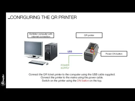
- 34. USB POWER SUPPLY Connect the QR ticket printer to the computer using the USB cable supplied.
- 35. To install the QR ticket printer on your computer, go to the VRC XP Lite website:
- 36. Your browser opens and warns you of an unsecured connection. Select “know more” in order to
- 37. Your browser asks you if you want to add a security exception for this website. Click
- 38. Your browser informs you that the certificate has been accepted: A pop-up then asks you if
- 39. In the task bar, right-click on the “Zebra Printer” program and select “Settings” (image below). The
- 40. Go to the VRC XP Lite website, “QR ticket” page, “Print” tab (see “Functional test” slides)
- 41. Functional test THE IMMERSIVE SOLUTION HUB
- 42. Using the exhibitor computer, go onto the https://lite.vrcxp.com/ website and log in using the exhibitor’s username
- 43. Go to the “QR Code” page, “Print” tab and print a ticket of one of the
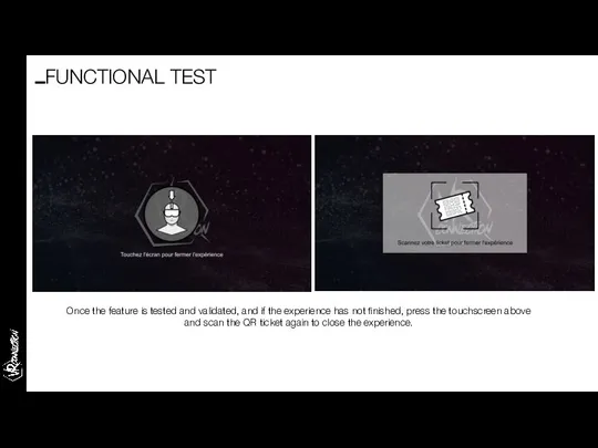
- 44. Return to the pod, select an experience corresponding to the type of ticket printed and scan
- 45. In order to use the HTC VIVE headset properly, the gaming area first needs to be
- 46. Once the feature is tested and validated, and if the experience has not finished, press the
- 47. System troubleshooting guide THE IMMERSIVE SOLUTION HUB
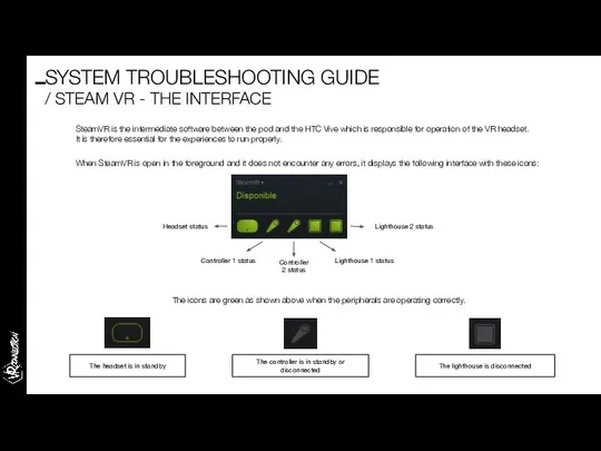
- 48. SteamVR is the intermediate software between the pod and the HTC Vive which is responsible for
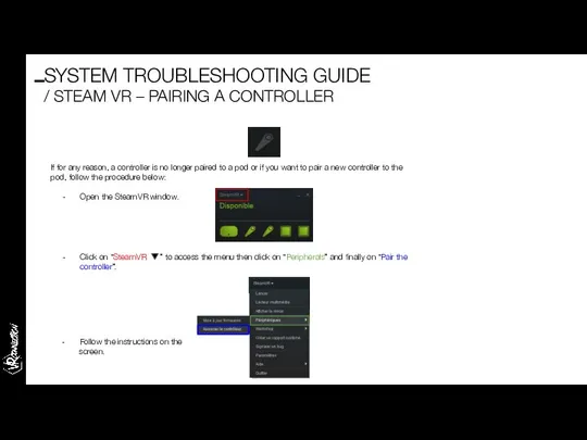
- 49. If for any reason, a controller is no longer paired to a pod or if you
- 50. The controller has already been paired but seems to be on standby or disconnected: When SteamVR
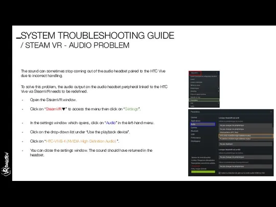
- 51. SYSTEM TROUBLESHOOTING GUIDE / STEAM VR - AUDIO PROBLEM The sound can sometimes stop coming out
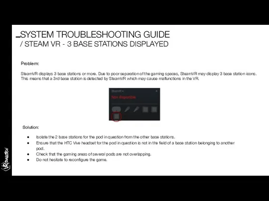
- 52. Problem: SteamVR displays 3 base stations or more. Due to poor separation of the gaming spaces,
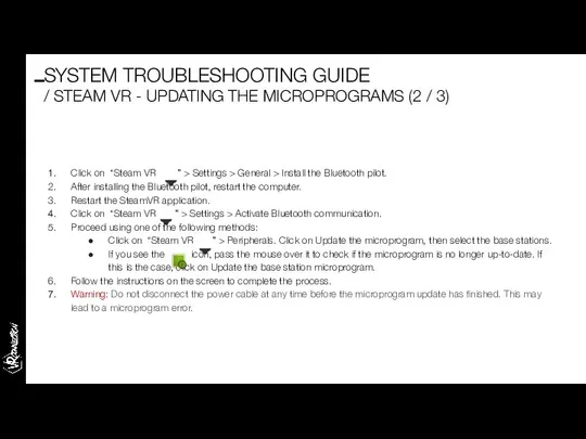
- 53. If you see the icon, pass the mouse over it to check if the microprogram is
- 54. Click on “Steam VR ” > Settings > General > Install the Bluetooth pilot. After installing
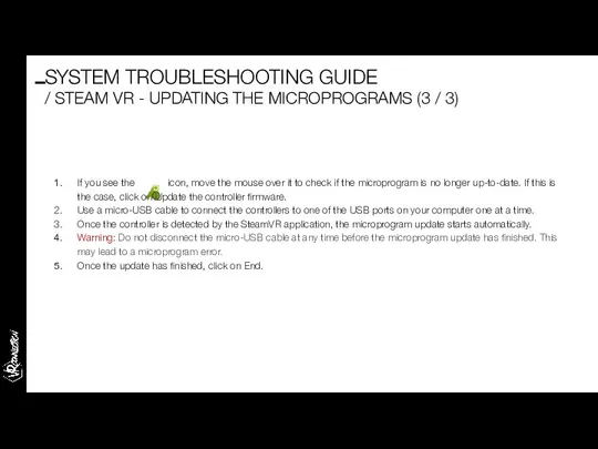
- 55. If you see the icon, move the mouse over it to check if the microprogram is
- 57. After-Sales process THE IMMERSIVE SOLUTION HUB
- 58. Before starting, please refer to the maintenance contract. The maintenance process is defined on 3 levels:
- 59. The VRC online guide is a website grouping all the documentation necessary for installation, operation and
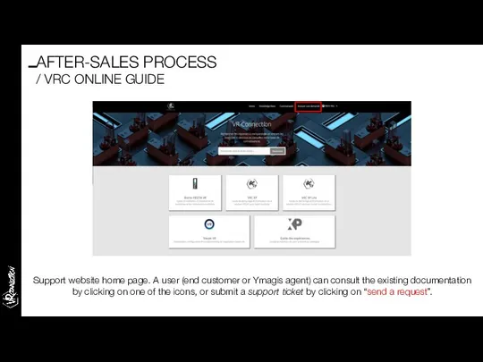
- 60. Support website home page. A user (end customer or Ymagis agent) can consult the existing documentation
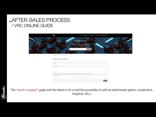
- 61. The “send a request” page with the fields to fill in and the possibility to add
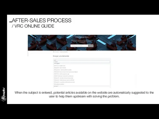
- 62. When the subject is entered, potential articles available on the website are automatically suggested to the
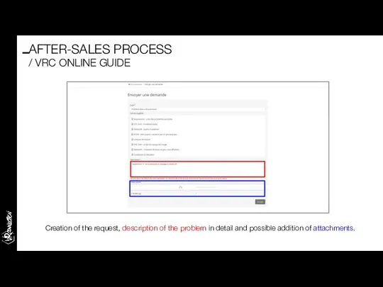
- 63. Creation of the request, description of the problem in detail and possible addition of attachments. AFTER-SALES
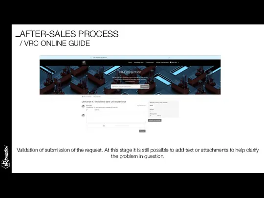
- 64. Validation of submission of the request. At this stage it is still possible to add text
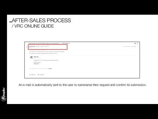
- 65. An e-mail is automatically sent to the user to summarise their request and confirm its submission.
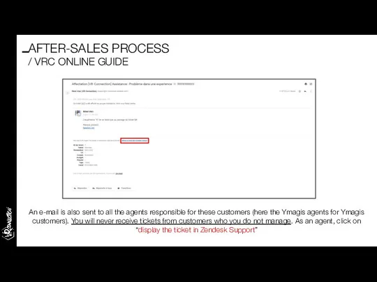
- 66. An e-mail is also sent to all the agents responsible for these customers (here the Ymagis
- 67. By clicking on the link mentioned in the previous slide as an agent, you come to
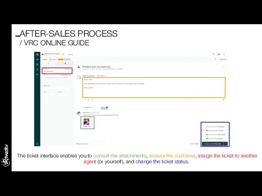
- 68. The ticket interface enables you to consult the attachments, answer the customer, assign the ticket to
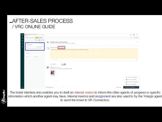
- 69. The ticket interface also enables you to draft an internal memo to inform the other agents
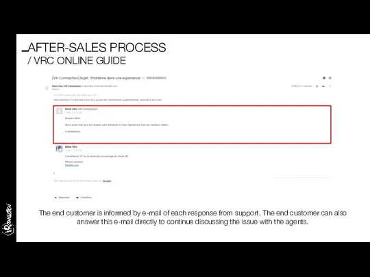
- 70. The end customer is informed by e-mail of each response from support. The end customer can
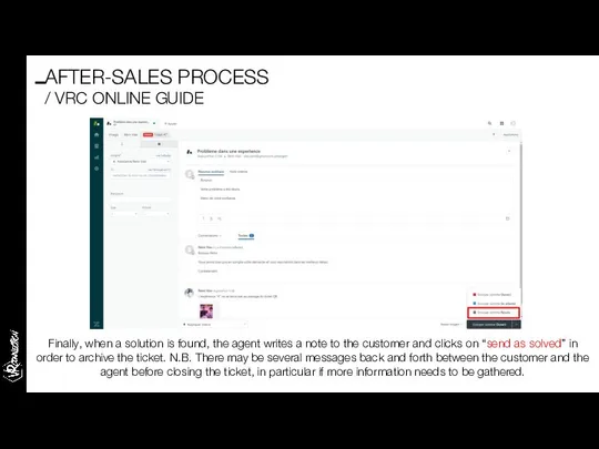
- 71. Finally, when a solution is found, the agent writes a note to the customer and clicks
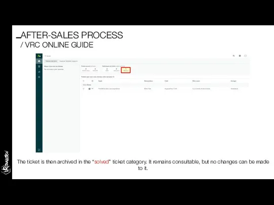
- 72. The ticket is then archived in the “solved” ticket category. It remains consultable, but no changes
- 74. Скачать презентацию
INSTALLATION & STARTUP
/ CONTENTS
Before starting ……………………………………….
Unpacking the HESTIA VR pod …………………….
Installing
INSTALLATION & STARTUP
/ CONTENTS
Before starting ……………………………………….
Unpacking the HESTIA VR pod …………………….
Installing
Before starting,
please read this manual.
Dear customer,
The product you have purchased was
Before starting,
please read this manual.
Dear customer,
The product you have purchased was
Unpacking the
HESTIA VR pod
THE IMMERSIVE SOLUTION HUB
Unpacking the
HESTIA VR pod
THE IMMERSIVE SOLUTION HUB
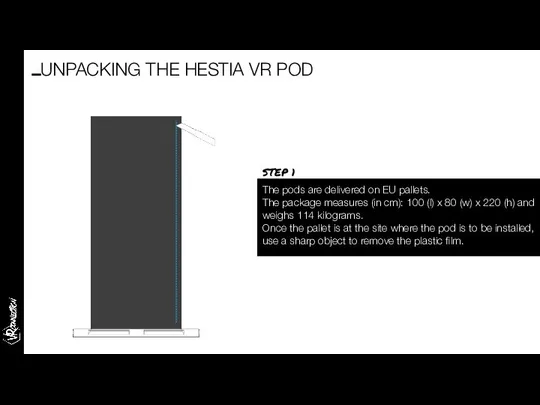
The pods are delivered on EU pallets.
The package measures (in
The pods are delivered on EU pallets.
The package measures (in
Remove the HTC Vive Pro box from the pallet and keep
Remove the HTC Vive Pro box from the pallet and keep
Cut the strapping attaching the pod to the pallet
UNPACKING THE HESTIA
Cut the strapping attaching the pod to the pallet
UNPACKING THE HESTIA
Remove the overhead bar which already contains the HTC Vive Pro
Remove the overhead bar which already contains the HTC Vive Pro
Remove the protective foam on the 4 sides of the terminal.
Remove the protective foam on the 4 sides of the terminal.
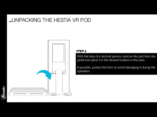
With the help of a second person, remove the pod from
With the help of a second person, remove the pod from
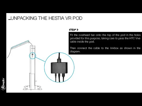
Fit the overhead bar onto the top of the pod in
Fit the overhead bar onto the top of the pod in
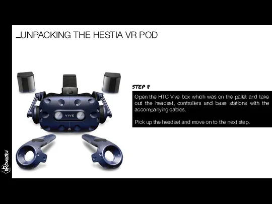
Open the HTC Vive box which was on the pallet and
Open the HTC Vive box which was on the pallet and
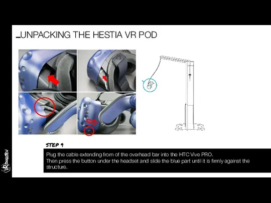
Plug the cable extending from of the overhead bar into the
Plug the cable extending from of the overhead bar into the
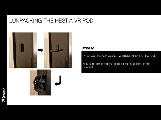
Open out the bracket on the left-hand side of the pod.
You
Open out the bracket on the left-hand side of the pod.
You
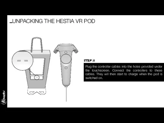
Plug the controller cables into the holes provided under the touchscreen.
Plug the controller cables into the holes provided under the touchscreen.
Installing the QR reader
THE IMMERSIVE SOLUTION HUB
Installing the QR reader
THE IMMERSIVE SOLUTION HUB
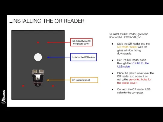
To install the QR reader, go to the door of the
To install the QR reader, go to the door of the
Setting up your corner:
ancillary equipment
THE IMMERSIVE SOLUTION HUB
Setting up your corner:
ancillary equipment
THE IMMERSIVE SOLUTION HUB
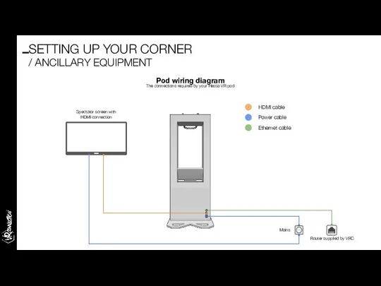
Pod wiring diagram
The connections required by your Hestia VR pod
Spectator screen
Pod wiring diagram
The connections required by your Hestia VR pod
Spectator screen
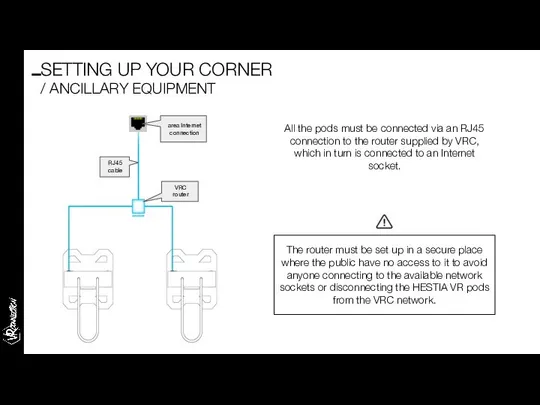
All the pods must be connected via an RJ45 connection to
All the pods must be connected via an RJ45 connection to
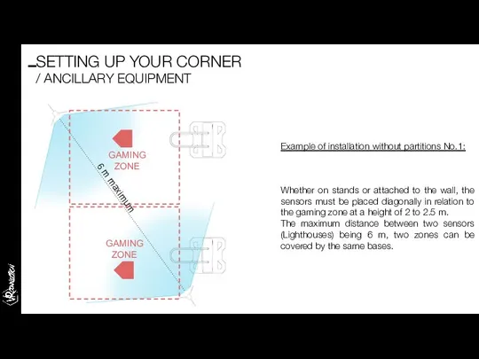
Whether on stands or attached to the wall, the sensors must
Whether on stands or attached to the wall, the sensors must
Example of installation
without partitions No.2:
GAMING ZONE
GAMING ZONE
6 m maximum
SETTING UP
Example of installation
without partitions No.2:
GAMING ZONE
GAMING ZONE
6 m maximum
SETTING UP

Startup
THE IMMERSIVE SOLUTION HUB
Startup
THE IMMERSIVE SOLUTION HUB
Once everything has been connected up and checked, start up the
Once everything has been connected up and checked, start up the

Once the pod is switched on, several services will launch in
Once the pod is switched on, several services will launch in
Once the update is complete, the catalogue initialises and asks you
Once the update is complete, the catalogue initialises and asks you

STARTUP
Scan the “Set factory Defaults” barcode with the QR reader laser
STARTUP
Scan the “Set factory Defaults” barcode with the QR reader laser
Important: if the SERIAL NUMBER is entered without initialising and configuring
Important: if the SERIAL NUMBER is entered without initialising and configuring
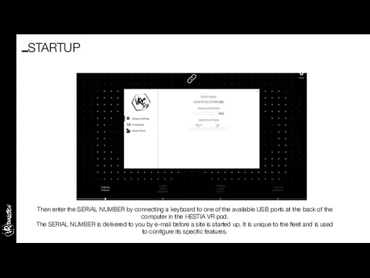
Then enter the SERIAL NUMBER by connecting a keyboard to one
Then enter the SERIAL NUMBER by connecting a keyboard to one
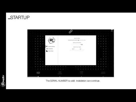
The SERIAL NUMBER is valid. Installation can continue.
STARTUP
The SERIAL NUMBER is valid. Installation can continue.
STARTUP

The VRC launcher then downloads the experiences which will be presented
The VRC launcher then downloads the experiences which will be presented
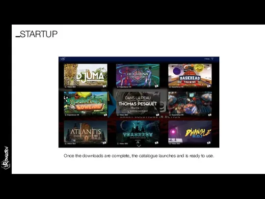
Once the downloads are complete, the catalogue launches and is ready
Once the downloads are complete, the catalogue launches and is ready
Configuring the QR printer
Configuring the QR printer
USB
POWER SUPPLY
Connect the QR ticket printer to the computer using the
USB
POWER SUPPLY
Connect the QR ticket printer to the computer using the
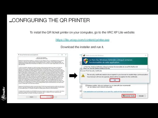
To install the QR ticket printer on your computer, go to
To install the QR ticket printer on your computer, go to
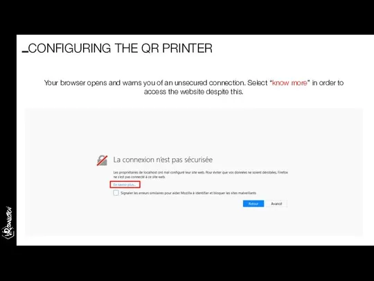
Your browser opens and warns you of an unsecured connection. Select
Your browser opens and warns you of an unsecured connection. Select
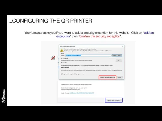
Your browser asks you if you want to add a security
Your browser asks you if you want to add a security
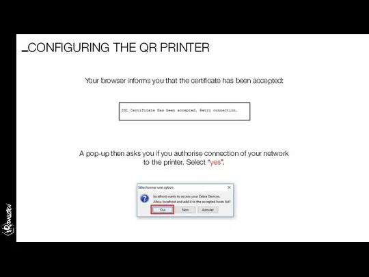
Your browser informs you that the certificate has been accepted:
A pop-up
Your browser informs you that the certificate has been accepted:
A pop-up
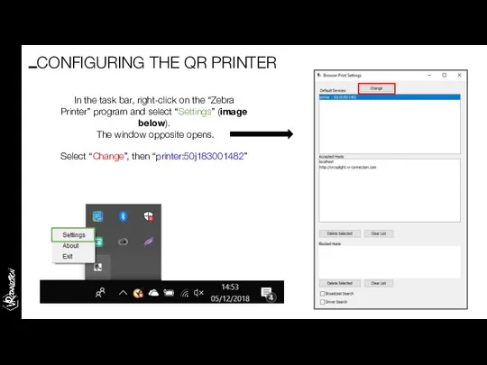
In the task bar, right-click on the “Zebra Printer” program and
In the task bar, right-click on the “Zebra Printer” program and
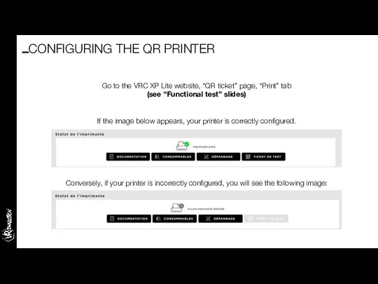
Go to the VRC XP Lite website, “QR ticket” page, “Print”
Go to the VRC XP Lite website, “QR ticket” page, “Print”
Functional test
THE IMMERSIVE SOLUTION HUB
Functional test
THE IMMERSIVE SOLUTION HUB
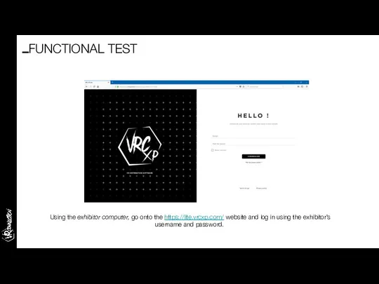
Using the exhibitor computer, go onto the https://lite.vrcxp.com/ website and log
Using the exhibitor computer, go onto the https://lite.vrcxp.com/ website and log
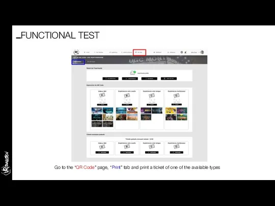
Go to the “QR Code” page, “Print” tab and print a
Go to the “QR Code” page, “Print” tab and print a
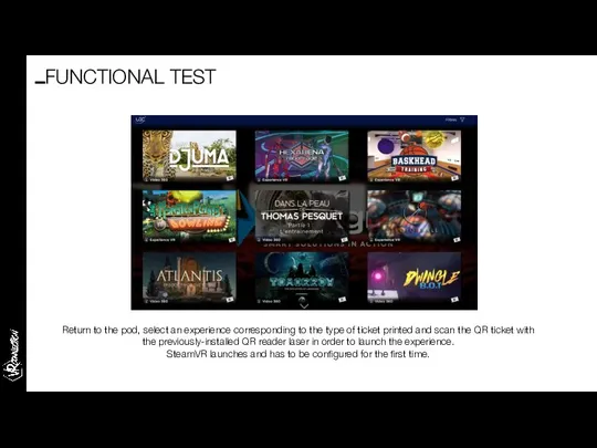
Return to the pod, select an experience corresponding to the type
Return to the pod, select an experience corresponding to the type
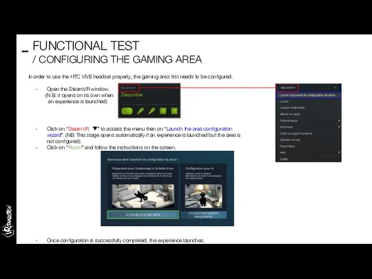
In order to use the HTC VIVE headset properly, the gaming
In order to use the HTC VIVE headset properly, the gaming
Once the feature is tested and validated, and if the experience
Once the feature is tested and validated, and if the experience
System troubleshooting guide
THE IMMERSIVE SOLUTION HUB
System troubleshooting guide
THE IMMERSIVE SOLUTION HUB
SteamVR is the intermediate software between the pod and the HTC
SteamVR is the intermediate software between the pod and the HTC
If for any reason, a controller is no longer paired to
If for any reason, a controller is no longer paired to
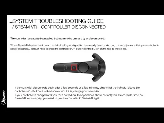
The controller has already been paired but seems to be on
The controller has already been paired but seems to be on
SYSTEM TROUBLESHOOTING GUIDE
/ STEAM VR - AUDIO PROBLEM
The sound can sometimes
SYSTEM TROUBLESHOOTING GUIDE
/ STEAM VR - AUDIO PROBLEM
The sound can sometimes
Problem:
SteamVR displays 3 base stations or more. Due to poor
Problem:
SteamVR displays 3 base stations or more. Due to poor
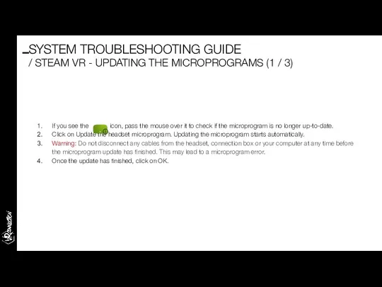
If you see the icon, pass the mouse over it to
If you see the icon, pass the mouse over it to
Click on “Steam VR ” > Settings > General > Install
Click on “Steam VR ” > Settings > General > Install
If you see the icon, move the mouse over it to
If you see the icon, move the mouse over it to
After-Sales process
THE IMMERSIVE SOLUTION HUB
After-Sales process
THE IMMERSIVE SOLUTION HUB
Before starting,
please refer to the maintenance contract.
The maintenance process is defined
Before starting,
please refer to the maintenance contract.
The maintenance process is defined
The VRC online guide is a website grouping all the documentation
Support website home page. A user (end customer or Ymagis agent)
Support website home page. A user (end customer or Ymagis agent)
The “send a request” page with the fields to fill in
The “send a request” page with the fields to fill in
When the subject is entered, potential articles available on the website
When the subject is entered, potential articles available on the website
Creation of the request, description of the problem in detail and
Creation of the request, description of the problem in detail and
Validation of submission of the request. At this stage it is
Validation of submission of the request. At this stage it is
An e-mail is automatically sent to the user to summarise their
An e-mail is automatically sent to the user to summarise their
An e-mail is also sent to all the agents responsible for
An e-mail is also sent to all the agents responsible for

By clicking on the link mentioned in the previous slide as
By clicking on the link mentioned in the previous slide as
The ticket interface enables you to consult the attachments, answer the
The ticket interface enables you to consult the attachments, answer the
The ticket interface also enables you to draft an internal memo
The ticket interface also enables you to draft an internal memo
The end customer is informed by e-mail of each response from
The end customer is informed by e-mail of each response from
Finally, when a solution is found, the agent writes a note
Finally, when a solution is found, the agent writes a note
The ticket is then archived in the “solved” ticket category. It
The ticket is then archived in the “solved” ticket category. It
 Экскурсионная программа для школьников. Парк «Ключи»
 15 минут про космическое право
 Обществознание. Довузовская подготовка (2)
 Загальні відомості і принципи дії фідерних пристроїв (Заняття №4.1)
 Тема : «Логические задачи»
 Влияние деятельности правоохранительных органов на степень соответствия статистических данных реальной преступности
 обробка безлускатої риби
 Презентация "Изобразительное искусство" - скачать презентации по МХК
 Выполнила: ученица 8 «В» Ермакова Лиза
  Парики. Виды париков
 Дом, в котором уютно всем
 Customs and traditions in Britain
 Футбол. Изменения в правилах игры
 Как оспорить предупреждение, предписание и решение госоргана
 Механические и технологические испытания: испытания на кручение и на срез, на длительную прочность и ползучесть
 Травмы магистральных сосудов
 ОСВ-1. Принципы, параметры, значение
 Алгебра логики на практике
 Поведенческие аспекты контроля
 Бизнес – проект по развитию садоводства
 Преподавание французского языка в МБОУСОШ № 8
 Введение в доисторическое артефакты и визуальная культура синтоизма
 Кожаные куртки
 Выполнение сборочного чертежа
 Организация учебного проекта и этапы его проведения. Работа составлена Доржу Байлак Салчаковной, учителем математики МООУ СШИ
 Презентация ГОСУДАРСТВО
 Презентация на тему "Специальные предметные умения школьников 1-4-х классов по математике: их развитие и диагностика" - скачать
 Вопросы по архитектуре