- Drilling Engineering

Содержание
- 2. Circulating System
- 3. For incompressible fluids, the specific weight of the liquid in field unit is given by If
- 4. Example: Calculate the static mud density required to prevent flow from a permeable stratum at 12,200ft
- 5. EOS of gas: Hydrostatic Pressure in Gas Column
- 6. A well contains tubing filled with methane gas (MW = 16) to a vertical depth of
- 7. The pressure in the annulus (external pressure) at D = 10,000 ft is P2 = 0.052
- 8. Hydrostatic Pressure in Complex Fluid Column
- 9. Hydrostatic Pressure in Complex Fluid Column
- 10. The effective density exerted by a circulating fluid against the formation that takes into account the
- 11. Example: A 9.5-PPG drilling fluid is circulated through the drill pipe and the annulus. The frictional
- 12. Buoyancy We , W, Wbo – effective weight, weight of the object in air, and buoyant
- 13. 10,000 ft of 19.5-lbm/ft drillpipe and 600 ft of 147 lbm/ft drill collars are suspended off
- 14. Energy balance: ΔPp is heat entering the system ΔPf is heat loss due to friction Flow
- 15. Applying the energy equation for a flow through a nozzle with neglecting: effects of elevation: D2
- 16. Flow Through Jet Bits
- 17. Assuming a constant ΔPb through all the nozzles Pressure drop across the bit ρ – lbm/gal
- 18. The purpose of the jet nozzles is to improve the cleaning action of the drilling fluid
- 19. Example: A 12.0 lbm/gal drilling fluid is flowing through a bit containing three 13/32 in nozzles
- 20. Rheological Model Newtonian fluids: Power law fluids: Bingham fluids: Herschel-Bulkley (Yield power law fluids)
- 21. Newtonian Model Non-Newtonian Model Bingham-plastic model Power Law model: Yield power law model: Rheological Model
- 22. Pseudoplastic (Time-independent shear thinning fluids) If the apparent viscosity decreases with increasing shear rate Dilatant (Time-independent
- 23. Thixotropic (Time-dependent shear thinning fluids): If the apparent viscosity decreases with time after the shear rate
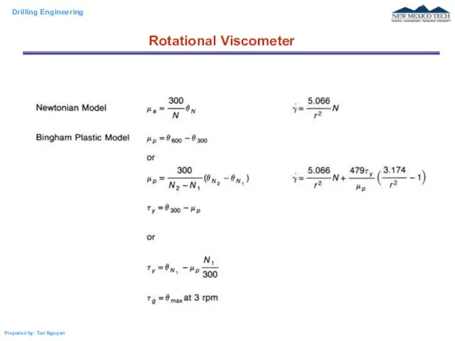
- 24. Rotational Viscometer
- 25. A rotational viscometer is used to determine type of the fluid and the rheological model of
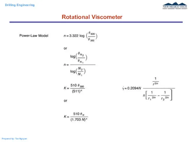
- 26. Rotational Viscometer
- 27. Rotational Viscometer
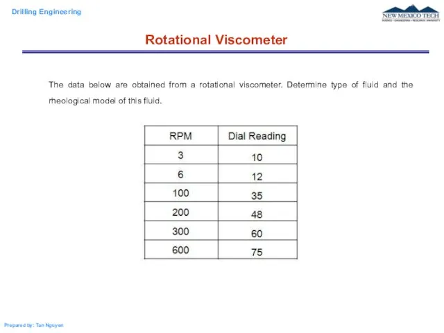
- 28. Rotational Viscometer The data below are obtained from a rotational viscometer. Determine type of fluid and
- 30. Скачать презентацию
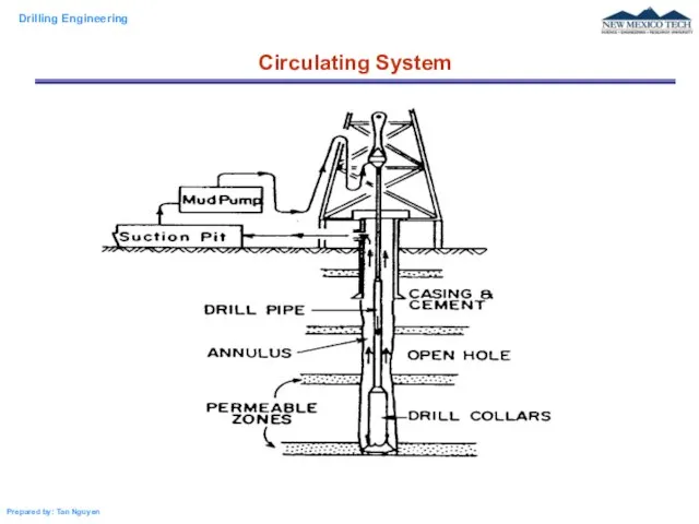
Circulating System
Circulating System
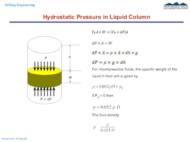
For incompressible fluids, the specific weight of the liquid in field
For incompressible fluids, the specific weight of the liquid in field
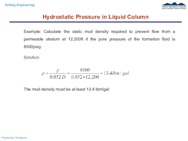
Example: Calculate the static mud density required to prevent flow from
Example: Calculate the static mud density required to prevent flow from
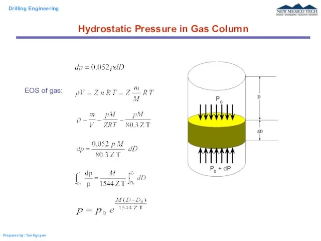
EOS of gas:
Hydrostatic Pressure in Gas Column
Hydrostatic Pressure in Gas Column
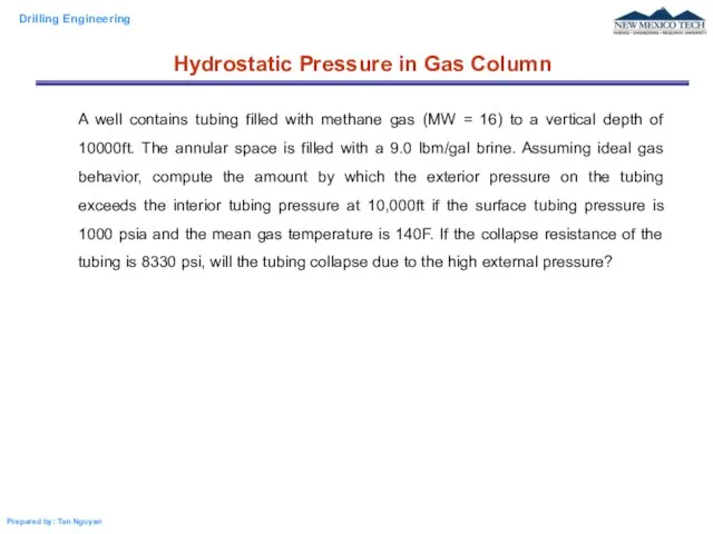
A well contains tubing filled with methane gas (MW = 16)
A well contains tubing filled with methane gas (MW = 16)
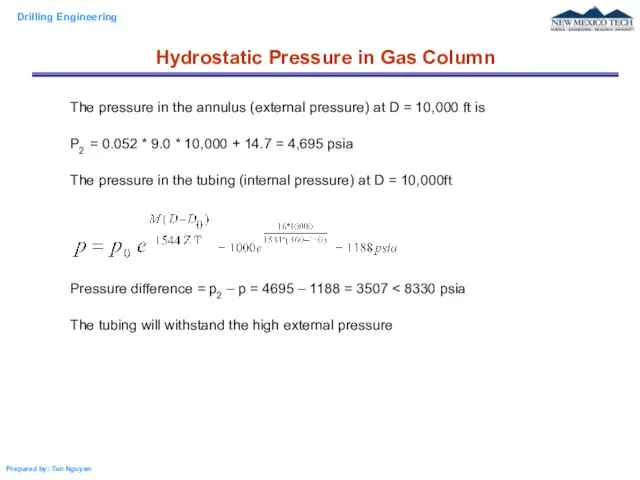
The pressure in the annulus (external pressure) at D = 10,000
The pressure in the annulus (external pressure) at D = 10,000
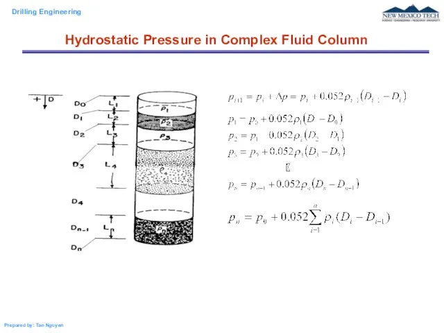
Hydrostatic Pressure in Complex Fluid Column
Hydrostatic Pressure in Complex Fluid Column
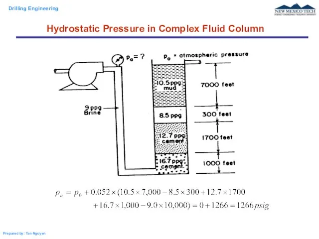
Hydrostatic Pressure in Complex Fluid Column
Hydrostatic Pressure in Complex Fluid Column
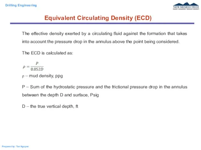
The effective density exerted by a circulating fluid against the formation
The effective density exerted by a circulating fluid against the formation
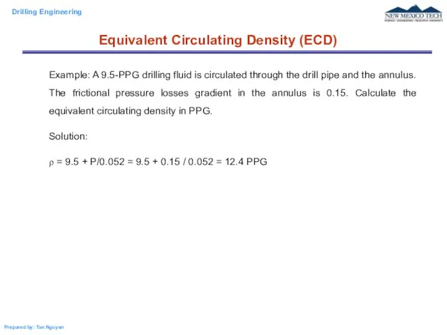
Example: A 9.5-PPG drilling fluid is circulated through the drill pipe
Example: A 9.5-PPG drilling fluid is circulated through the drill pipe
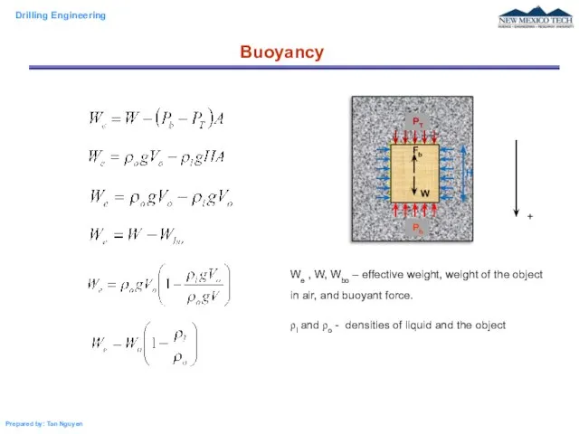
Buoyancy
We , W, Wbo – effective weight, weight of the object
Buoyancy
We , W, Wbo – effective weight, weight of the object
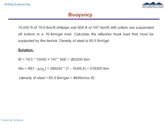
10,000 ft of 19.5-lbm/ft drillpipe and 600 ft of 147 lbm/ft
10,000 ft of 19.5-lbm/ft drillpipe and 600 ft of 147 lbm/ft
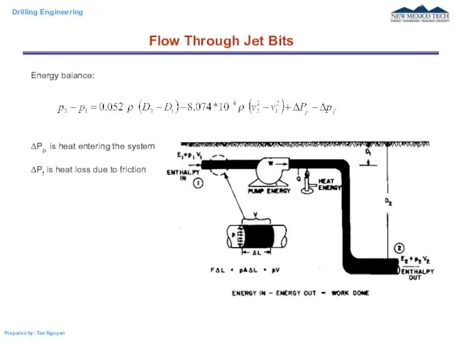
Energy balance:
ΔPp is heat entering the system
ΔPf is heat loss due
Energy balance:
ΔPp is heat entering the system
ΔPf is heat loss due
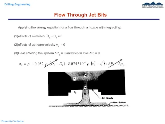
Applying the energy equation for a flow through a nozzle with
Applying the energy equation for a flow through a nozzle with
Flow Through Jet Bits
Flow Through Jet Bits
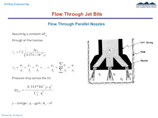
Assuming a constant ΔPb
through all the nozzles
Pressure drop across
Assuming a constant ΔPb
through all the nozzles
Pressure drop across
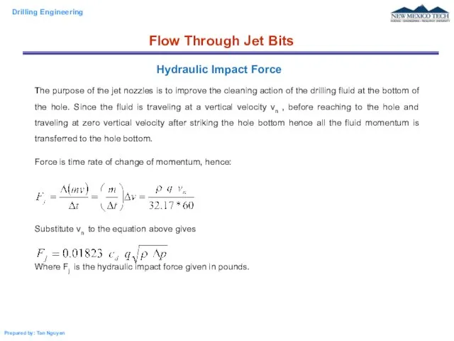
The purpose of the jet nozzles is to improve the cleaning
The purpose of the jet nozzles is to improve the cleaning
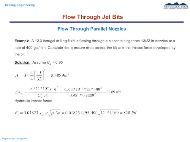
Example: A 12.0 lbm/gal drilling fluid is flowing through a bit
Example: A 12.0 lbm/gal drilling fluid is flowing through a bit
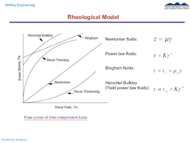
Rheological Model
Newtonian fluids:
Power law fluids:
Bingham fluids:
Herschel-Bulkley
(Yield power law fluids)
Rheological Model
Newtonian fluids:
Power law fluids:
Bingham fluids:
Herschel-Bulkley
(Yield power law fluids)
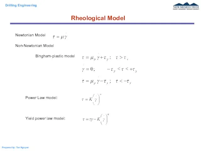
Newtonian Model
Non-Newtonian Model
Bingham-plastic model
Power Law model:
Yield power law model:
Rheological Model
Newtonian Model
Non-Newtonian Model
Bingham-plastic model
Power Law model:
Yield power law model:
Rheological Model
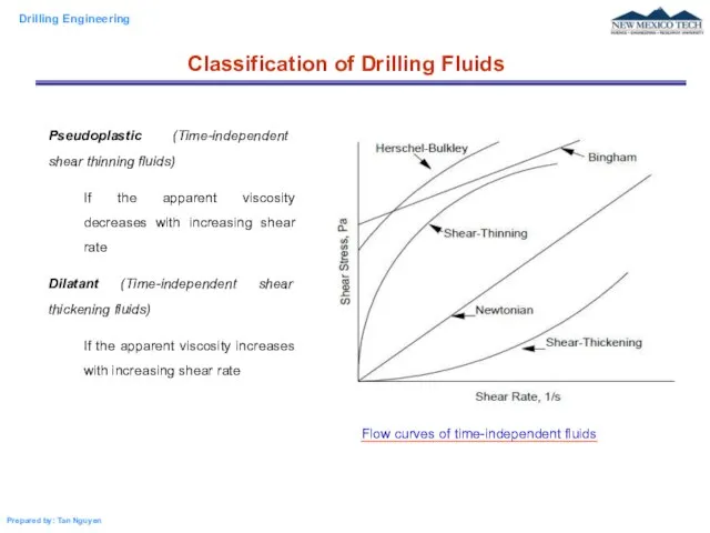
Pseudoplastic (Time-independent shear thinning fluids)
If the apparent viscosity decreases with increasing
Pseudoplastic (Time-independent shear thinning fluids)
If the apparent viscosity decreases with increasing
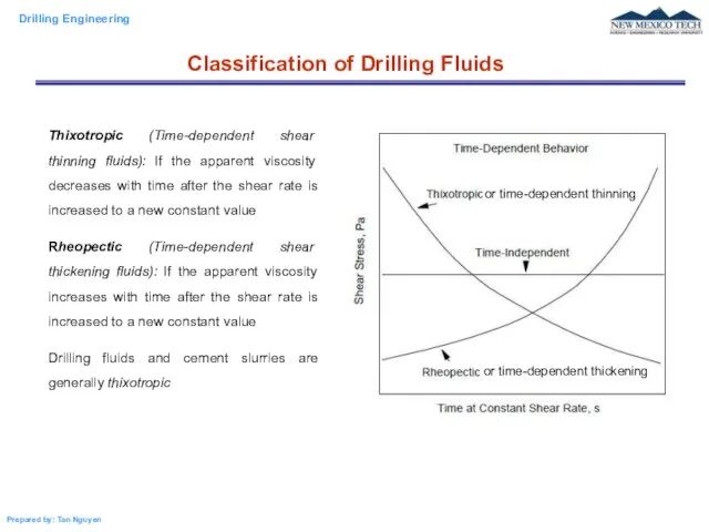
Thixotropic (Time-dependent shear thinning fluids): If the apparent viscosity decreases with
Thixotropic (Time-dependent shear thinning fluids): If the apparent viscosity decreases with
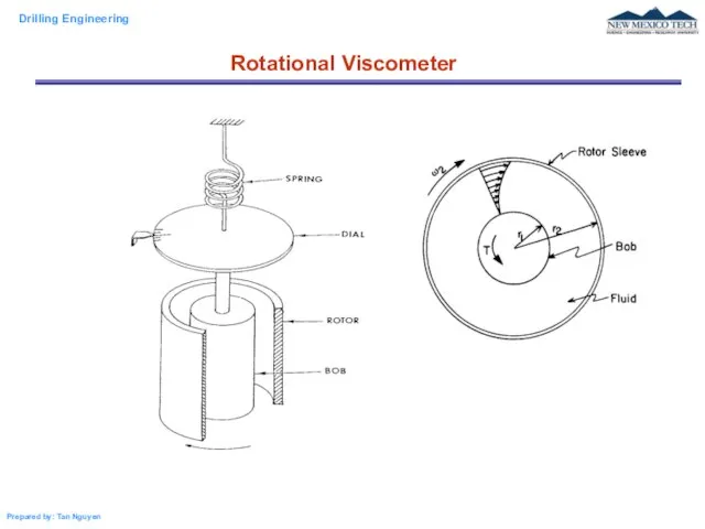
Rotational Viscometer
Rotational Viscometer
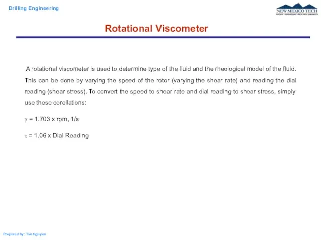
A rotational viscometer is used to determine type of the
A rotational viscometer is used to determine type of the
Rotational Viscometer
Rotational Viscometer
Rotational Viscometer
Rotational Viscometer
Rotational Viscometer
The data below are obtained from a rotational viscometer.
Rotational Viscometer
The data below are obtained from a rotational viscometer.
 Казанский университет. Институт физики
 Деформация - изменение формы или размеров тел под действием внешних сил
 Енергія електричного поля
 Полупроводниковые приборы
 Понятие термодинамики
 Проводники в электростатическом поле
 Тема: Простые механизмы. Работа ученика 7 «в» СОШ №7 г.Якутска Филиппова Юры Руководитель проекта А.П.Филиппова
 Теплота парообразования. Сжижение газов. Влажность воздуха
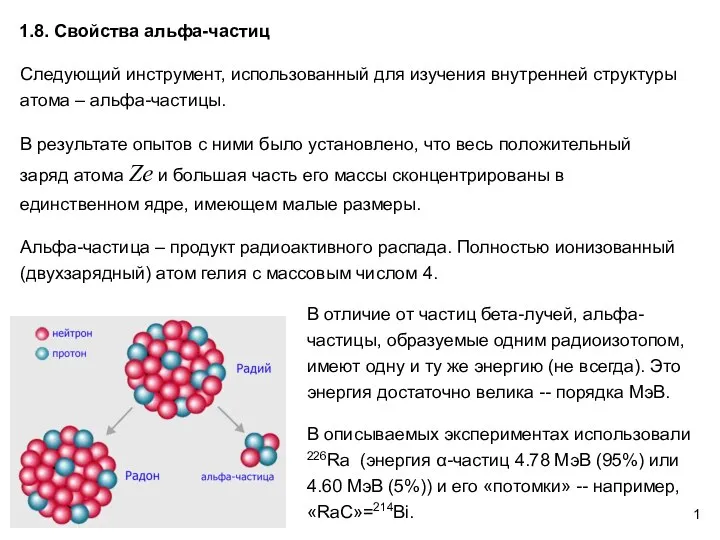 Свойства альфа-частиц. АФ1.8
 Нейтрон и его свойства
 מתקני הרמה ושינוע הרצאה :מתקני הרמה. כבלים ,חבלים ,שרשרות
 Команда «По» представляет: Закон сохранения импульса. Реактивное движение
 Электростатика. Электрический заряд
 Электрическое поле. Законы постоянного тока
 Проект по физике на тему: «Экология, энергетика, человек»
 Модель атома Резерфорда Ядерная или Планетарная модель атома Вонс Диана и Тарамова Айза 10«Б»
  Лазер. История создания лазера. Устройство лазера. Применение лазера
 Система и окружающая среда
 Контактные явления
 Неньютоновские жидкости
 Дипломный проект. Ремонт, мотаж и эксплуатация домкратов
 Вычисления массы и массовой доли растворенного вещества (11 класс)
 Презентация по физике "Радиация и её влияние на окружающую среду" - скачать
  Теплообмен излучением между телами, разделённой прозрачной средой. Коэффициент облучённости. Теплообмен между телами
 Количественный анализ. Хроматографические методы
 Тепловые процессы. Теплообменники. Нагрев острым паром
 Презентация по физике Электромагнитная индукция. Опыты Фарадея Подготовка к ГИА
  Презентация Законы преломления.