- Mathematical Modeling of Energy Efficiency

Содержание
- 2. Formalized topological methods for the analysis of electrical circuits These methods are based on the use
- 3. The connection point of two or more electrical circuits is called a node or a node
- 4. A node is usually indicated by a dot in a circuit. If a short circuit (a
- 5. A loop is a closed path formed by starting at a node, passing through a set
- 6. The method of connecting branches and nodes of an electrical circuit, that is, a structural diagram
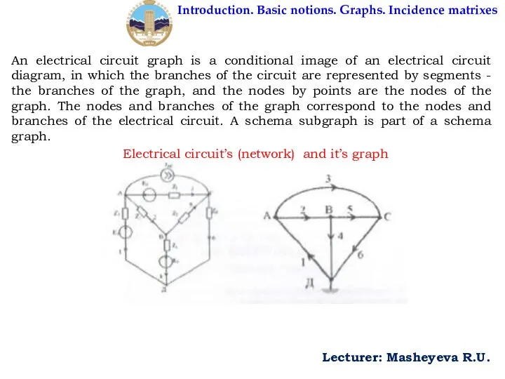
- 7. Introduction. Basic notions. Graphs. Incidence matrixes Lecturer: Masheyeva R.U. An electrical circuit graph is a conditional
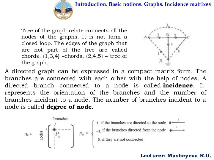
- 8. Introduction. Basic notions. Graphs. Incidence matrixes Lecturer: Masheyeva R.U. Tree of the graph relate connects all
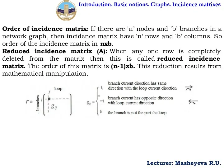
- 9. Introduction. Basic notions. Graphs. Incidence matrixes Lecturer: Masheyeva R.U. Order of incidence matrix: If there are
- 11. Скачать презентацию
Formalized topological methods for the analysis of electrical circuits
These methods are
Formalized topological methods for the analysis of electrical circuits
These methods are
The connection point of two or more electrical circuits is called
The connection point of two or more electrical circuits is called
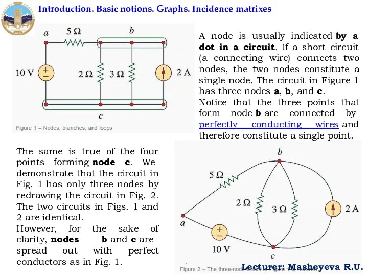
A node is usually indicated by a dot in a circuit. If
A node is usually indicated by a dot in a circuit. If
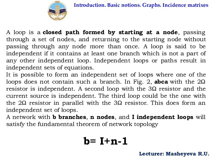
A loop is a closed path formed by starting at a node,
A loop is a closed path formed by starting at a node,
The method of connecting branches and nodes of an electrical circuit,
The method of connecting branches and nodes of an electrical circuit,
Introduction. Basic notions. Graphs. Incidence matrixes
Lecturer: Masheyeva R.U.
An electrical circuit graph
Introduction. Basic notions. Graphs. Incidence matrixes
Lecturer: Masheyeva R.U.
An electrical circuit graph
Introduction. Basic notions. Graphs. Incidence matrixes
Lecturer: Masheyeva R.U.
Tree of the graph
Introduction. Basic notions. Graphs. Incidence matrixes
Lecturer: Masheyeva R.U.
Tree of the graph
Introduction. Basic notions. Graphs. Incidence matrixes
Lecturer: Masheyeva R.U.
Order of incidence matrix: If
Introduction. Basic notions. Graphs. Incidence matrixes
Lecturer: Masheyeva R.U.
Order of incidence matrix: If
 Лекция № 1. Основные понятия и законы электротехники. Классификация электрических цепей
 Физические задачи,приводящие к дифференциальным уравнениям
 Зачем нужны ускорители элементарных частиц
 Развитие понятия функции в 17 веке
 Специальная теория относительности Эйнштейна
 Механічна енергія та її види
 Метод подобия явлений. Числа подобия. Критерии подобия
 Движение и его относительность Ключникова Н.В.
  Динамика. Законы Ньютона. (Лекция 2)
 Электротехника, как отрасль науки и техники
 TES, TEC, KES salīdzinājums un klasifikācija, galvenās prasības
 Презентация по физике "Использование ИКТ на уроках физики" - скачать
  §8. Плоскопараллельное движение твердого тела (плоское)
 Інфразвук. Джерела інфразвуку
 История отечественных космических ядерных установок
 Презентация Плотность вещества Взаимодействие тел
 Закон Кулона. Единица электрического заряда
 Удельная теплота парообразования
 Ракеты. Современная космическая ракета
 Fyzika - Physics - Physik
 Магнитные свойства вещества. Диамагнетики.
 Дифракція світла
  Приводы подвагонных генераторов
 Основы теории процесса сушки зерна
 Умови рівноваги тіла
 НАСЫЩЕННЫЙ И НЕНАСЫЩЕННЫЙ ПАР ВЛАЖНОСТЬ ВОЗДУХА КИПЕНИЕ УРОК МОДЕЛИРОВАНИЯ УМЕНИЙ И НАВЫКОВ УЧИТЕЛЬ ФИЗИКИ ЛЕВЧУК М.В. МАКЕ
 Презентация по физике Основное уравнение молекулярно-кинетической теории идеальных газов. Статистические распределение.
 Научные революции в естествознании и формирование научной картины мира