- Physical Output

Содержание
- 2. Physical Output Make things move by controlling motors with Arduino Servo-motors Rotary actuator that allows for
- 3. Brushed DC Motors Simple devices with two leads connected to brushes (contacts) Control the magnetic field
- 4. Brushless Motors More powerful and efficient for a given size Three phases of driving coils Require
- 5. DC Motor Parameters Direct-drive vs. gearhead – built-in gears or not Voltage – what voltage it
- 6. DC Motor Characteristics When the first start up, they draw a lot more current, up to
- 7. Driving DC Motor To drive them, apply a voltage The higher the voltage, the faster the
- 8. Switching Motors with Transistors Transistors switch big signals with little signals Since motors can act like
- 9. Driving a Brushed Motor const int motorPin = 3; const int switchPin = 2; void setup()
- 10. Controlling Speed of DC-Motor const int motorPin = 3; const int potPin = A0; void setup()
- 11. Servo-Motors Allow accurately control physical movement Move to a position instead of continuously rotating Rotate over
- 12. Servo-Motors
- 13. Servo-Motors Respond to changes in the duration of a pulse Short pulse of 1 ms will
- 14. Servo-Motors Come in all sizes from super-tiny to drive-your-car All have same 3-wire interface Servos are
- 15. Servo Control PWM freq is 50 Hz (i.e. every 20 millisecs) Pulse width ranges from 1
- 16. Servo and Arduino const int servoPin = 7; const int potPin = A0; const int pulsePeriod
- 17. Use the Servo library servo.attach(pin[, min][, max]) – attach the servo pin- the pin number that
- 18. Servo sweeper #include Servo myservo; // create servo object to control a servo int angle =
- 19. Controlling angle with pot #include Servo myservo; // create servo object to control a servo int
- 20. Stepper Motors Rotate a specific number of degrees in response to control pulses Number of degrees
- 21. Stepper Motors Unipolar drivers always energize the phases in the same way Single "common" lead, will
- 22. Stepper Motors All of the common coil wires are tied together internally and brought out as
- 23. Driving a Unipolar Stepper Motor const int stepperPins[4] = {2, 3, 4, 5}; int delayTime =
- 24. Driving a Bipolar Stepper Motor const int stepperPins[4] = {2, 3, 4, 5}; int delayTime =
- 25. Arduino Stepper Library Allows to control unipolar or bipolar stepper motors stepper(steps, pin1, pin2, pin3, pin4)
- 27. Скачать презентацию
Physical Output
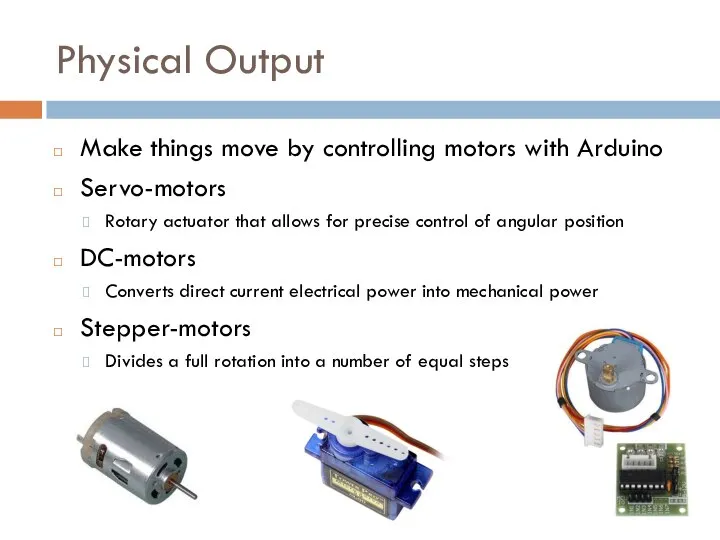
Make things move by controlling motors with Arduino
Servo-motors
Rotary actuator that
Physical Output
Make things move by controlling motors with Arduino
Servo-motors
Rotary actuator that
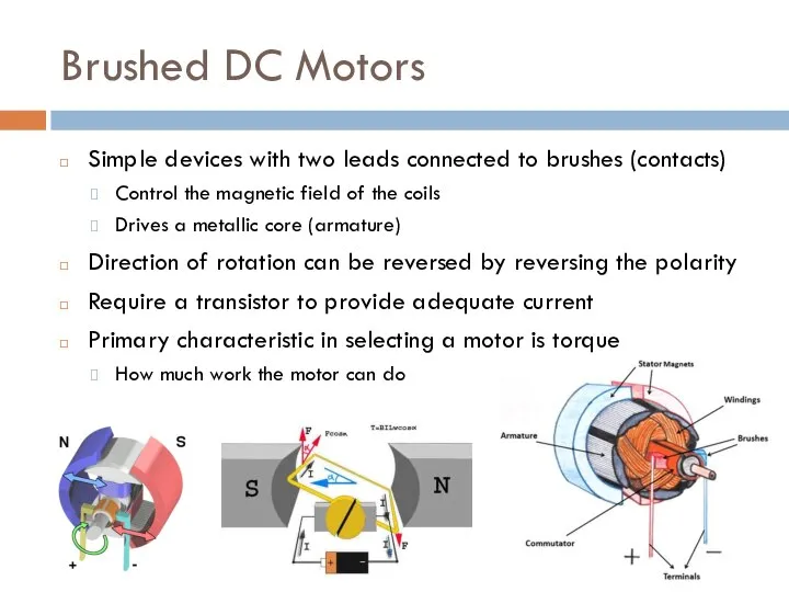
Brushed DC Motors
Simple devices with two leads connected to brushes (contacts)
Control
Brushed DC Motors
Simple devices with two leads connected to brushes (contacts)
Control
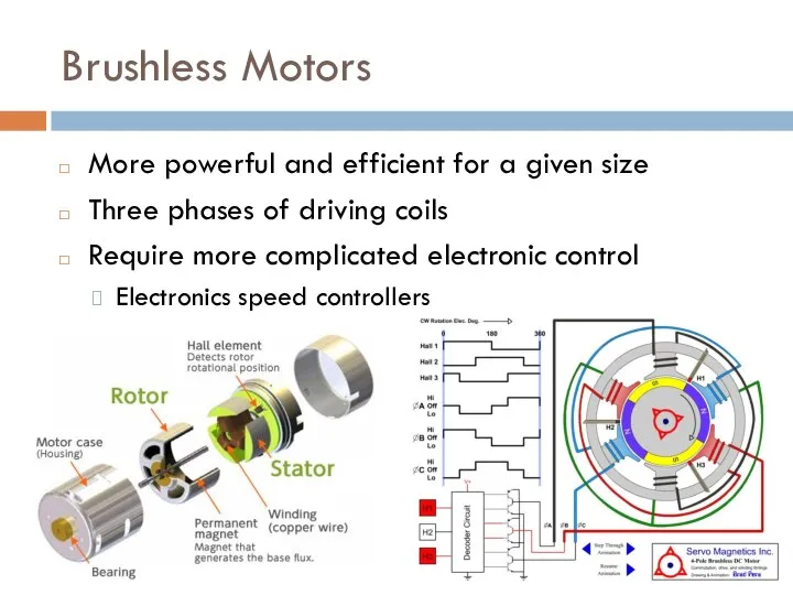
Brushless Motors
More powerful and efficient for a given size
Three phases of
Brushless Motors
More powerful and efficient for a given size
Three phases of
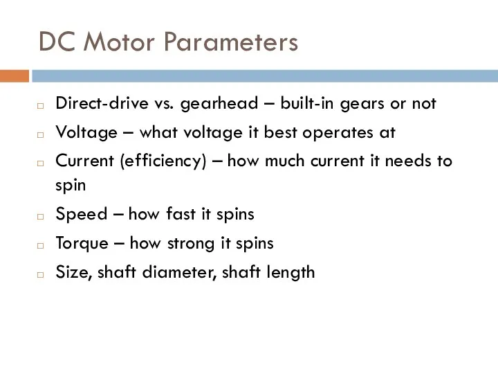
DC Motor Parameters
Direct-drive vs. gearhead – built-in gears or not
Voltage –
DC Motor Parameters
Direct-drive vs. gearhead – built-in gears or not
Voltage –
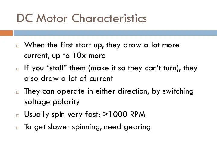
DC Motor Characteristics
When the first start up, they draw a lot
DC Motor Characteristics
When the first start up, they draw a lot
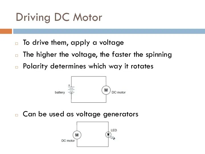
Driving DC Motor
To drive them, apply a voltage
The higher the voltage,
Driving DC Motor
To drive them, apply a voltage
The higher the voltage,
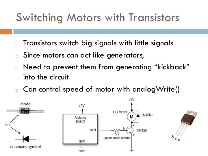
Switching Motors with Transistors
Transistors switch big signals with little signals
Since motors
Switching Motors with Transistors
Transistors switch big signals with little signals
Since motors

Driving a Brushed Motor
const int motorPin = 3;
const int switchPin =
Driving a Brushed Motor
const int motorPin = 3;
const int switchPin =
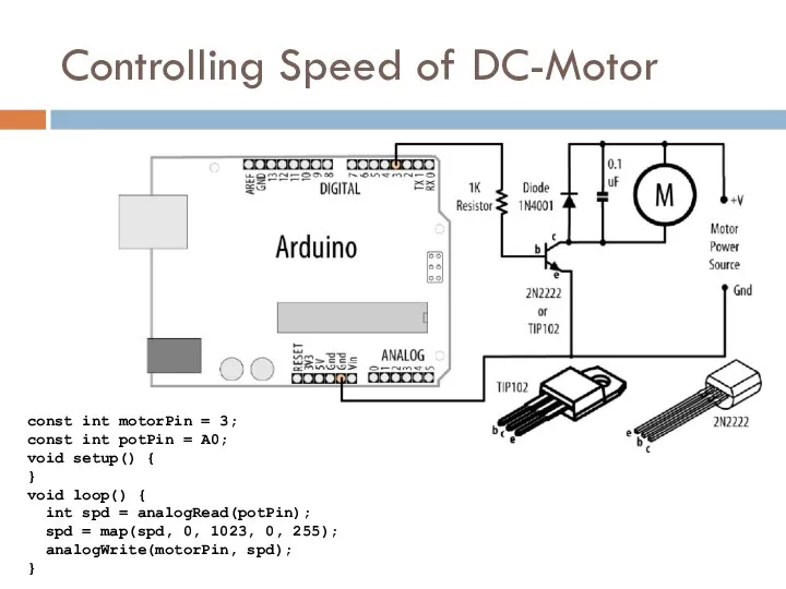
Controlling Speed of DC-Motor
const int motorPin = 3;
const int potPin =
Controlling Speed of DC-Motor
const int motorPin = 3;
const int potPin =
Servo-Motors
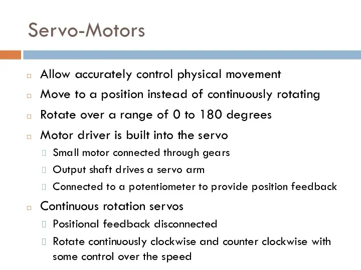
Allow accurately control physical movement
Move to a position instead of continuously
Servo-Motors
Allow accurately control physical movement
Move to a position instead of continuously
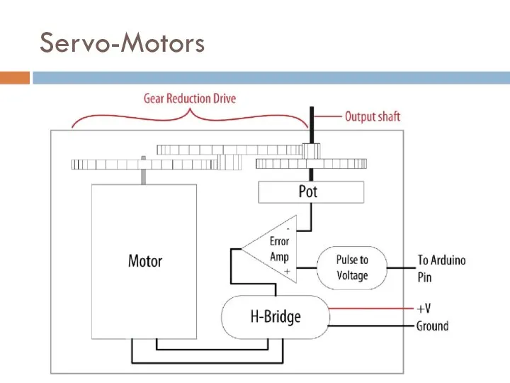
Servo-Motors
Servo-Motors
Servo-Motors
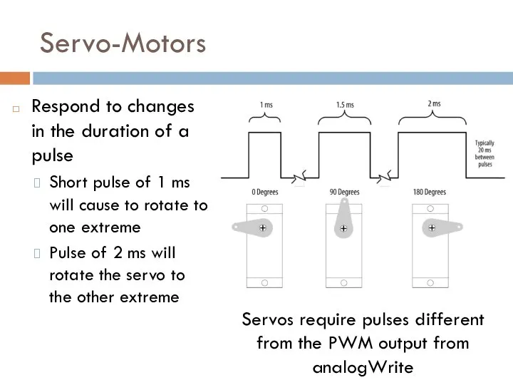
Respond to changes in the duration of a pulse
Short pulse of
Servo-Motors
Respond to changes in the duration of a pulse
Short pulse of
Servo-Motors
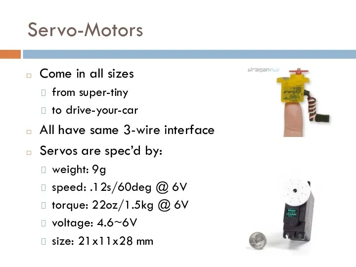
Come in all sizes
from super-tiny
to drive-your-car
All have same 3-wire interface
Servos are
Servo-Motors
Come in all sizes
from super-tiny
to drive-your-car
All have same 3-wire interface
Servos are
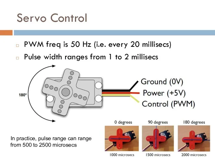
Servo Control
PWM freq is 50 Hz (i.e. every 20 millisecs)
Pulse width
Servo Control
PWM freq is 50 Hz (i.e. every 20 millisecs)
Pulse width
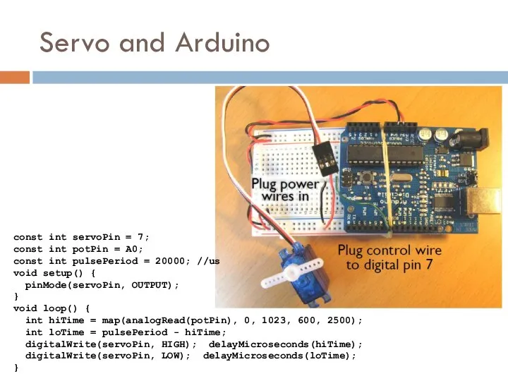
Servo and Arduino
const int servoPin = 7;
const int potPin = A0;
const
Servo and Arduino
const int servoPin = 7;
const int potPin = A0;
const
![Use the Servo library servo.attach(pin[, min][, max]) – attach the servo](/_ipx/f_webp&q_80&fit_contain&s_1440x1080/imagesDir/jpg/1477238/slide-16.jpg)
Use the Servo library
servo.attach(pin[, min][, max]) – attach the servo
pin- the
Use the Servo library
servo.attach(pin[, min][, max]) – attach the servo
pin- the
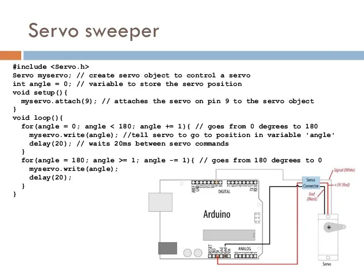
Servo sweeper
#include
Servo myservo; // create servo object to control a
Servo sweeper
#include
Servo myservo; // create servo object to control a
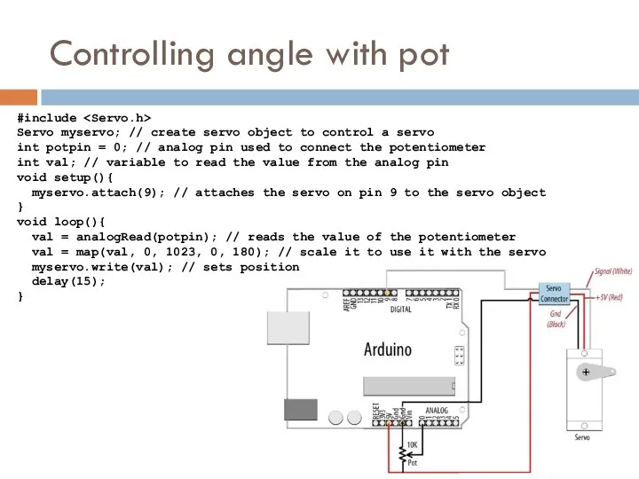
Controlling angle with pot
#include
Servo myservo; // create servo object to
Controlling angle with pot
#include
Servo myservo; // create servo object to
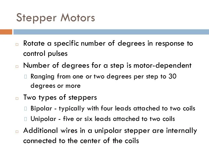
Stepper Motors
Rotate a specific number of degrees in response to control
Stepper Motors
Rotate a specific number of degrees in response to control
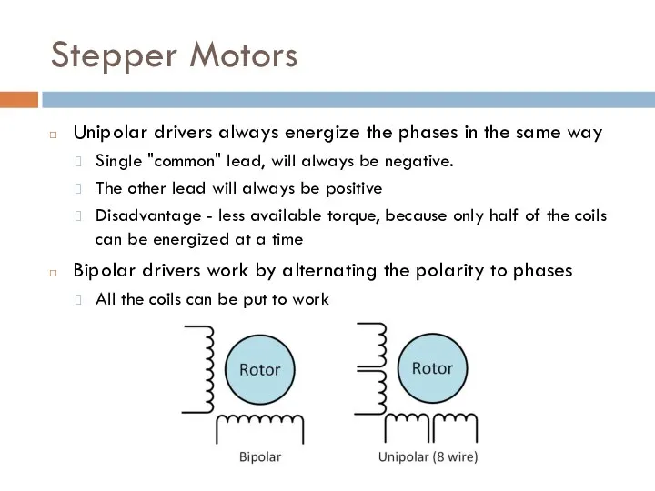
Stepper Motors
Unipolar drivers always energize the phases in the same way
Single
Stepper Motors
Unipolar drivers always energize the phases in the same way
Single
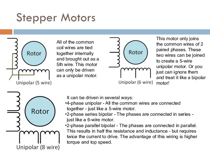
Stepper Motors
All of the common coil wires are tied together internally
Stepper Motors
All of the common coil wires are tied together internally
![Driving a Unipolar Stepper Motor const int stepperPins[4] = {2, 3,](/_ipx/f_webp&q_80&fit_contain&s_1440x1080/imagesDir/jpg/1477238/slide-22.jpg)
Driving a Unipolar Stepper Motor
const int stepperPins[4] = {2, 3, 4,
Driving a Unipolar Stepper Motor
const int stepperPins[4] = {2, 3, 4,
![Driving a Bipolar Stepper Motor const int stepperPins[4] = {2, 3,](/_ipx/f_webp&q_80&fit_contain&s_1440x1080/imagesDir/jpg/1477238/slide-23.jpg)
Driving a Bipolar Stepper Motor
const int stepperPins[4] = {2, 3, 4,
Driving a Bipolar Stepper Motor
const int stepperPins[4] = {2, 3, 4,
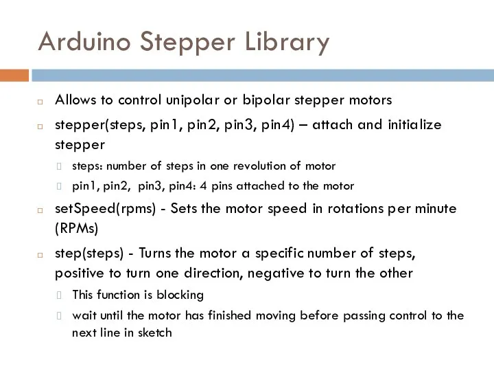
Arduino Stepper Library
Allows to control unipolar or bipolar stepper motors
stepper(steps, pin1,
Arduino Stepper Library
Allows to control unipolar or bipolar stepper motors
stepper(steps, pin1,
 Воздушные стрелки. Схемы связи проводов цепных подвесок на воздушных стрелках
 НАСЫЩЕННЫЙ И НЕНАСЫЩЕННЫЙ ПАР ВЛАЖНОСТЬ ВОЗДУХА КИПЕНИЕ УРОК МОДЕЛИРОВАНИЯ УМЕНИЙ И НАВЫКОВ УЧИТЕЛЬ ФИЗИКИ ЛЕВЧУК М.В. М
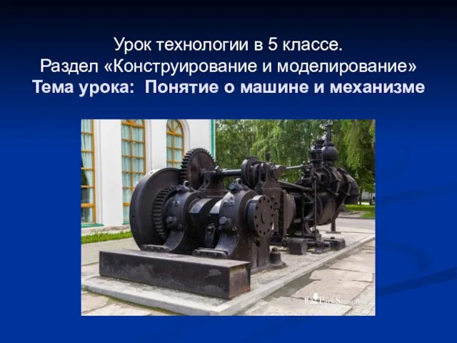 Понятие о машине и механизме
 Закон сохранения механической энергии
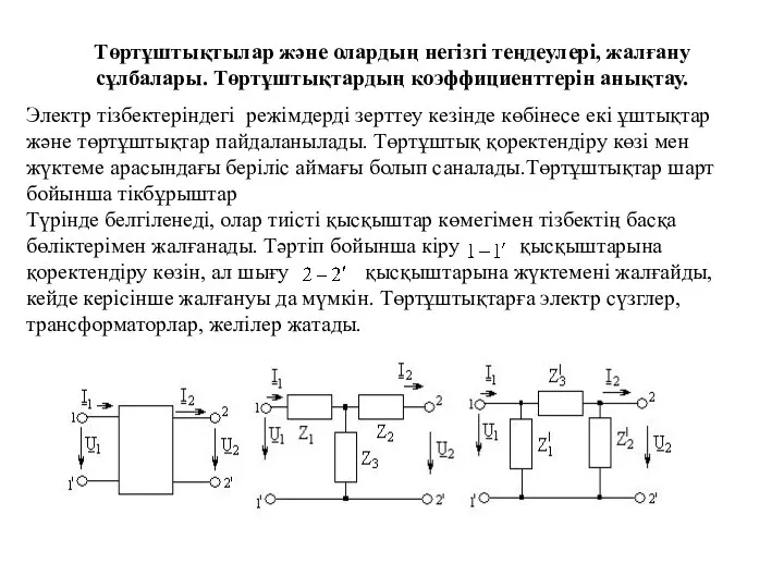 Төртұштықтылар және олардың негізгі теңдеулері, жалғану сұлбалары. Төртұштықтардың коэффициенттерін анықтау
 СУЩЕСТВОВАНИЕ НА ГЛУБИНЕ ПОДГОТОВИЛА: СМАГЛЮК ПОЛИНА
 Лекция 10. Электромагнитные и электродинамические приборы
 Исследование радиального профиля параметров активной среды лазеров с разрядом в полом катоде
 Сила упругости. Закон Гука
 Откуда в наш дом приходит электричество?
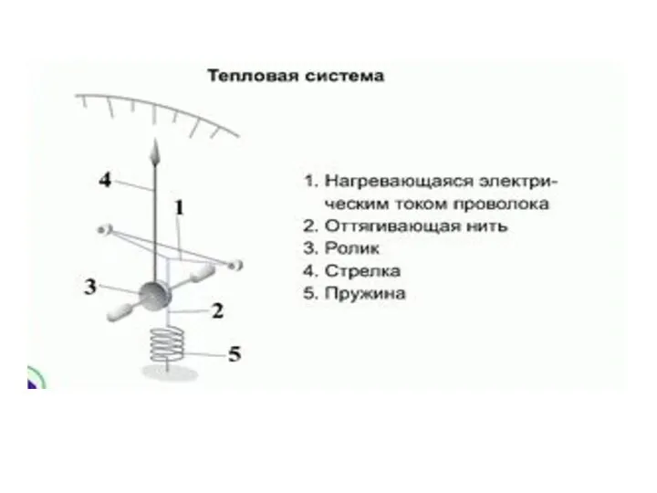 Электрические системы
 Постулаты теории относительности
 Устройство, техническое обслуживание и ремонт топливной аппаратуры
 Электромагнитная волна. Свойства электромагнитных волн
 Импульс. Работа и энергия
 Особенности размещения электронов по орбиталям в атомах малых и больших периодов
 Электронная спектроскопия в анализе органических соединений
 Викторина по физике
 Техническое обслуживание и ремонт с/х машин и оборудования
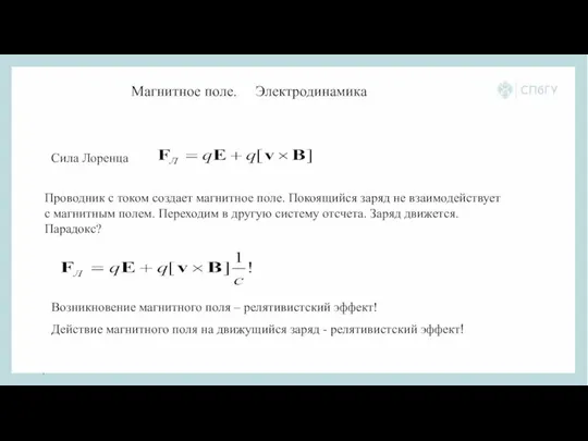 Магнитное поле. Сила Лоренца Электродинамика
 Жарылыстар. Зақымдаушы жарылыс факторлары
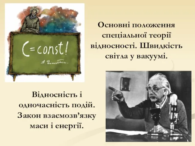 Відносність і одночасність подій. Закон взаємозв’язку маси і енергії
 Строение атома и атомного ядра
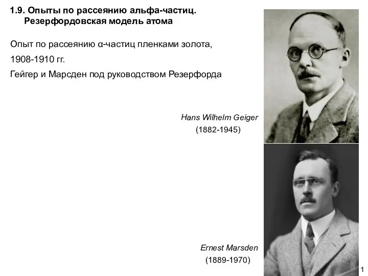 Опыты по рассеянию альфа-частиц. Резерфордовская модель атома. АФ1.9
 Законы физики
 Почему корабли не тонут?
 Презентация по физике. Тема: реактивное движение в животном и растительном мире. Подготовлена: Михальченковой Леной Класс: 9 «б»
 Диэлектрики в электростатическом поле