Setup for VM launch. Using ‘vmxwrite’ and ‘vmxread’ for access to state-information in a Virtual Machine Control Structure
- Setup for VM launch. Using ‘vmxwrite’ and ‘vmxread’ for access to state-information in a Virtual Machine Control Structure

Содержание
- 2. VMXoff VMXon VM and VMM A virtual machine, and its Virtual Machine Manager, each need a
- 3. Access to VMCS Software must initialize the first longword with the CPU’s VMX revision-identifier in advance
- 4. Over one hundred fields! Each field within the VMCS is specified by its unique 32-bit field-encoding
- 5. ‘vmwrite’ Source operand is in register or memory Destination operand is the ‘field-encoding’ for a VMCS
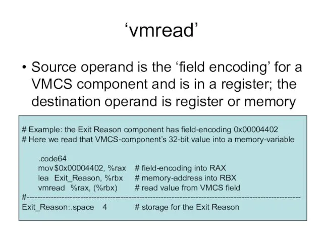
- 6. ‘vmread’ Source operand is the ‘field encoding’ for a VMCS component and is in a register;
- 7. Our ‘machine’ array In our ‘vmxstep3.s’ source-file we create a complete set of memory-variables for all
- 8. Categories of variables The components of the VMCS fall into six categories: Guest-state components Host-state components
- 9. Main Guest-State fields Program memory-segment registers ES, CS, SS, DS, FS, GS System memory-segment registers LDTR,
- 10. For a Virtual-8086 guest-task All program memory-segment registers have 64K segment-limits (0xFFFF) with their ‘access-rights’ equal
- 11. Guest System Segments The base-address and segment-limit for LDTR, TR, GDTR, and IDTR registers can be
- 12. Guest Control Registers Control Register CR0 is required to have its PG, PE, and NE bits
- 13. Guest general registers Most of the guest’s general registers will contain values inherited from the VMM
- 14. Miscellaneous Most other guest-state fields can be left with zero-values for our demo’s purposes But the
- 15. Host-State Our ‘Host’ will execute in 64-bit mode, so its control registers CR0 and CR4 must
- 16. Controls Most of these can be setup with defaults, derived from the VMX Capability MSRs plus
- 17. Example IA32_VMX_PROCBASED_CTLS_MSR (register-index 0x482) 0x67B9FFFE 0401E172 Your proposed value for the corresponding VMCS component must satisfy
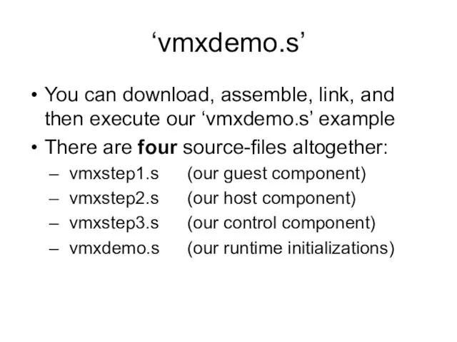
- 18. ‘vmxdemo.s’ You can download, assemble, link, and then execute our ‘vmxdemo.s’ example There are four source-files
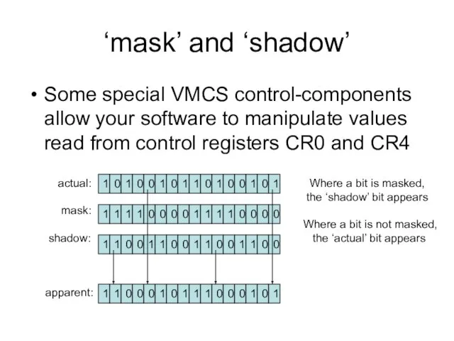
- 19. ‘mask’ and ‘shadow’ Some special VMCS control-components allow your software to manipulate values read from control
- 21. Скачать презентацию
VMXoff
VMXon
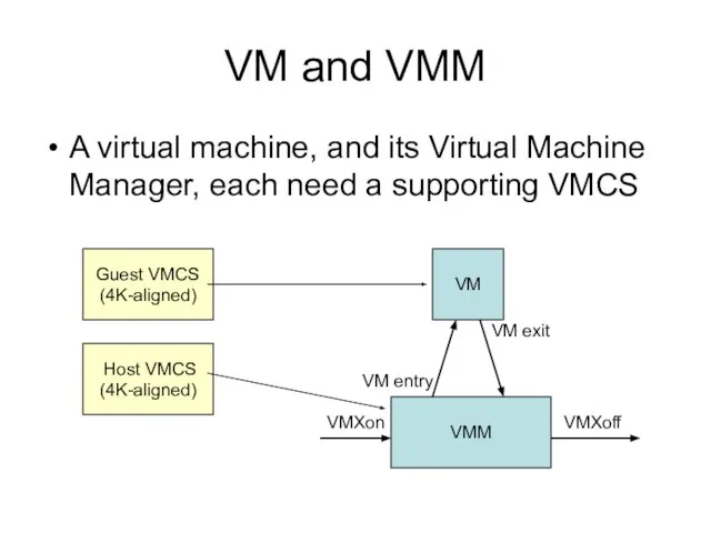
VM and VMM
A virtual machine, and its Virtual Machine Manager, each
VMXoff
VMXon
VM and VMM
A virtual machine, and its Virtual Machine Manager, each
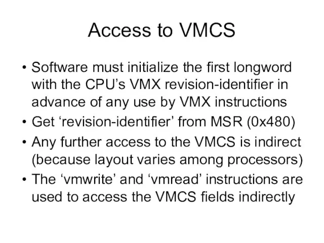
Access to VMCS
Software must initialize the first longword with the CPU’s
Access to VMCS
Software must initialize the first longword with the CPU’s
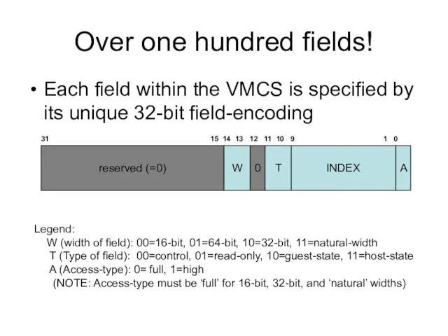
Over one hundred fields!
Each field within the VMCS is specified by
Over one hundred fields!
Each field within the VMCS is specified by
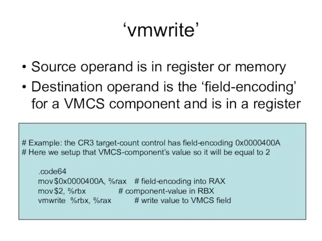
‘vmwrite’
Source operand is in register or memory
Destination operand is the ‘field-encoding’
‘vmwrite’
Source operand is in register or memory
Destination operand is the ‘field-encoding’
‘vmread’
Source operand is the ‘field encoding’ for a VMCS component and
‘vmread’
Source operand is the ‘field encoding’ for a VMCS component and
Our ‘machine’ array
In our ‘vmxstep3.s’ source-file we create a complete set
Our ‘machine’ array
In our ‘vmxstep3.s’ source-file we create a complete set
Categories of variables
The components of the VMCS fall into six categories:
Guest-state
Categories of variables
The components of the VMCS fall into six categories:
Guest-state
Main Guest-State fields
Program memory-segment registers
ES, CS, SS, DS, FS, GS
System
Main Guest-State fields
Program memory-segment registers
ES, CS, SS, DS, FS, GS
System
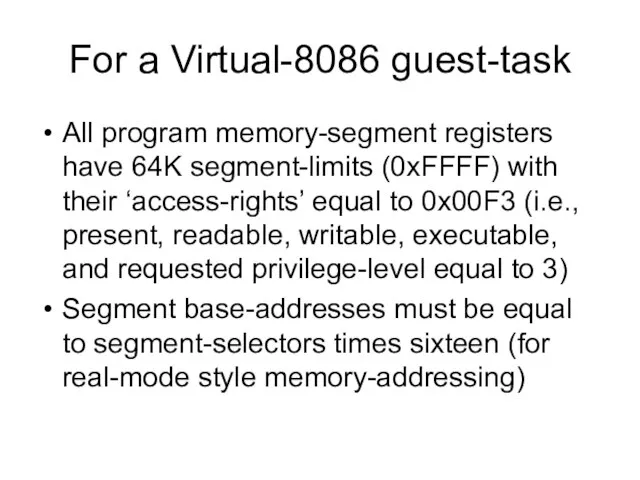
For a Virtual-8086 guest-task
All program memory-segment registers have 64K segment-limits (0xFFFF)
For a Virtual-8086 guest-task
All program memory-segment registers have 64K segment-limits (0xFFFF)
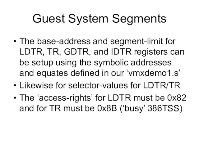
Guest System Segments
The base-address and segment-limit for LDTR, TR, GDTR, and
Guest System Segments
The base-address and segment-limit for LDTR, TR, GDTR, and
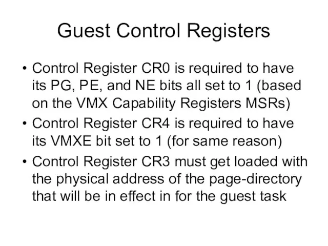
Guest Control Registers
Control Register CR0 is required to have its PG,
Guest Control Registers
Control Register CR0 is required to have its PG,
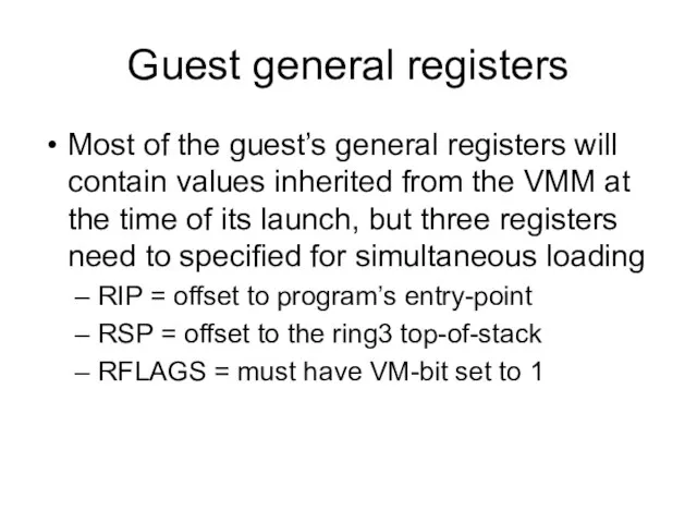
Guest general registers
Most of the guest’s general registers will contain values
Guest general registers
Most of the guest’s general registers will contain values
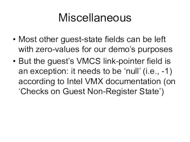
Miscellaneous
Most other guest-state fields can be left with zero-values for
Miscellaneous
Most other guest-state fields can be left with zero-values for
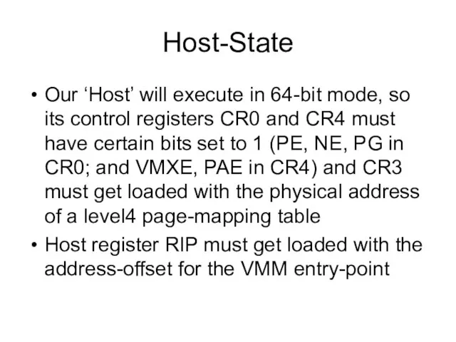
Host-State
Our ‘Host’ will execute in 64-bit mode, so its control registers
Host-State
Our ‘Host’ will execute in 64-bit mode, so its control registers
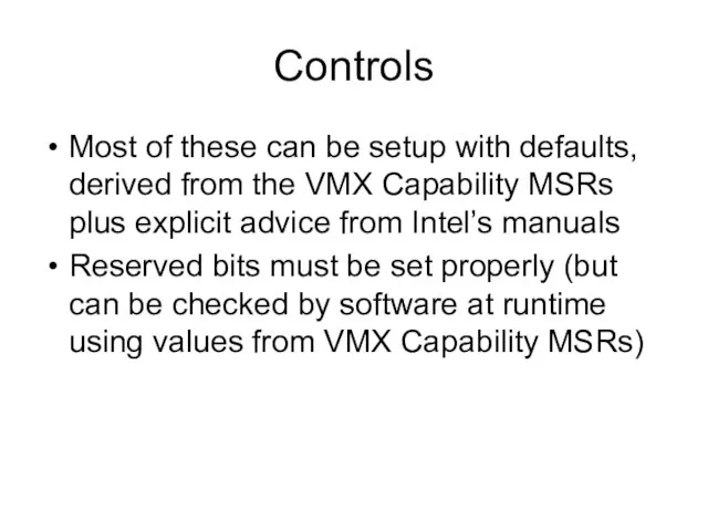
Controls
Most of these can be setup with defaults, derived from the
Controls
Most of these can be setup with defaults, derived from the
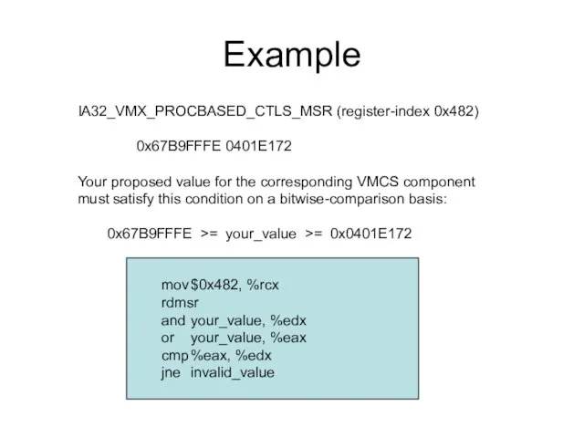
Example
IA32_VMX_PROCBASED_CTLS_MSR (register-index 0x482)
0x67B9FFFE 0401E172
Your proposed value for the corresponding VMCS component
must
Example
IA32_VMX_PROCBASED_CTLS_MSR (register-index 0x482)
0x67B9FFFE 0401E172
Your proposed value for the corresponding VMCS component
must
‘vmxdemo.s’
You can download, assemble, link, and then execute our ‘vmxdemo.s’
‘vmxdemo.s’
You can download, assemble, link, and then execute our ‘vmxdemo.s’
‘mask’ and ‘shadow’
Some special VMCS control-components allow your software to manipulate
‘mask’ and ‘shadow’
Some special VMCS control-components allow your software to manipulate
 Представление информации в памяти компьютера
 Поиск записей в табличной базе данных с помощью фильтров
 Программный исполнитель на уроках информатики
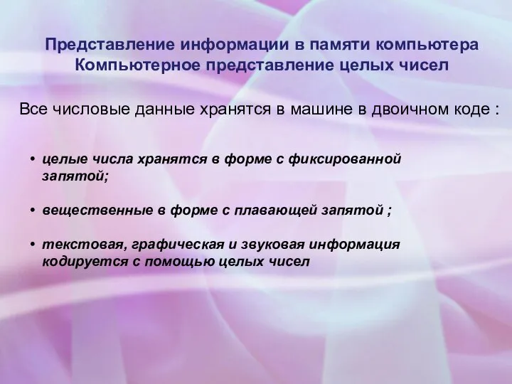
 Представление числовой информации в компьютере Компьютерное представление целых чисел
  Создание электронных учебников с Constructor Electronic books
 Устройство обработки информации Процессор
 Информационные ресурсы общества
 Аттестационная работа. Методическая разработка исследовательского урока Знакомство с клавиатурой
 Интернет. Безопасность в сети Интернет
 Встроенные объекты языка JavaScript
 Презентация "ЗНАКОМСТВО ГРАФИЧЕСКИМ РЕДАКТОРОМ KOLOURPAINT" - скачать презентации по Информатике
 Проектирование баз данных. Нормальные формы. Лекция 1
 Capturing Light… in man and machine
 CSV в Python
 Презентация Операторы ветвления
 Операционные среды, системы и оболочки. Логическая организация файлов
 З Україною в серці
 Фіксікі. Сімка
 Применение информационной среды для обработки данных при проведении строительномонтажных работ
 Презентація на тему «Електронна пошта»
  Архитектура ЭВМ
 Процедуры и функции в Паскале
 Правила безопасного поведения в сети Интернет
 Microsoft Office. Программы для работы с текстом
 О применении контрольно-кассовой техники
 Информационное общество
 Информатика. Основные понятия и определения
 Информационно-аналитические центры