- GT-I9105P Training Manual HW F

Содержание
- 2. Notice : All functionality, features, specifications and other product information provided in this document including, but
- 3. Contents Concept & Main features Block Diagram Component & Location Disassembly and Assembly Trouble shooting Calibration
- 4. Concept & Main features
- 5. Contents Concept & Main features Block Diagram Component & Location Disassembly and Assembly Trouble shooting Calibration
- 6. Block Diagram (Baseband)
- 7. Block Diagram (RF)
- 8. Contents Concept & Main features Block Diagram Component & Location Disassembly and Assembly Trouble shooter Calibration
- 9. PCB Diagram (TOP)
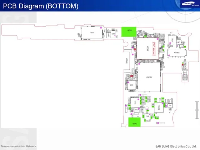
- 10. PCB Diagram (BOTTOM)
- 11. NFC Main Top Volume Keys Movi-MCP AP/CP Power Keys BT/WIFI/FM 8M Camera Tranceiver 2G PAM SAW
- 12. Main Bottom 3G PAM GPS Touch Key Connector SIM CON RF Switch Flash LED OLED TSP
- 13. Ass’y 3.5pi Earjack Motor BT/WiFi ANT 8M Camera Micro SD TSP Controller Speaker 2M Camera SIM
- 14. Contents Concept & Main features Block Diagram Component & Location Disassembly and Assembly Trouble shooting Calibration
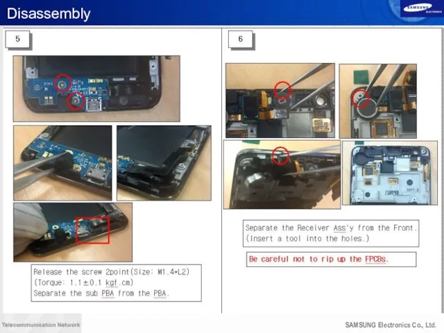
- 15. Disassembly
- 16. Disassembly
- 17. Disassembly
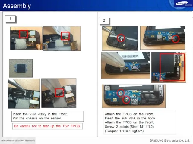
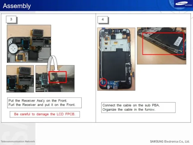
- 18. Assembly
- 19. Assembly
- 20. Assembly
- 21. Assembly
- 22. Contents Concept & Main features Block Diagram Component & Location Disassembly and Assembly Trouble shooting Calibration
- 23. PBA Diagram (TOP)
- 24. PBA Diagram (BOTTOM)
- 25. Power ON
- 26. Initial (Lock up)
- 27. No service
- 28. SIM Part
- 29. Charging Part
- 30. Main MIC
- 31. Sub MIC
- 32. Speaker
- 33. Receiver
- 34. BT/WiFi
- 35. BT/WiFi
- 36. FM Radio
- 37. LCD
- 38. TSP
- 39. TSP
- 40. 8M CAM
- 41. 2M CAM
- 42. GSM1800 RX
- 43. WCDMA Band1 Rx
- 44. WCDMA Band1 Rx
- 45. WCDMA Band2/GSM1900 RX
- 46. WCDMA Band2/GSM1900 RX
- 47. WCDMA Band5 / GSM 850 RX
- 48. WCDMA Band5 / GSM 850 RX
- 49. WCDMA Band8 / GSM900 RX
- 50. WCDMA Band8 / GSM900 RX
- 51. GSM 850/GSM900 TX
- 52. GSM 850/GSM900 TX
- 53. DCS/PCS TX
- 54. DCS/PCS TX
- 55. WCDMA Band1 TX
- 56. WCDMA Band1 TX
- 57. WCDMA Band2 TX
- 58. WCDMA
- 59. WCDMA Band5 Tx
- 60. WCDMA Band5 TX
- 61. WCDMA Band8 TX
- 63. MHL
- 65. OTG
- 66. NFC
- 67. NFC
- 68. Contents Concept & Main features Block Diagram Component & Location Disassembly and Assembly Trouble shooting Calibration
- 69. Calibration start Execute Infineon_RFCAL_V44.exe DGS Read : un-check FDT Option : if you have License :
- 70. Calibration 1. Message “Wating.ST Signal 2. Click the M/A button 3. Change Automatic mode to Manual
- 72. Скачать презентацию
Notice :
All functionality, features, specifications and other product
information provided in this document including, but not limited
to, the benefits, design, pricing, components, performance,
availability, and capabilities of the product are subject to change
without notice or obligation. Samsung reserves the right to make changes to this document and the product described herein, at anytime, without obligation on Samsung to provide notification of
such change.
Contents
Concept & Main features
Block Diagram
Component & Location
Disassembly and Assembly
Trouble shooting
Calibration
MHL
Contents
Concept & Main features
Block Diagram
Component & Location
Disassembly and Assembly
Trouble shooting
Calibration
MHL

Concept & Main features
Concept & Main features

Contents
Concept & Main features
Block Diagram
Component & Location
Disassembly and Assembly
Trouble shooting
Calibration
Contents
Concept & Main features
Block Diagram
Component & Location
Disassembly and Assembly
Trouble shooting
Calibration

Block Diagram (Baseband)
Block Diagram (Baseband)
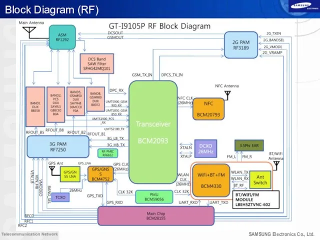
Block Diagram (RF)
Block Diagram (RF)

Contents
Concept & Main features
Block Diagram
Component & Location
Disassembly and Assembly
Trouble shooter
Calibration
Contents
Concept & Main features
Block Diagram
Component & Location
Disassembly and Assembly
Trouble shooter
Calibration
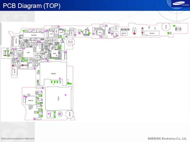
PCB Diagram (TOP)
PCB Diagram (TOP)
PCB Diagram (BOTTOM)
PCB Diagram (BOTTOM)

NFC
Main Top
Volume Keys
Movi-MCP
AP/CP
Power Keys
BT/WIFI/FM
8M Camera
Tranceiver
2G PAM
SAW Filter
CAM Flash IC
Magnetic Sensor
Gyro/Acc.
NFC
Main Top
Volume Keys
Movi-MCP
AP/CP
Power Keys
BT/WIFI/FM
8M Camera
Tranceiver
2G PAM
SAW Filter
CAM Flash IC
Magnetic Sensor
Gyro/Acc.

Main Bottom
3G PAM
GPS
Touch Key Connector
SIM CON
RF Switch
Flash LED
OLED TSP Connector
Earjack/Motor/RCV CON
GPS
Main Bottom
3G PAM
GPS
Touch Key Connector
SIM CON
RF Switch
Flash LED
OLED TSP Connector
Earjack/Motor/RCV CON
GPS

Ass’y
3.5pi Earjack
Motor
BT/WiFi ANT
8M Camera
Micro SD
TSP Controller
Speaker
2M Camera
SIM Card
Receiver
Light/Proximity Sensors
Mic
Main ANT Contact
GPS
Ass’y
3.5pi Earjack
Motor
BT/WiFi ANT
8M Camera
Micro SD
TSP Controller
Speaker
2M Camera
SIM Card
Receiver
Light/Proximity Sensors
Mic
Main ANT Contact
GPS

Contents
Concept & Main features
Block Diagram
Component & Location
Disassembly and Assembly
Trouble shooting
Calibration
Contents
Concept & Main features
Block Diagram
Component & Location
Disassembly and Assembly
Trouble shooting
Calibration

Disassembly
Disassembly

Disassembly
Disassembly
Disassembly
Disassembly
Assembly
Assembly
Assembly
Assembly

Assembly
Assembly

Assembly
Assembly

Contents
Concept & Main features
Block Diagram
Component & Location
Disassembly and Assembly
Trouble shooting
Calibration
Contents
Concept & Main features
Block Diagram
Component & Location
Disassembly and Assembly
Trouble shooting
Calibration

PBA Diagram (TOP)
PBA Diagram (TOP)

PBA Diagram (BOTTOM)
PBA Diagram (BOTTOM)

Power ON
Power ON

Initial (Lock up)
Initial (Lock up)
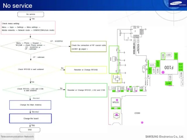
No service
No service

SIM Part
SIM Part
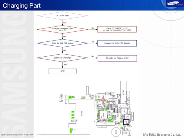
Charging Part
Charging Part

Main MIC
Main MIC
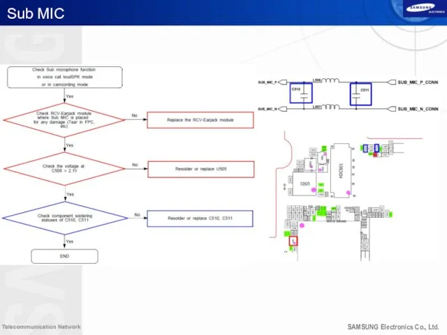
Sub MIC
Sub MIC
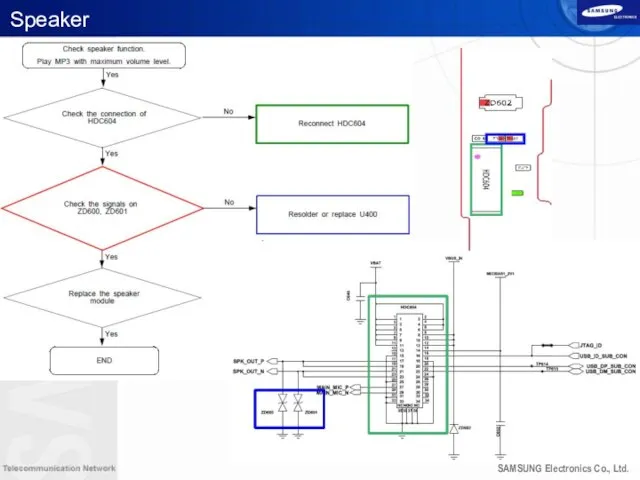
Speaker
Speaker

Receiver
Receiver

BT/WiFi
BT/WiFi

BT/WiFi
BT/WiFi
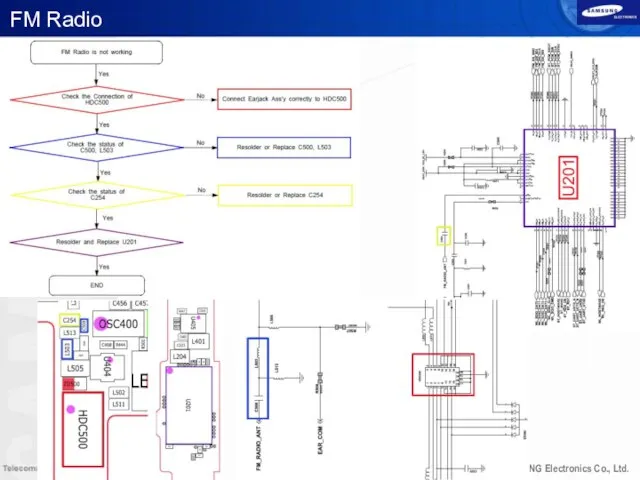
FM Radio
FM Radio

LCD
LCD
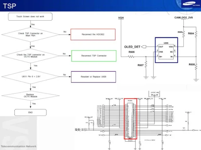
TSP
TSP
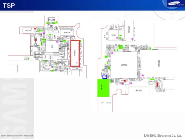
TSP
TSP

8M CAM
8M CAM

2M CAM
2M CAM
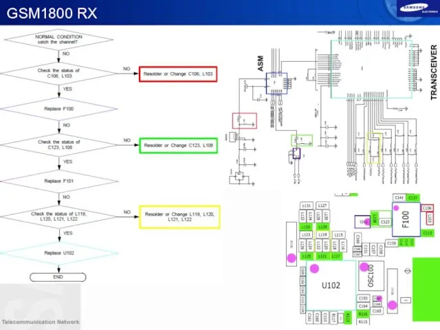
GSM1800 RX
GSM1800 RX

WCDMA Band1 Rx
WCDMA Band1 Rx

WCDMA Band1 Rx
WCDMA Band1 Rx

WCDMA Band2/GSM1900 RX
WCDMA Band2/GSM1900 RX

WCDMA Band2/GSM1900 RX
WCDMA Band2/GSM1900 RX

WCDMA Band5 / GSM 850 RX
WCDMA Band5 / GSM 850 RX

WCDMA Band5 / GSM 850 RX
WCDMA Band5 / GSM 850 RX

WCDMA Band8 / GSM900 RX
WCDMA Band8 / GSM900 RX

WCDMA Band8 / GSM900 RX
WCDMA Band8 / GSM900 RX

GSM 850/GSM900 TX
GSM 850/GSM900 TX

GSM 850/GSM900 TX
GSM 850/GSM900 TX
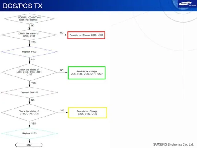
DCS/PCS TX
DCS/PCS TX

DCS/PCS TX
DCS/PCS TX

WCDMA Band1 TX
WCDMA Band1 TX

WCDMA Band1 TX
WCDMA Band1 TX

WCDMA Band2 TX
WCDMA Band2 TX
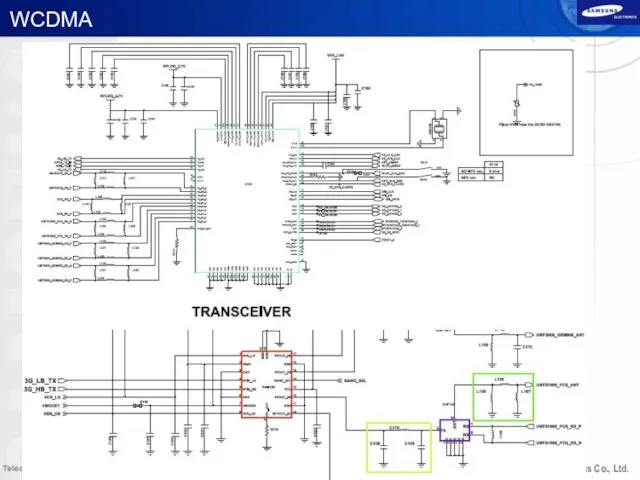
WCDMA
WCDMA

WCDMA Band5 Tx
WCDMA Band5 Tx
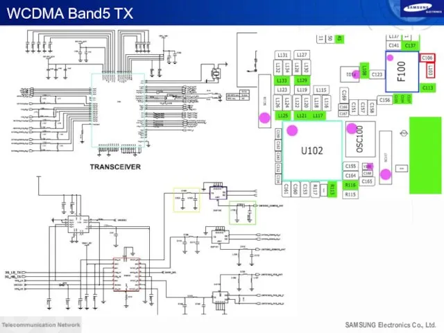
WCDMA Band5 TX
WCDMA Band5 TX
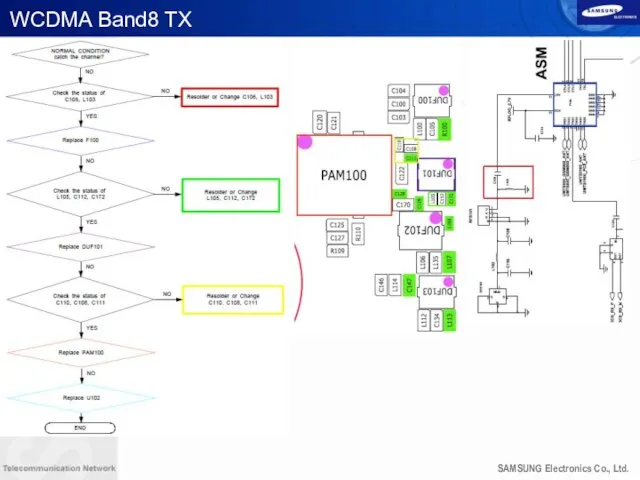
WCDMA Band8 TX
WCDMA Band8 TX


MHL
MHL


OTG
OTG
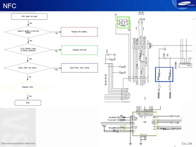
NFC
NFC

NFC
NFC
Contents
Concept & Main features
Block Diagram
Component & Location
Disassembly and Assembly
Trouble shooting
Calibration
Contents
Concept & Main features
Block Diagram
Component & Location
Disassembly and Assembly
Trouble shooting
Calibration
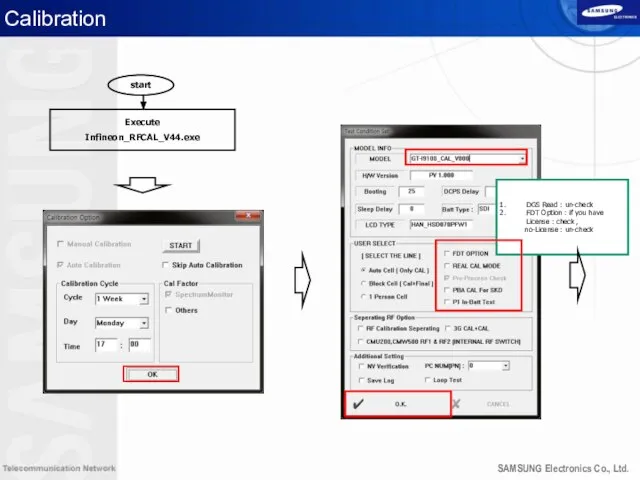
Calibration
start
Execute
Infineon_RFCAL_V44.exe
DGS Read : un-check
FDT Option : if you have License
Calibration
start
Execute
Infineon_RFCAL_V44.exe
DGS Read : un-check
FDT Option : if you have License

Calibration
1. Message “Wating.ST Signal
2. Click the M/A button
3. Change Automatic mode
Calibration
1. Message “Wating.ST Signal
2. Click the M/A button
3. Change Automatic mode
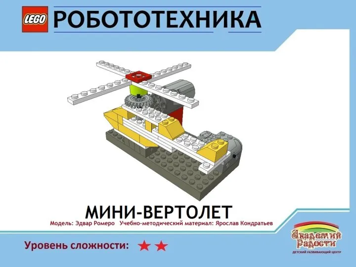 Lego: Small Helicopter, мини-вертолет
 Моющий пылесос
 От идеи до бизнеса. Конвейер проектов
 Как заработать в Интернете
 Предложение по заправке автотранспорта с использованием топливной карты Вездеход Online
 Бизнес предложение Ростелеком
 Модель учебно-делового центра ООО МебельСтрой
 Маркетинговые исследования
 Современные охлаждающие жидкости. Антифриз
 Соки Волжский посад. ООО Фирма Нектар
 Posm free. Сеть магазинов
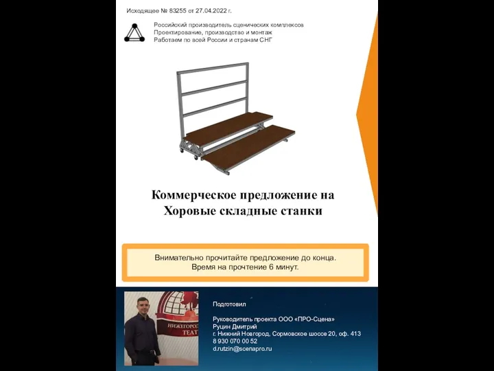 Коммерческое предложение на Хоровые складные станки
 RALPH LAUREN. Історія успіху
 Характерные черты рекламы в Эквадоре
 Салонные уходы KAYPRO
 Удовые ароматы. Лекция 19
 Отдел молодежной одежды
 Разработка фирменного стиля для книжного магазина Азия в обложке
 Готовимся к свадьбе с удовольствием
 Санаторий Дубовая роща КМВ, г. Железноводск
 Группа ГАЗ
 Чистые эфирные масла
 Факторный анализ показателей рентабельности компании
 Очки и мода. Салон оптики
 Деловой этикет сотрудников гостиницы Hilton Moscow Leningradskaya
 New speech
 Константин – ботанический питомник
 Ребрендинг, как инструмент развития бренда