- Furnaces bases operation

Содержание
- 2. Furnaces of the past, aero-fuel or gas melting, very high consumption
- 3. Port End furnace standard in verallia significant reduction in consumption by regeneration (T ° of combustion
- 4. Electric furnaces, very limited surface and pull
- 5. Port End furnace standard in verallia Front wall Ports necks Regenerators
- 6. Theoretical consumption Formula of a furnace: Main parameters of the furnace design: Thermal losses of the
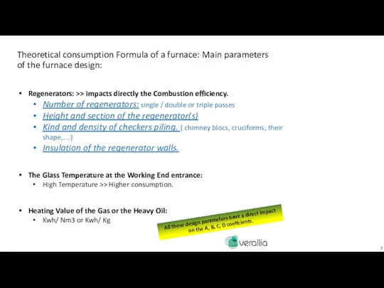
- 7. Theoretical consumption Formula of a furnace: Main parameters of the furnace design: Regenerators: >> impacts directly
- 8. Theoretical consumption Formula of a furnace: Given by the Furnace design: Consump.= k x [ A
- 9. The operation parameter necessary for a good steering: With pull or cullet% or boosting Power changes.
- 10. In the production of flint or extra flint glass (low concentration of iron oxide Fe2O3), the
- 11. Dark Reduced Glass (High concentration of Fe2O3 and FeO): In the production of colored glass the
- 12. In the case of Flint Glass. After 2,9T/m2, the additional tons are melted by the boosting.
- 13. Theoritical Consumption equation of a furnace: in Flint Glass. BTS Oil PCI = 9700 Kcal/Kg Theoretical
- 14. Theoritical Consumption equation of a furnace: in flint. (It depends of the % of cullet) Same
- 15. In the case of Dark Glass: We need the boosting earlier at lower pull. In certain
- 16. Theoritical Consumption equation of a furnace: in Dark Glass. We need the boosting earlier, at lower
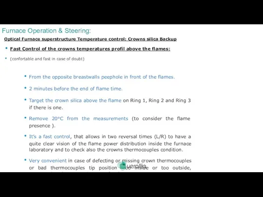
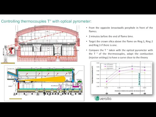
- 17. Optical Furnace superstructure Temperature control: Crowns silica Backup Fast Control of the crowns temperatures profil above
- 18. Optical Furnace superstructure Temperature control: Crowns silica Backup Fast Control of the crowns temperatures profil above
- 19. Furnace maximum admissible temperatures for each furnace area : 1510°C Regenerator Port entrance Wall/Arch 1615°C Optical
- 20. Exemple of batch piles distribution: OK NOT OK = Seeds risks Dogs houses : batch piles
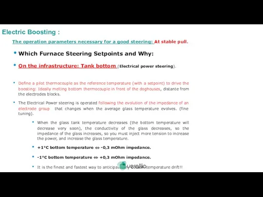
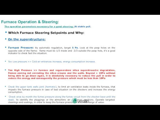
- 21. The operation parameters necessary for a good steering: At stable pull. Which Furnace Steering Setpoints and
- 22. The operation parameters necessary for a good steering: At stable pull. Which Furnace Steering Setpoints and
- 23. The operation parameters necessary for a good steering: At stable pull. Which Furnace Steering Setpoints and
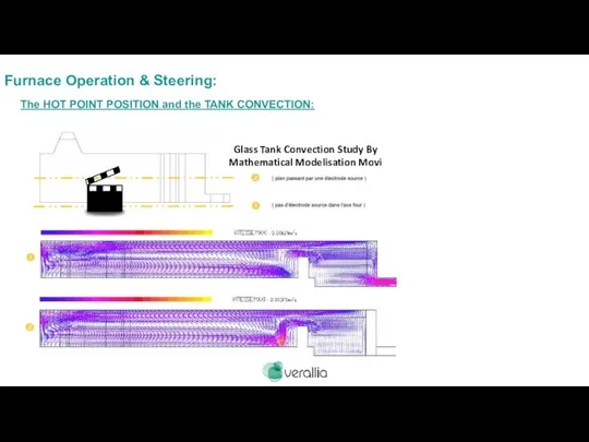
- 24. At the end of the campaign, we see perfectly the corrosion striations of convection along the
- 25. Furnace Operation & Steering: The HOT POINT POSITION and the TANK CONVECTION:
- 26. D. Grand MP & EV 2012 Furnace Operation & Steering: The HOT POINT POSITION and the
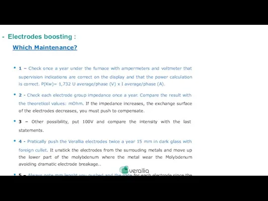
- 27. Which Maintenance? 1 – Check once a year under the furnace with ampermeters and voltmeter that
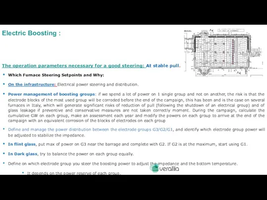
- 28. Power management of boosting groups: if we spend a lot of power on 1 single group
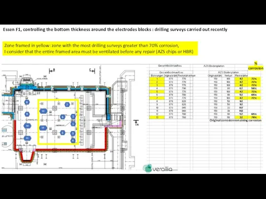
- 29. Essen F1 2020 (Sorg electrodes) : Current situation on the G melting electrode blocks N °
- 30. corrosion Original remaining corrosion Zone framed in yellow: zone with the most drilling surveys greater than
- 31. Thermocouple installed 10mm in 2nd layer of fire clay and every m² Cooling holes : Drill
- 32. Bottom cooling system: Zorya F2 bottom cooling system, the best system is this one because it
- 33. Bottom cooling System : Zorya F2 collectors
- 34. Essen F1 volution Electrodes T° / Pushing : the first conclusion that we can make: the
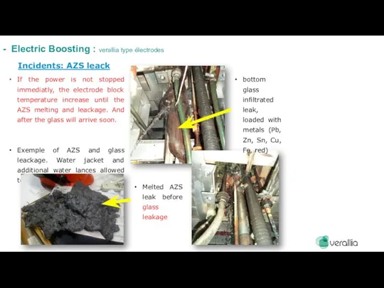
- 35. Incidents: AZS leack If the power is not stopped immediatly, the electrode block temperature increase until
- 36. Incidents: metal particles in foreign cullet and accumulation on the bottom of the furnace Diminution of
- 37. Bubblers: Management of bubblers / Risk When FLAME transfert to the bottom is saturated. Superstructure temperature
- 38. The ceramic bubbler: Alumina Bubbler block completly worn. 7 cm remaining thickness after the furnace stop
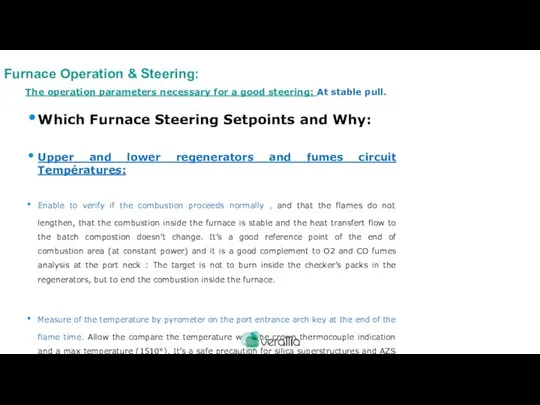
- 39. The operation parameters necessary for a good steering: At stable pull. Which Furnace Steering Setpoints and
- 40. The operation parameters necessary for a good steering: At stable pull. Which Furnace Steering Setpoints and
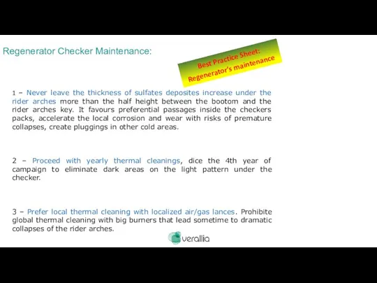
- 41. Regenerator Checker Maintenance: 1 – Never leave the thickness of sulfates deposites increase under the rider
- 42. 5 – Control moisture and plasticity of the batch . Pay attention to the fines raw
- 43. Restrictions of checkers section induce dramatic diminution of combustion yield, end the furnace consumption increases. Regenerator
- 45. Скачать презентацию
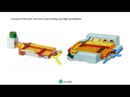
Furnaces of the past, aero-fuel or gas melting, very high consumption
Furnaces of the past, aero-fuel or gas melting, very high consumption
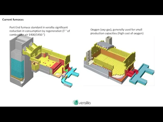
Port End furnace standard in verallia significant reduction in consumption by
Port End furnace standard in verallia significant reduction in consumption by
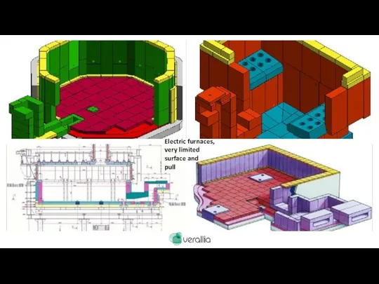
Electric furnaces,
very limited
surface and
pull
Electric furnaces,
very limited
surface and
pull
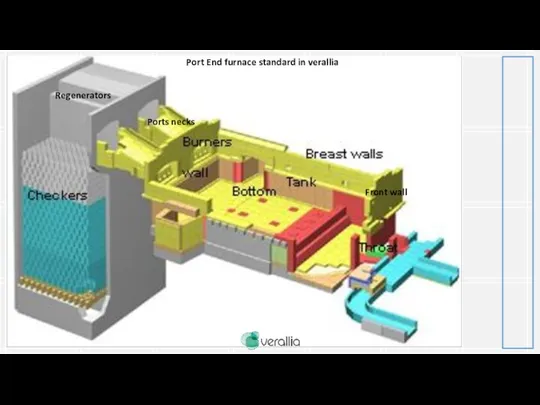
Port End furnace standard in verallia
Front wall
Ports necks
Regenerators
Port End furnace standard in verallia
Front wall
Ports necks
Regenerators
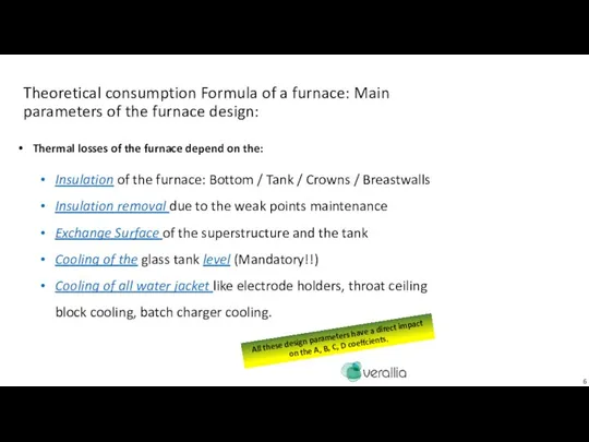
Theoretical consumption Formula of a furnace: Main parameters of the furnace
Theoretical consumption Formula of a furnace: Main parameters of the furnace
Theoretical consumption Formula of a furnace: Main parameters of the furnace
Theoretical consumption Formula of a furnace: Main parameters of the furnace
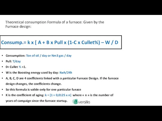
Theoretical consumption Formula of a furnace: Given by the Furnace design:
Consump.=
Theoretical consumption Formula of a furnace: Given by the Furnace design:
Consump.=
The operation parameter necessary for a good steering: With pull or
The operation parameter necessary for a good steering: With pull or
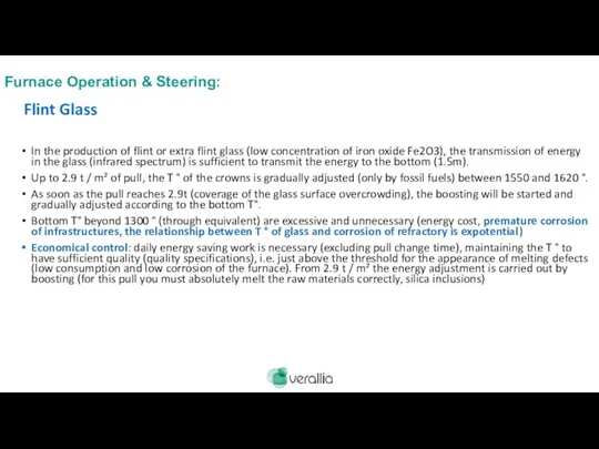
In the production of flint or extra flint glass (low concentration
In the production of flint or extra flint glass (low concentration
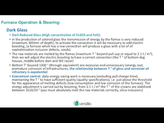
Dark Reduced Glass (High concentration of Fe2O3 and FeO):
In the production
Dark Reduced Glass (High concentration of Fe2O3 and FeO):
In the production
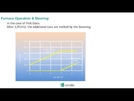
In the case of Flint Glass.
After 2,9T/m2, the additional tons
In the case of Flint Glass. After 2,9T/m2, the additional tons
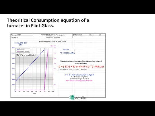
Theoritical Consumption equation of a furnace: in Flint Glass.
BTS Oil
PCI =
Theoritical Consumption equation of a furnace: in Flint Glass.
BTS Oil
PCI =
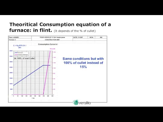
Theoritical Consumption equation of a furnace: in flint. (It depends of
Theoritical Consumption equation of a furnace: in flint. (It depends of
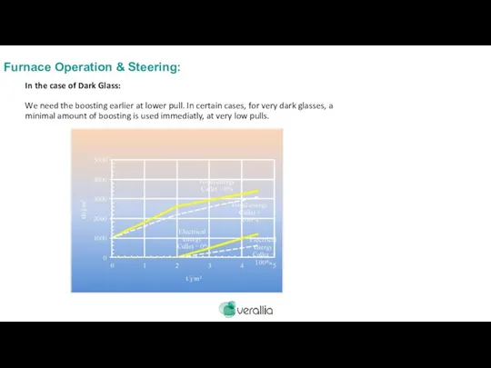
In the case of Dark Glass:
We need the boosting earlier
In the case of Dark Glass: We need the boosting earlier
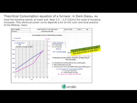
Theoritical Consumption equation of a furnace: in Dark Glass. We need
Theoritical Consumption equation of a furnace: in Dark Glass. We need
Optical Furnace superstructure Temperature control: Crowns silica Backup
Fast Control of the
Optical Furnace superstructure Temperature control: Crowns silica Backup
Fast Control of the
Optical Furnace superstructure Temperature control: Crowns silica Backup
Fast Control of the
Optical Furnace superstructure Temperature control: Crowns silica Backup
Fast Control of the
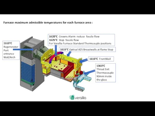
Furnace maximum admissible temperatures for each furnace area :
1510°C Regenerator Port
Furnace maximum admissible temperatures for each furnace area :
1510°C Regenerator Port
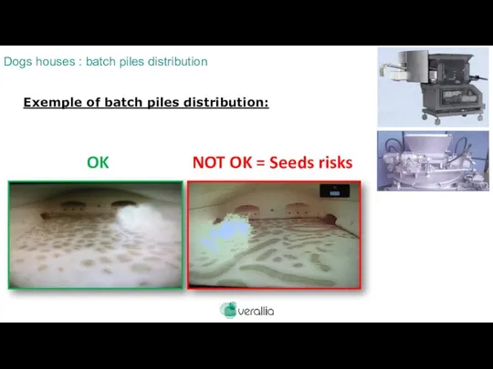
Exemple of batch piles distribution:
OK
NOT OK = Seeds risks
Dogs houses :
OK
NOT OK = Seeds risks
Dogs houses :
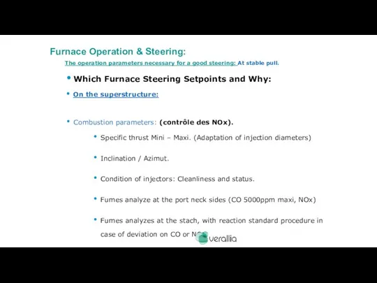
The operation parameters necessary for a good steering: At stable pull.
Which
The operation parameters necessary for a good steering: At stable pull.
Which
The operation parameters necessary for a good steering: At stable pull.
Which
The operation parameters necessary for a good steering: At stable pull.
Which
The operation parameters necessary for a good steering: At stable pull.
Which
The operation parameters necessary for a good steering: At stable pull.
Which
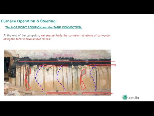
At the end of the campaign, we see perfectly the corrosion
At the end of the campaign, we see perfectly the corrosion
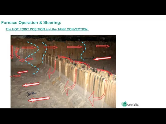
<< Throat
Furnace Operation & Steering:
The HOT POINT POSITION and the TANK
<< Throat
Furnace Operation & Steering:
The HOT POINT POSITION and the TANK
D. Grand MP & EV 2012
Furnace Operation & Steering:
The HOT POINT
D. Grand MP & EV 2012
Furnace Operation & Steering:
The HOT POINT
Which Maintenance?
1 – Check once a year under the furnace
Which Maintenance?
1 – Check once a year under the furnace
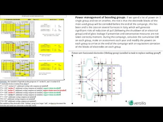
Power management of boosting groups: if we spend a lot of
Power management of boosting groups: if we spend a lot of
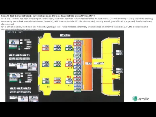
Essen F1 2020 (Sorg electrodes) : Current situation on the G
Essen F1 2020 (Sorg electrodes) : Current situation on the G
corrosion
Original
remaining
corrosion
Zone framed in yellow: zone with the most drilling surveys greater
corrosion
Original
remaining
corrosion
Zone framed in yellow: zone with the most drilling surveys greater
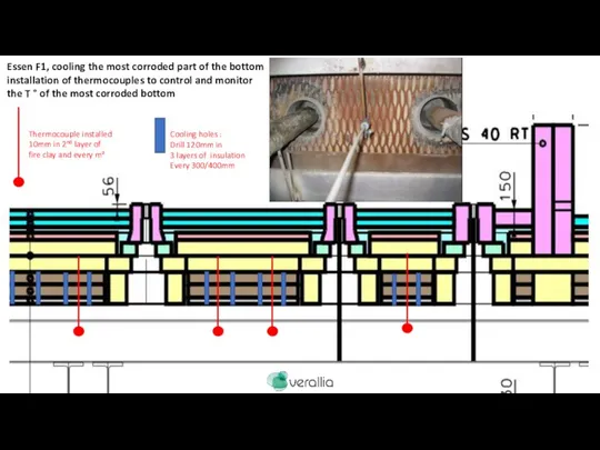
Thermocouple installed
10mm in 2nd layer of
fire clay and every
Thermocouple installed
10mm in 2nd layer of
fire clay and every
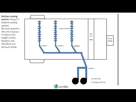
Bottom cooling system: Zorya F2 bottom cooling system,
the best system is
Bottom cooling system: Zorya F2 bottom cooling system,
the best system is
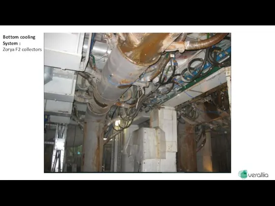
Bottom cooling
System :
Zorya F2 collectors
Bottom cooling
System :
Zorya F2 collectors
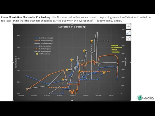
Essen F1 volution Electrodes T° / Pushing : the first conclusion
Essen F1 volution Electrodes T° / Pushing : the first conclusion
Incidents: AZS leack
If the power is not stopped immediatly, the
Incidents: AZS leack
If the power is not stopped immediatly, the
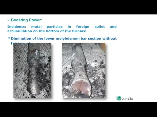
Incidents: metal particles in foreign cullet and accumulation on the bottom
Incidents: metal particles in foreign cullet and accumulation on the bottom
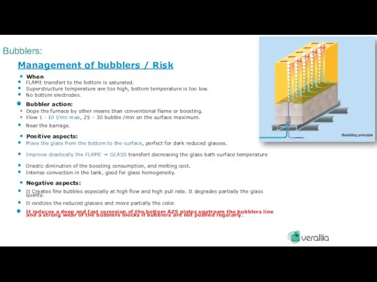
Bubblers:
Management of bubblers / Risk
When
FLAME transfert to the bottom is
Bubblers:
Management of bubblers / Risk
When
FLAME transfert to the bottom is
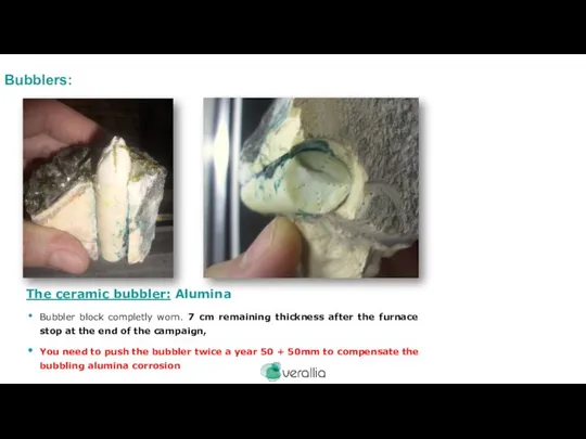
The ceramic bubbler: Alumina
Bubbler block completly worn. 7 cm remaining thickness
The ceramic bubbler: Alumina
Bubbler block completly worn. 7 cm remaining thickness
The operation parameters necessary for a good steering: At stable pull.
Which
The operation parameters necessary for a good steering: At stable pull.
Which
The operation parameters necessary for a good steering: At stable pull.
Which
The operation parameters necessary for a good steering: At stable pull.
Which
Regenerator Checker Maintenance:
1 – Never leave the thickness of sulfates deposites
Regenerator Checker Maintenance:
1 – Never leave the thickness of sulfates deposites
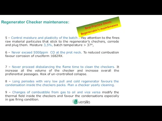
5 – Control moisture and plasticity of the batch . Pay
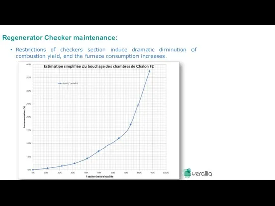
Restrictions of checkers section induce dramatic diminution of combustion yield, end
Restrictions of checkers section induce dramatic diminution of combustion yield, end
 Остров Олимпия
 AM_21
AM_21 Основы операционных систем. Лекция 11
 Verkhiy_Tagil
 Мир-ответ экстремизму
 Закон развития
 Ядерные методы анализа
 ДЭГ АВ1 для ЖН 30 сек
 ОАО Единая электронная торговая площадка
 Классификация многоэтажной жилой недвижимости
 Графические шаблоны
 Оптимизация СЭС на стадии проектирования
 Оборудование транспорта АТУ системой мониторинга транспорта
 Мы внуки страны, победившей фашизм
 Профессия Автомеханик
 20120503_skoraya_pomoshch_samomu_sebe_pri_podgotovkae_k_ege
 Пермский ДСК - сегодня
 Пост обо мне
 Светильники
 Микрорайон Соловьиная роща. Новый квартал
 Мои первые друзья
 20 лет спустя. Фотоальбом
 Повышение у детей уверенности в себе
 Повязка на голову
 Оформление страниц авторской книги
 Что нового почитать в библиотеке
 Год памяти и славы
 Domashnee_zadanie_Belarus_3_dlya_FGD_2