- SVC Manual 0727

Содержание
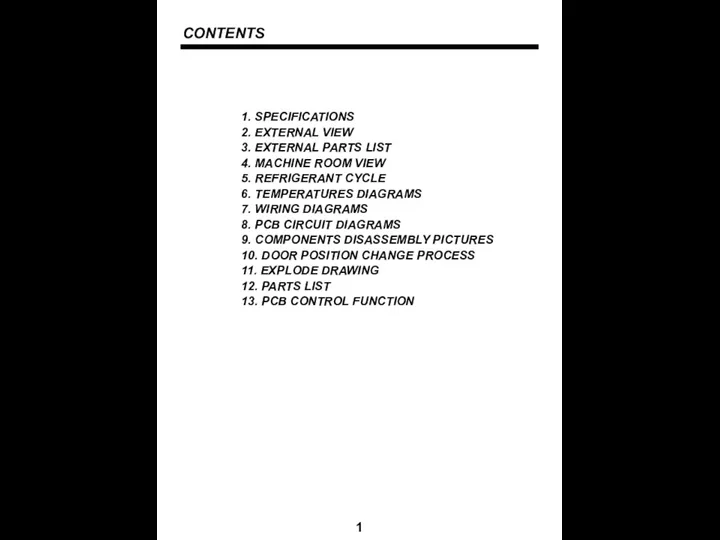
- 2. CONTENTS 1. SPECIFICATIONS 2. EXTERNAL VIEW 3. EXTERNAL PARTS LIST 4. MACHINE ROOM VIEW 5. REFRIGERANT
- 3. 1. SPECIFICATIONS 2 1.2. Types of the approved safety standards
- 4. 2. EXTERNAL VIEW 3 1 3 2 5 6 8 7 7 8 9 10 12
- 5. 3. EXTERAL PART LIST 4 1. Shelves (3EA) 2. Knob control (FR-415W/S ONLY) 3. Multi duct
- 6. 4. MACHINE ROOM VIEW 5
- 7. 5. REFRIGERANT CYCLE 6 COMRESSOR
- 8. 6. TEMPERATURES DIAGRAM 7
- 9. 7. WIRING DIAGRAMS 8 7.1. FR-417W/S
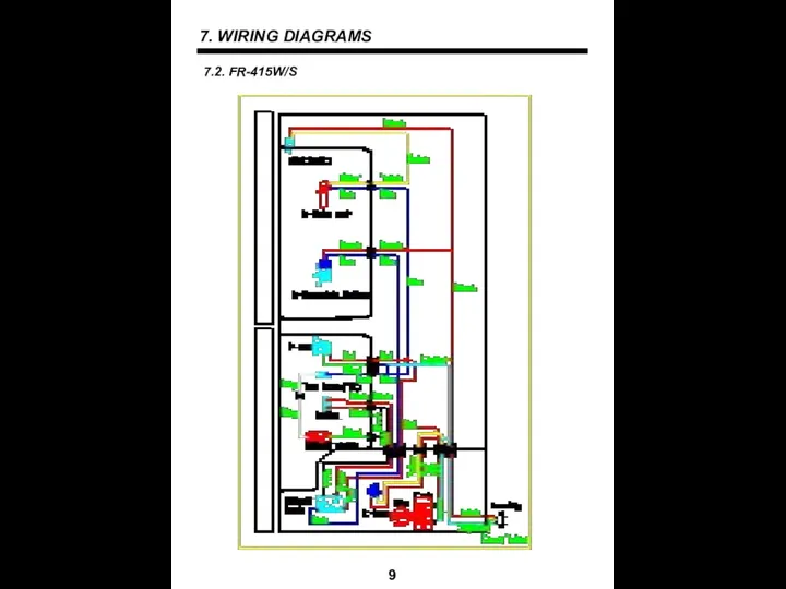
- 10. 7. WIRING DIAGRAMS 9 7.2. FR-415W/S
- 11. 8. PCB CIRCUIT DIAGRAMS 10
- 12. 9. COMPONENTS DISASSEMBLY PICTURES 11 1. FRONT PCB (FR-417W/S only) - Input a cutter sleeve between
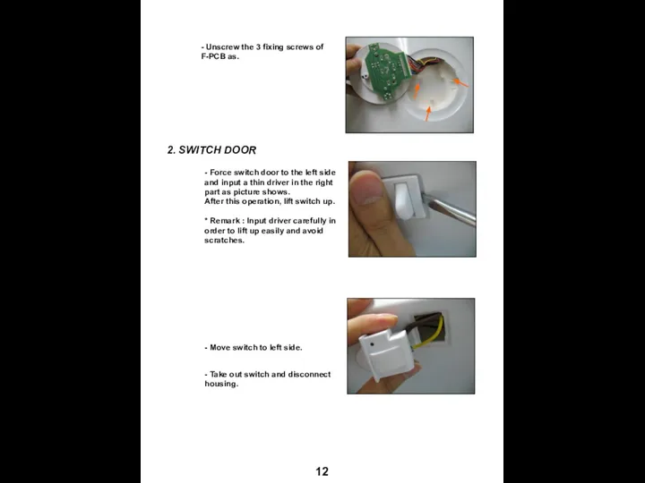
- 13. 12 2. SWITCH DOOR - Unscrew the 3 fixing screws of F-PCB as. - Force switch
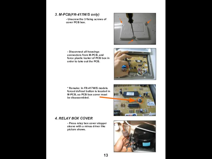
- 14. 13 4. RELAY BOX COVER - Unscrew the 3 fixing screws of cover PCB box. -
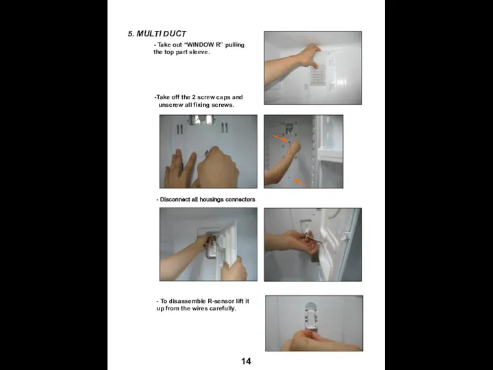
- 15. 14 - Take out “WINDOW R” pulling the top part sleeve. Take off the 2 screw
- 16. 15 - Unscrew the left fixing screw for disassembly “LOUVER F AS” and “LINER”. - Disconnect
- 17. 16 - When louvers are disassembled is very important check Knob F louver position. Default position
- 18. 10. DOOR POSITION CHANGE PROCESS 17
- 19. 18
- 20. 11. EXPLODE DRAWING 19
- 21. 11. EXPLODE DRAWING 20
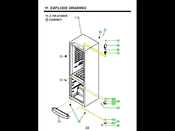
- 22. 11. EXPLODE DRAWING 21
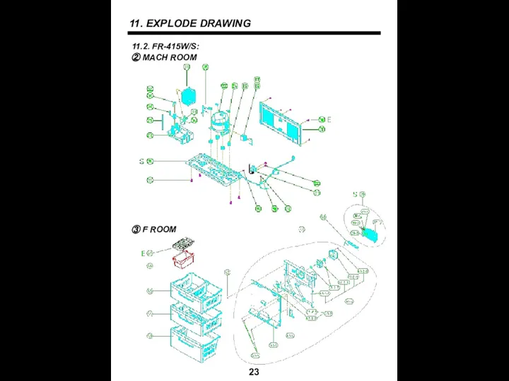
- 23. 11. EXPLODE DRAWING 22
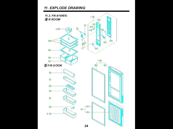
- 24. 11. EXPLODE DRAWING 23
- 25. 11. EXPLODE DRAWING 24
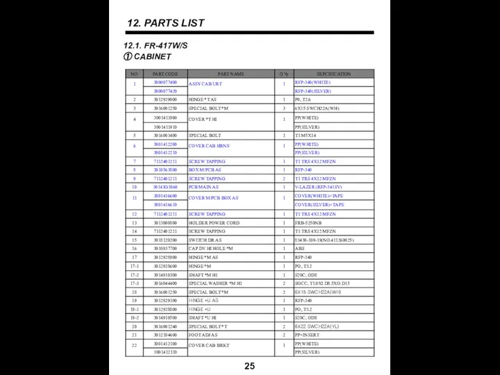
- 26. 12. PARTS LIST 25 12.1. FR-417W/S ① CABINET
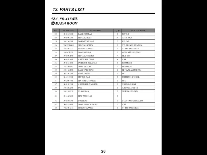
- 27. 12. PARTS LIST 26 12.1. FR-417W/S ② MACH ROOM
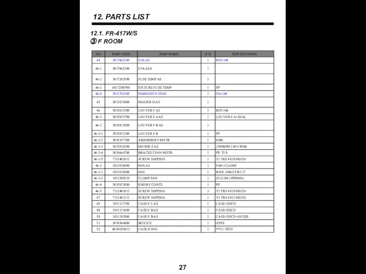
- 28. 12. PARTS LIST 27 12.1. FR-417W/S ③ F ROOM
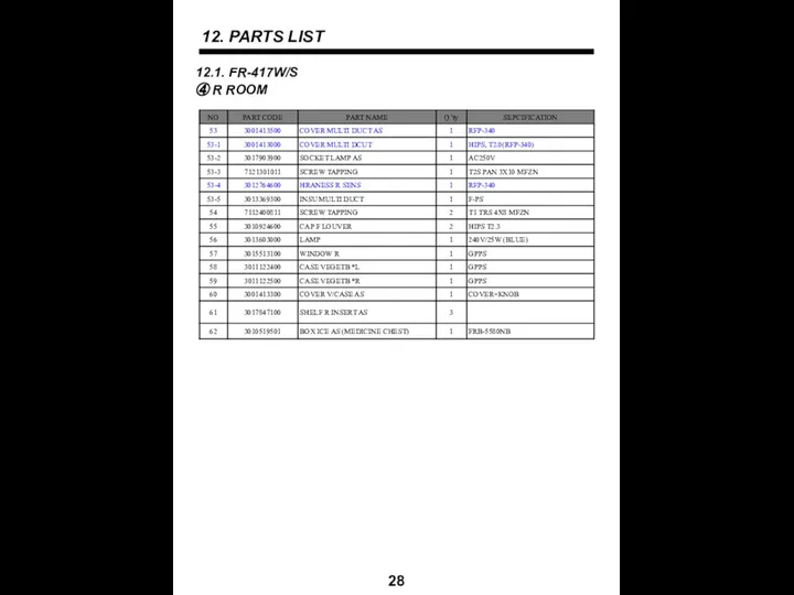
- 29. 12. PARTS LIST 28 12.1. FR-417W/S ④ R ROOM
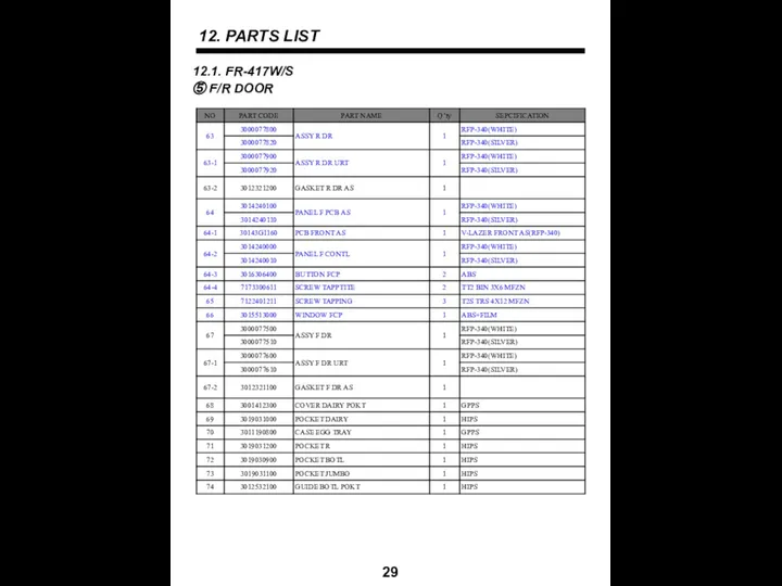
- 30. 12. PARTS LIST 29 12.1. FR-417W/S ⑤ F/R DOOR
- 31. 12. PARTS LIST 30 12.2. FR-415W/S ① CABINET
- 32. 12. PARTS LIST 31 12.2. FR-415W/S ② MACH ROOM
- 33. 12. PARTS LIST 32 12.2. FR-415W/S ③ F ROOM
- 34. 12. PARTS LIST 33 12.2. FR-415W/S ④ R ROOM
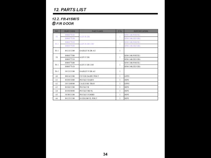
- 35. 12. PARTS LIST 34 12.2. FR-415W/S ⑤ F/R DOOR
- 36. 13. PCB CONTROL FUNCTION 35 FR-417W, FR-417S
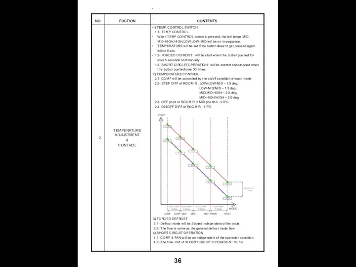
- 37. 36
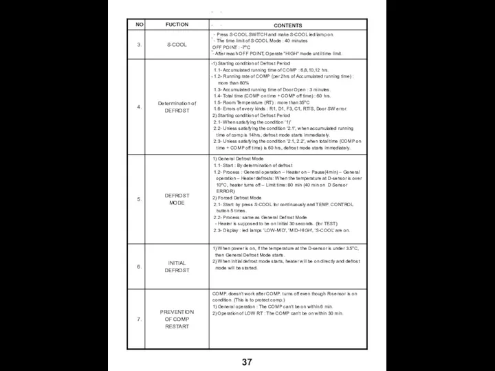
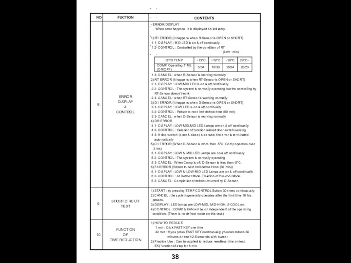
- 38. 37
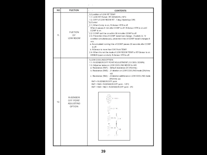
- 39. 38
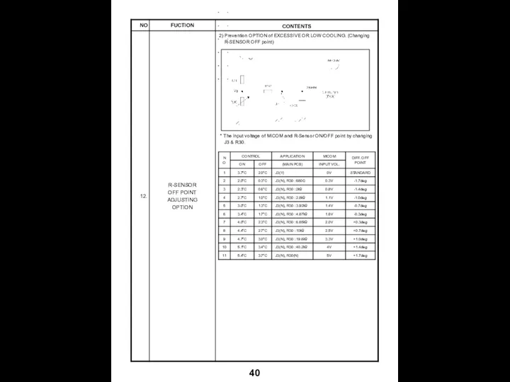
- 40. 39
- 41. 40
- 43. Скачать презентацию
CONTENTS
1. SPECIFICATIONS
2. EXTERNAL VIEW
3. EXTERNAL PARTS LIST
4. MACHINE ROOM VIEW
5. REFRIGERANT
CONTENTS
1. SPECIFICATIONS
2. EXTERNAL VIEW
3. EXTERNAL PARTS LIST
4. MACHINE ROOM VIEW
5. REFRIGERANT
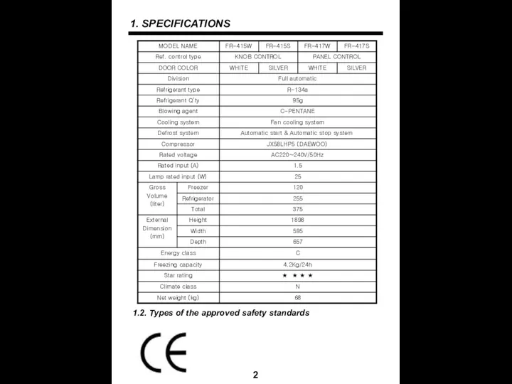
1. SPECIFICATIONS
2
1.2. Types of the approved safety standards
1. SPECIFICATIONS
2
1.2. Types of the approved safety standards
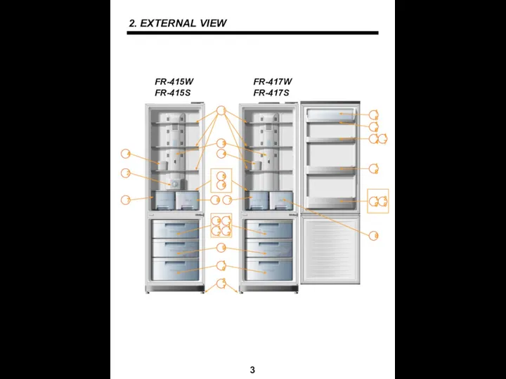
2. EXTERNAL VIEW
3
1
3
2
5
6
8
7
7
8
9
10
12
13
14
15
16
17
18
19
20
21
4
4
9
11
FR-415W
FR-415S
FR-417W
FR-417S
2. EXTERNAL VIEW
3
1
3
2
5
6
8
7
7
8
9
10
12
13
14
15
16
17
18
19
20
21
4
4
9
11
FR-415W
FR-415S
FR-417W
FR-417S
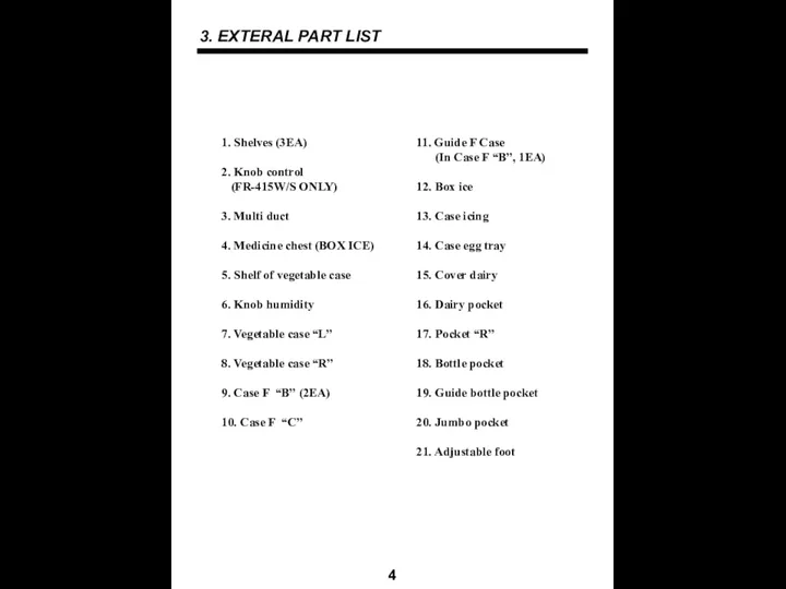
3. EXTERAL PART LIST
4
1. Shelves (3EA)
2. Knob control
(FR-415W/S ONLY)
3. Multi
3. EXTERAL PART LIST
4
1. Shelves (3EA)
2. Knob control
(FR-415W/S ONLY)
3. Multi
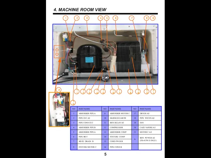
4. MACHINE ROOM VIEW
5
4. MACHINE ROOM VIEW
5
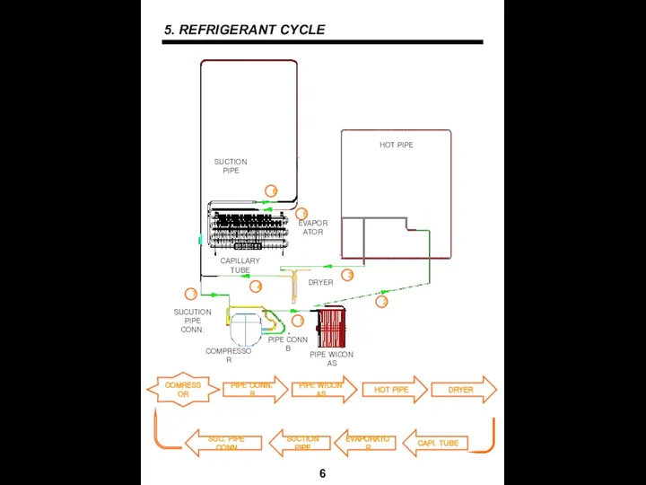
5. REFRIGERANT CYCLE
6
COMRESSOR
5. REFRIGERANT CYCLE
6
COMRESSOR
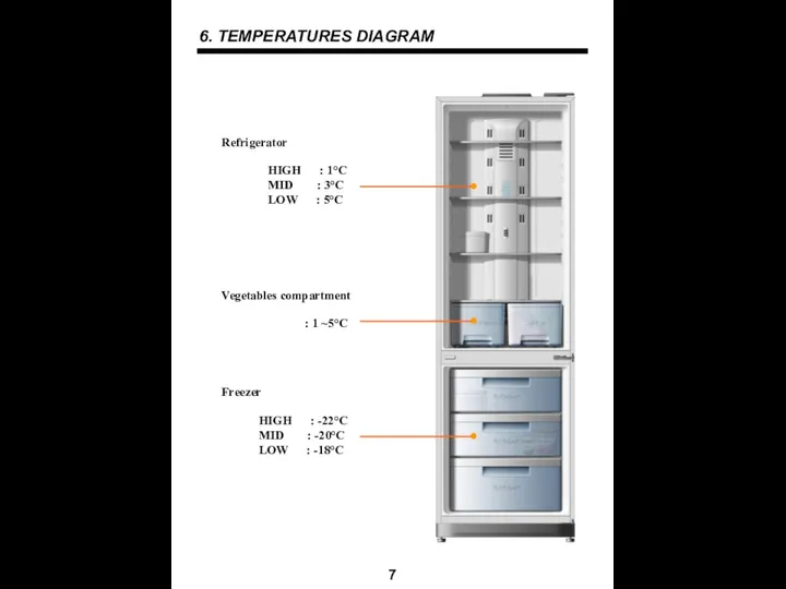
6. TEMPERATURES DIAGRAM
7
6. TEMPERATURES DIAGRAM
7
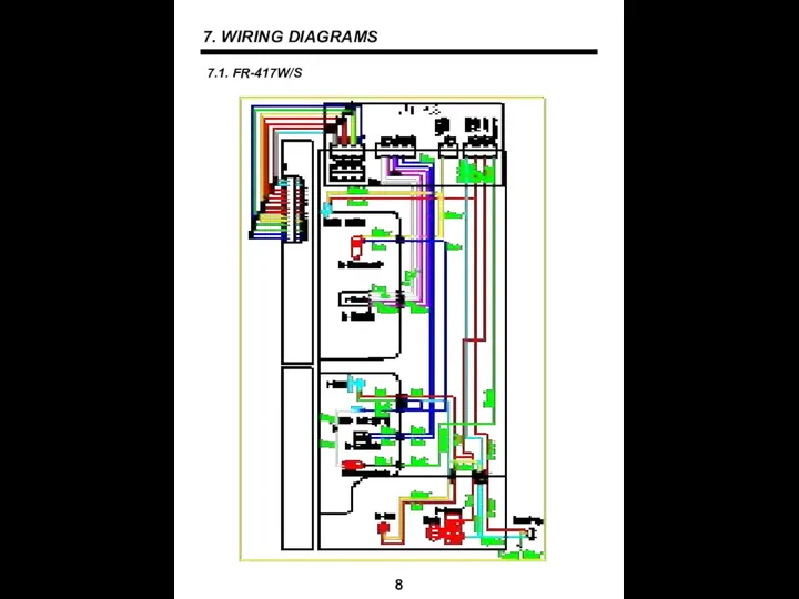
7. WIRING DIAGRAMS
8
7.1. FR-417W/S
7. WIRING DIAGRAMS
8
7.1. FR-417W/S
7. WIRING DIAGRAMS
9
7.2. FR-415W/S
7. WIRING DIAGRAMS
9
7.2. FR-415W/S
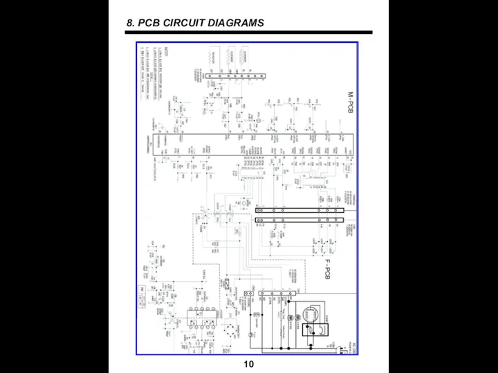
8. PCB CIRCUIT DIAGRAMS
10
8. PCB CIRCUIT DIAGRAMS
10

9. COMPONENTS DISASSEMBLY PICTURES
11
1. FRONT PCB (FR-417W/S only)
- Input a cutter
9. COMPONENTS DISASSEMBLY PICTURES
11
1. FRONT PCB (FR-417W/S only)
- Input a cutter
12
2. SWITCH DOOR
- Unscrew the 3 fixing screws of F-PCB as.
-
12
2. SWITCH DOOR
- Unscrew the 3 fixing screws of F-PCB as.
-
13
4. RELAY BOX COVER
- Unscrew the 3 fixing screws of cover
13
4. RELAY BOX COVER
- Unscrew the 3 fixing screws of cover
14
- Take out “WINDOW R” pulling the top part sleeve.
Take off
14
- Take out “WINDOW R” pulling the top part sleeve.
Take off
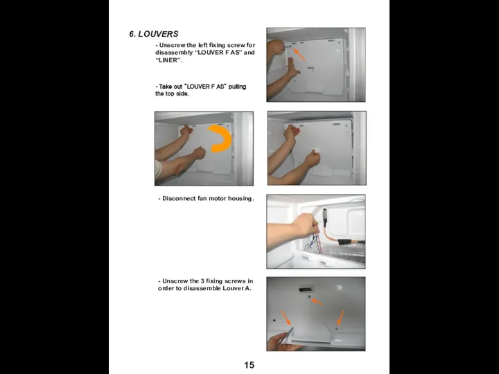
15
- Unscrew the left fixing screw for disassembly “LOUVER F AS”
15
- Unscrew the left fixing screw for disassembly “LOUVER F AS”
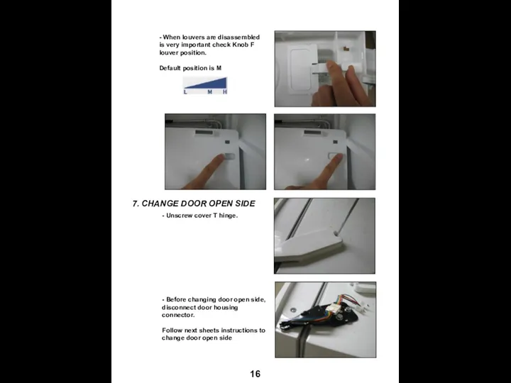
16
- When louvers are disassembled is very important check Knob F
16
- When louvers are disassembled is very important check Knob F
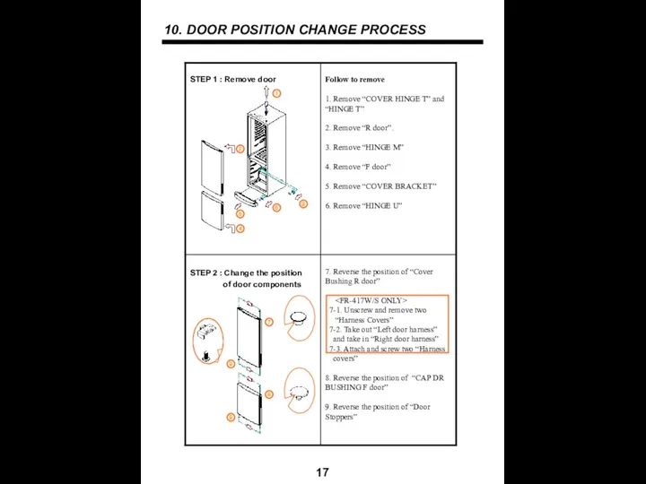
10. DOOR POSITION CHANGE PROCESS
17
10. DOOR POSITION CHANGE PROCESS
17
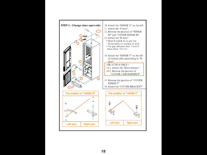
18
18
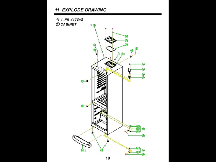
11. EXPLODE DRAWING
19
11. EXPLODE DRAWING
19
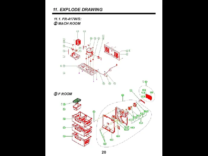
11. EXPLODE DRAWING
20
11. EXPLODE DRAWING
20
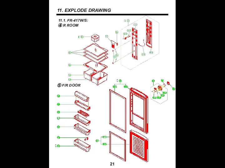
11. EXPLODE DRAWING
21
11. EXPLODE DRAWING
21
11. EXPLODE DRAWING
22
11. EXPLODE DRAWING
22
11. EXPLODE DRAWING
23
11. EXPLODE DRAWING
23
11. EXPLODE DRAWING
24
11. EXPLODE DRAWING
24
12. PARTS LIST
25
12.1. FR-417W/S
① CABINET
12. PARTS LIST
25
12.1. FR-417W/S
① CABINET
12. PARTS LIST
26
12.1. FR-417W/S
② MACH ROOM
12. PARTS LIST
26
12.1. FR-417W/S
② MACH ROOM
12. PARTS LIST
27
12.1. FR-417W/S
③ F ROOM
12. PARTS LIST
27
12.1. FR-417W/S
③ F ROOM
12. PARTS LIST
28
12.1. FR-417W/S
④ R ROOM
12. PARTS LIST
28
12.1. FR-417W/S
④ R ROOM
12. PARTS LIST
29
12.1. FR-417W/S
⑤ F/R DOOR
12. PARTS LIST
29
12.1. FR-417W/S
⑤ F/R DOOR
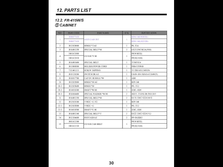
12. PARTS LIST
30
12.2. FR-415W/S
① CABINET
12. PARTS LIST
30
12.2. FR-415W/S
① CABINET
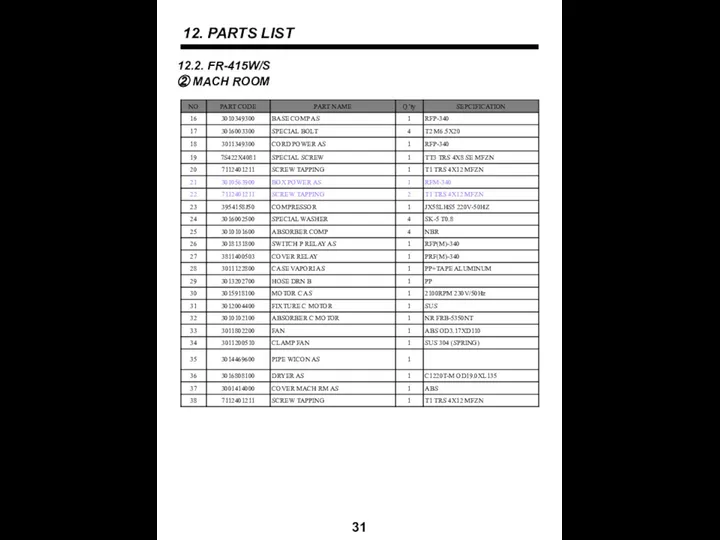
12. PARTS LIST
31
12.2. FR-415W/S
② MACH ROOM
12. PARTS LIST
31
12.2. FR-415W/S
② MACH ROOM
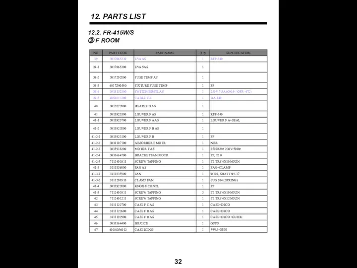
12. PARTS LIST
32
12.2. FR-415W/S
③ F ROOM
12. PARTS LIST
32
12.2. FR-415W/S
③ F ROOM
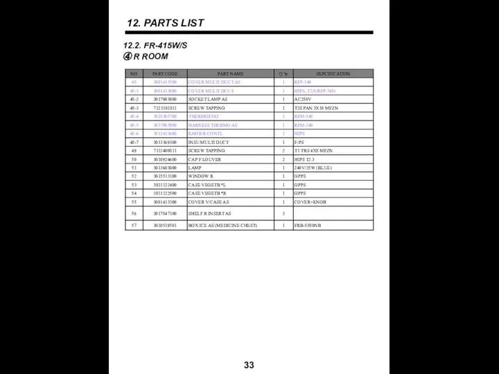
12. PARTS LIST
33
12.2. FR-415W/S
④ R ROOM
12. PARTS LIST
33
12.2. FR-415W/S
④ R ROOM
12. PARTS LIST
34
12.2. FR-415W/S
⑤ F/R DOOR
12. PARTS LIST
34
12.2. FR-415W/S
⑤ F/R DOOR
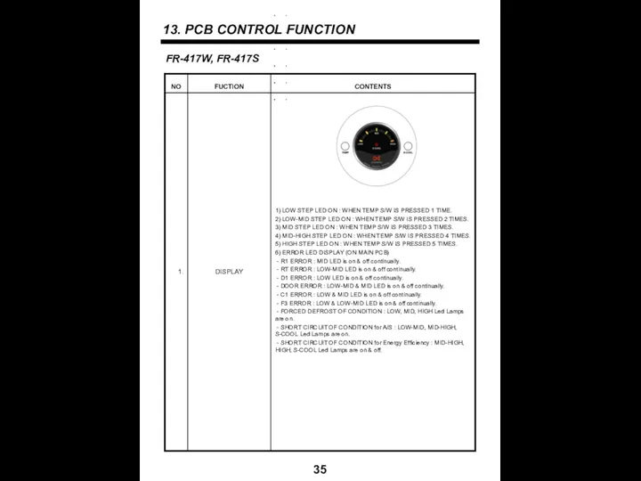
13. PCB CONTROL FUNCTION
35
FR-417W, FR-417S
13. PCB CONTROL FUNCTION
35
FR-417W, FR-417S
36
36
37
37
38
38
39
39
40
40
 Газотурбинные установки замкнутого цикла
 Продукция химической и связанных с ней отраслей промышленности
 Православный храм
 Музыкальная квест – игра Потерянная скрипка
 Развитие науки
 Praktika_V2
 Проект реконструкции ТЭЦ с установкой паровой турбины
 NP_BURG_Pt Situ BSS janvier 2021
 Разбор подхода решения задач на Пластинку
 Diapozitivul. Suntem fiii și fiicele lui dumnezeu
 paporotniki
 Тормыш ул озын су кебек Ага да ага икән
 Православная молитва
 Comment on Arm Main
 20161012_den_pobedy
 Центральный процессор Intel поколения Core i3, Core i5 и Core i7
 Лекция 1 (2)
 Пропуск судна через шлюз
 Почта деда Мороза. С
 День святых жён - мироносиц
 Русалка
 OTChET (1)
 Лопастной бур
 Вебинар - здоровое питание и бизнес
 Авиационные аварийные радиомаяки системы КОСПАС-САРСАТ. Проблемы и пути их решения
 Моделирование юбок на основе юбки-колокол
 General stone liner info
 Символика Кузбасса