- Теоретический материал к сервисному тренингу

Содержание
- 2. System Overview-Appearance LCD Monitor Touch Screen Probe Holder Main Control Panel Chamber for B/W video printer
- 3. System Overview-Appearance Monitor Support Arm Color Video Printer Table Hanger IO Panel
- 4. System Overview Difference between DC-8(XP) ,DC-8(WIN7) and DC-8EXP
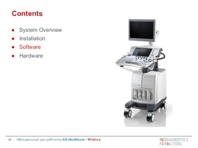
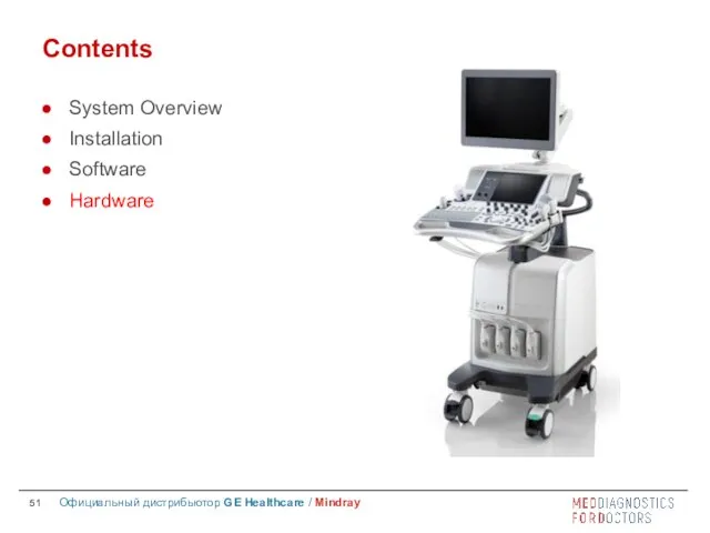
- 5. Contents System Overview Installation Software Hardware
- 6. Installation Power Supply Requirement Environmental conditions Unpacking Peripheral devices
- 7. Voltage 100-127V~ or 220-240V~ Frequency 50/60 Hz Power consumption 800VA Note: If the power supply is
- 8. Storage and Transportation Environment Ambient temperature: -20℃ ~ 55℃ Relative humidity: 30% ~95% (no condensation) Atmospheric
- 9. Operating Environment Ambient temperature for different parts: 0℃ ~ 40℃ for unit and probes( except 4D
- 10. Requirements for Space Place the system with accessories in a proper position so that users can
- 11. Requirements for Position Do not install the system in the following positions: Heat source High-humidity Flammable
- 12. Unpacking Installation—Unpacking Before unpacking, please confirm if package is OK, if any damage on package, please
- 13. Installation—Unpacking Dimension: 1355~1800mm(H) ×930mm(D) ×585mm(W) Net weight: about 110 Kg Gross weight: about 168Kg Package size:
- 14. Unpacking Installation—Unpacking Cut off belts Cut off two belts Accessory box Accessory box
- 15. Installation—Unpacking Unlock two belts Unlock two belts
- 16. Installation—Unpacking Unpacking Front board
- 17. Installation—Unpacking Unpacking Frontal baffle board
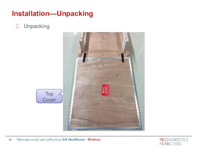
- 18. Installation—Unpacking Unpacking Top Cover
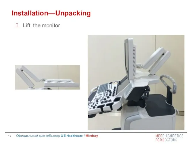
- 19. Installation—Unpacking Lift the monitor
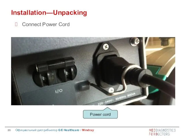
- 20. Installation—Unpacking Connect Power Cord
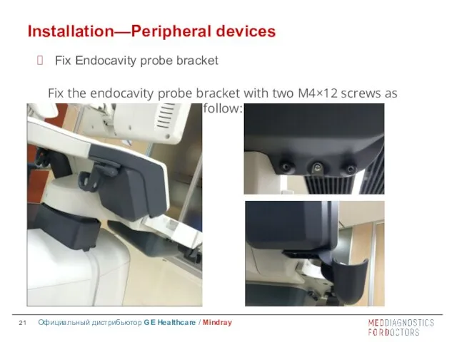
- 21. Installation—Peripheral devices Fix Endocavity probe bracket Fix the endocavity probe bracket with two M4×12 screws as
- 22. Installation—Peripheral devices Connect probe Before connecting or disconnecting probe, we should freeze the image or power
- 23. Installation—Peripheral devices Connect footswitch
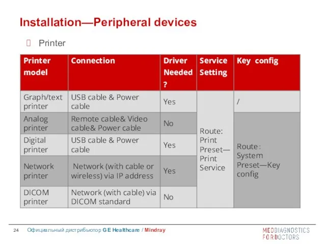
- 24. Installation—Peripheral devices Printer
- 25. Contents System Overview Installation Software Hardware
- 26. Software iStation Setup Maintenance Make recovery Specific software
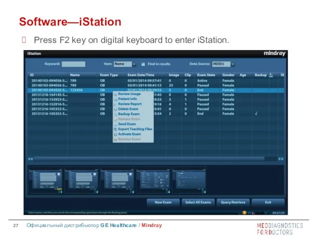
- 27. Software—iStation Press F2 key on digital keyboard to enter iStation.
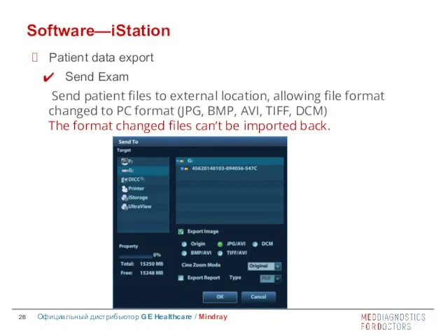
- 28. Software—iStation Patient data export Send Exam Send patient files to external location, allowing file format changed
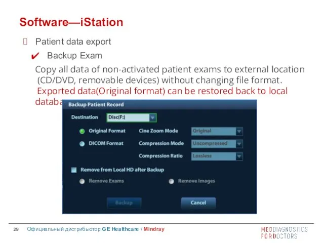
- 29. Software—iStation Patient data export Backup Exam Copy all data of non-activated patient exams to external location
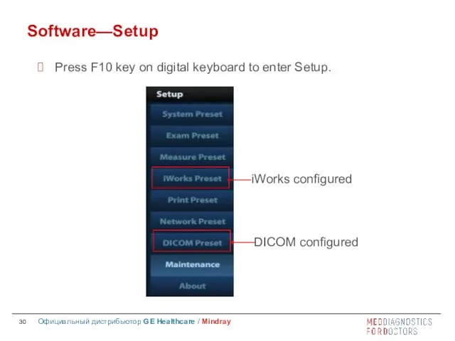
- 30. Software—Setup Press F10 key on digital keyboard to enter Setup.
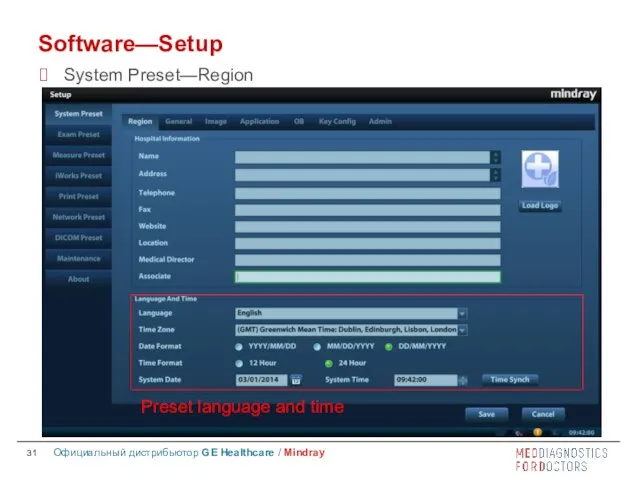
- 31. Software—Setup Preset language and time System Preset—Region
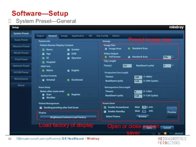
- 32. Software—Setup System Preset—General
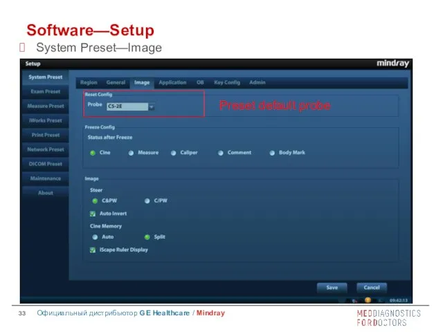
- 33. Software—Setup System Preset—lmage
- 34. Software—Setup System Preset—Key Config
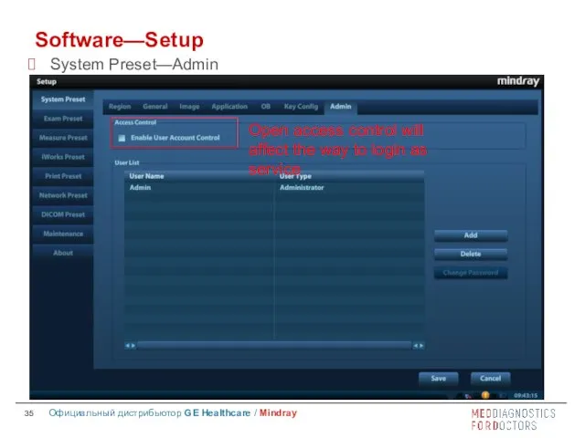
- 35. Software—Setup System Preset—Admin
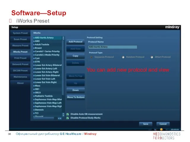
- 36. Software—Setup iWorks Preset
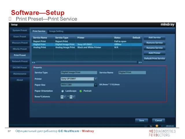
- 37. Software—Setup Print Preset—Print Service
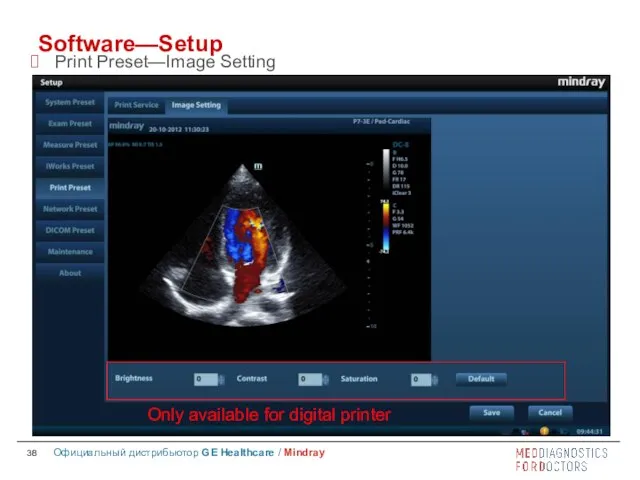
- 38. Software—Setup Print Preset—Image Setting
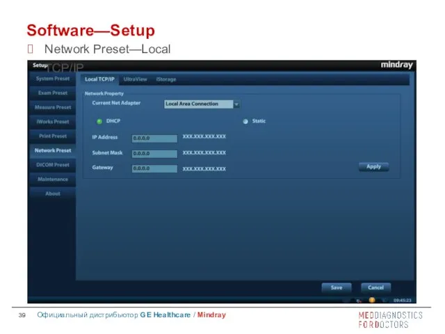
- 39. Software—Setup Network Preset—Local TCP/IP
- 40. Software—Setup DICOM Preset
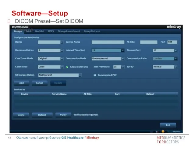
- 41. Software—Setup DICOM Preset—Set DICOM Service
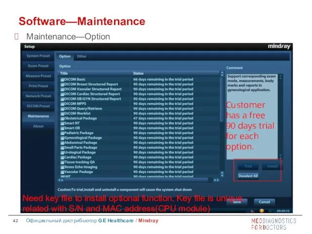
- 42. Software—Maintenance Maintenance—Option
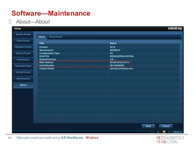
- 43. Software—Maintenance About—About
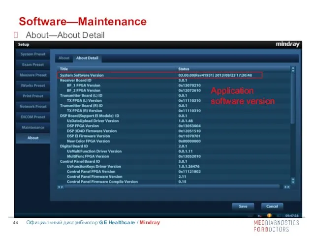
- 44. Software—Maintenance About—About Detail
- 45. Login as service When Access Control is disabled: press “ctrl”+“/” to pop up the Login dialogue
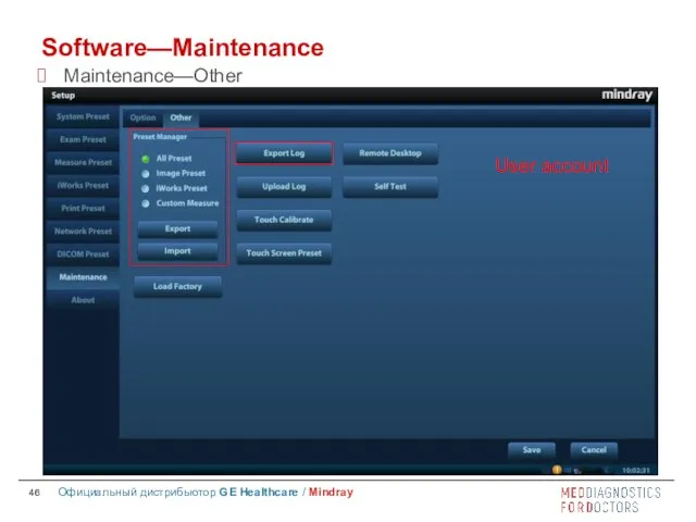
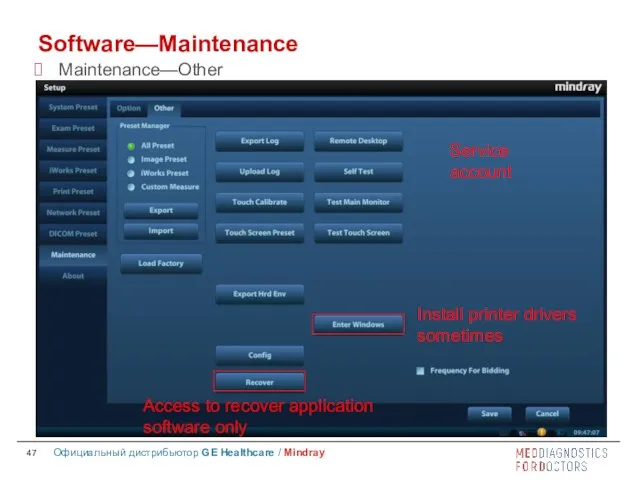
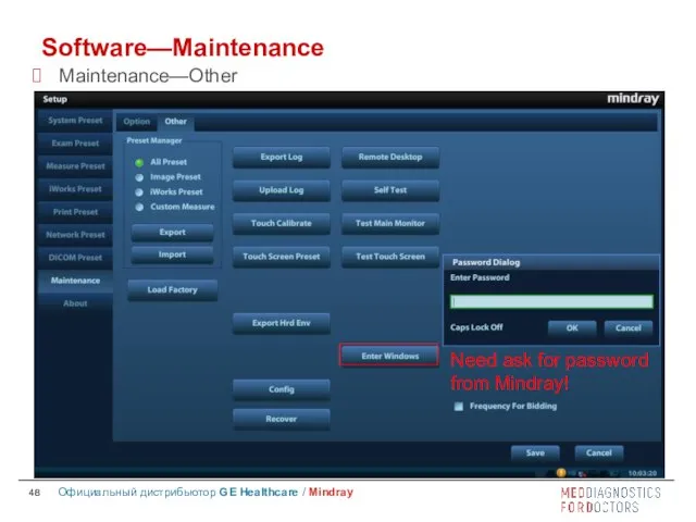
- 46. Software—Maintenance Maintenance—Other
- 47. Software—Maintenance Maintenance—Other
- 48. Software—Maintenance Maintenance—Other
- 49. Recovery types Recover OS and application software together. Recover application software only. Preparations Get a safe
- 50. Recovery procedure Step One - Data Backup Step Two – Make the Recovery USB Flash Drive
- 51. Contents System Overview Installation Software Hardware
- 52. Hardware Exploded view Module picture and schematic diagram
- 53. Hardware —Exploded view Exploded View
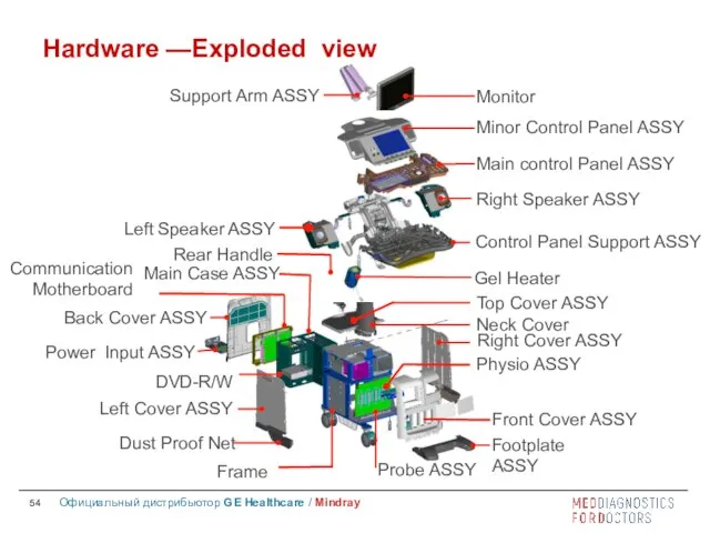
- 54. Hardware —Exploded view
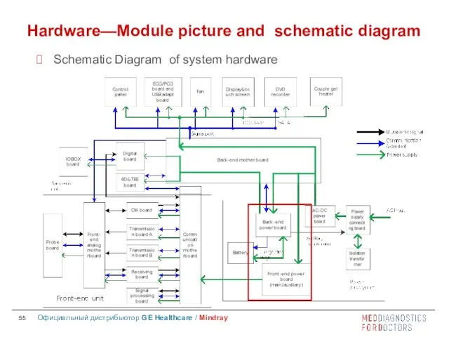
- 55. Hardware—Module picture and schematic diagram Schematic Diagram of system hardware
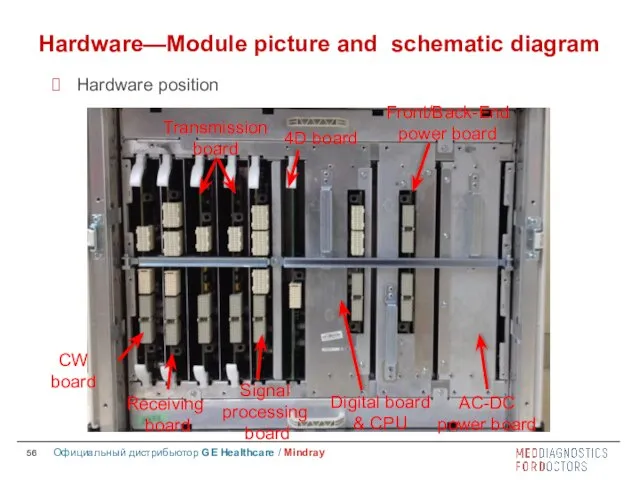
- 56. Hardware—Module picture and schematic diagram Hardware position CW board Receiving board Transmissionboard Signal processing board 4D
- 57. Support 256/192/128-element probes, 4D probes, 128/96/64-element phased array probes and TEE probes; Element switching is performed
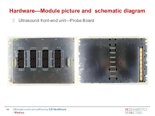
- 58. Hardware—Module picture and schematic diagram Ultrasound front-end unit—Probe Board
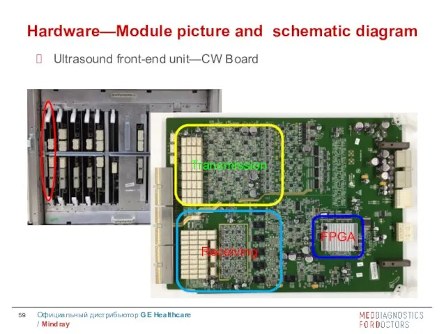
- 59. Transmission Receiving FPGA Hardware—Module picture and schematic diagram Ultrasound front-end unit—CW Board
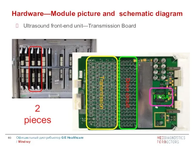
- 60. Transmission Drive circuit FPGA 2 pieces Hardware—Module picture and schematic diagram Ultrasound front-end unit—Transmission Board
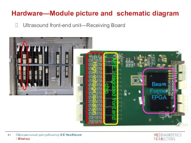
- 61. High-voltage isolation AFE integrated front end chip Beam Former FPGA Hardware—Module picture and schematic diagram Ultrasound
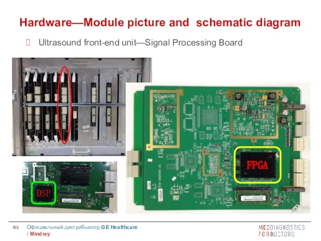
- 62. Digital signal processing for B, C, D imaging modes. The imaging data will be packed and
- 63. Hardware—Module picture and schematic diagram Ultrasound front-end unit—Signal Processing Board FPGA DSP
- 64. 4D signal cable To probe board Front-end analog mother board Hardware—Module picture and schematic diagram Ultrasound
- 65. Hardware—Module picture and schematic diagram Ultrasound front-end unit—Communication Motherboard
- 66. Standard COM-E socket; Back-end video processing, realize CPU module video output extending. DVI*2, VGA, Composite Video,
- 67. CPU module Multi-function FPGA Hardware—Module picture and schematic diagram Ultrasound back-end unit—Digital Board & CPU Module
- 68. Hardware—Module picture and schematic diagram Ultrasound back-end unit —IOBOX Board
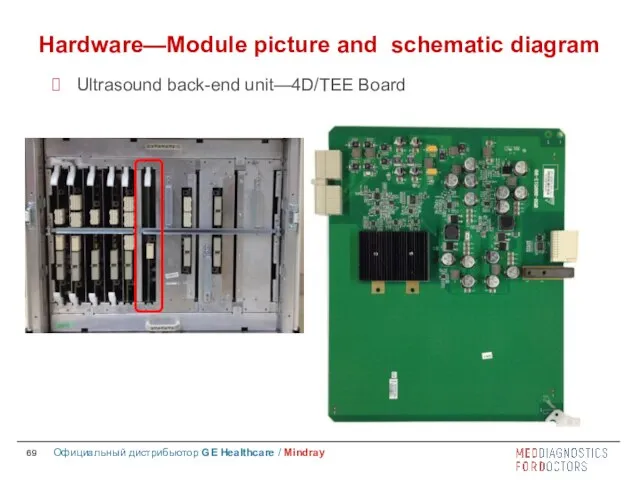
- 69. Hardware—Module picture and schematic diagram Ultrasound back-end unit—4D/TEE Board
- 70. Hardware—Module picture and schematic diagram Peripherals—Control Panel Unit
- 71. Hardware—Module picture and schematic diagram Peripherals—Control Panel Unit
- 72. Be careful when disassembling Hardware—Module picture and schematic diagram Peripherals—Main Monitor Unit (19 inch)
- 73. Be careful when disassembling Hardware—Module picture and schematic diagram Peripherals—Main Monitor Unit (21.5 inch) Cooling hole
- 74. Hardware—Module picture and schematic diagram Peripherals—Touch Screen Unit
- 75. Hardware—Module picture and schematic diagram Power Supply Unit—Power Connecting Board
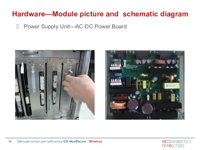
- 76. Hardware—Module picture and schematic diagram Power Supply Unit—AC-DC Power Board
- 77. Back-End Power Board Hardware—Module picture and schematic diagram Power Supply Unit—Back end Power Board
- 78. Front End Power auxiliary Board Front End Power Main Board Hardware—Module picture and schematic diagram Power
- 79. Hardware—Module picture and schematic diagram Power On Process-1
- 80. Hardware—Module picture and schematic diagram Power On Process-2
- 82. Скачать презентацию

System Overview-Appearance
LCD Monitor
Touch Screen
Probe Holder
Main Control Panel
Chamber for B/W video printer
Physio
System Overview-Appearance
LCD Monitor
Touch Screen
Probe Holder
Main Control Panel
Chamber for B/W video printer
Physio
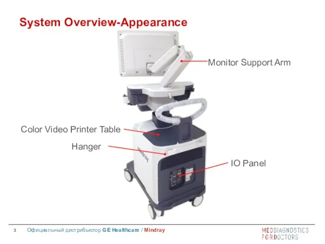
System Overview-Appearance
Monitor Support Arm
Color Video Printer Table
Hanger
IO Panel
System Overview-Appearance
Monitor Support Arm
Color Video Printer Table
Hanger
IO Panel

System Overview
Difference between DC-8(XP) ,DC-8(WIN7) and DC-8EXP
System Overview
Difference between DC-8(XP) ,DC-8(WIN7) and DC-8EXP

Contents
System Overview
Installation
Software
Hardware
Contents
System Overview
Installation
Software
Hardware

Installation
Power Supply Requirement
Environmental conditions
Unpacking
Peripheral devices
Installation
Power Supply Requirement
Environmental conditions
Unpacking
Peripheral devices
Voltage
100-127V~ or 220-240V~
Frequency
50/60 Hz
Power consumption
800VA
Note: If the power supply
Voltage
100-127V~ or 220-240V~
Frequency
50/60 Hz
Power consumption
800VA
Note: If the power supply
Storage and Transportation Environment
Ambient temperature: -20℃ ~ 55℃
Relative humidity:
Storage and Transportation Environment
Ambient temperature: -20℃ ~ 55℃
Relative humidity:

Operating Environment
Ambient temperature for different parts:
0℃ ~ 40℃ for
Operating Environment
Ambient temperature for different parts:
0℃ ~ 40℃ for
Requirements for Space
Place the system with accessories in a proper position
Requirements for Space
Place the system with accessories in a proper position

Requirements for Position
Do not install the system in the following
Requirements for Position
Do not install the system in the following

Unpacking
Installation—Unpacking
Before unpacking, please confirm if package is OK, if any
Unpacking
Installation—Unpacking
Before unpacking, please confirm if package is OK, if any
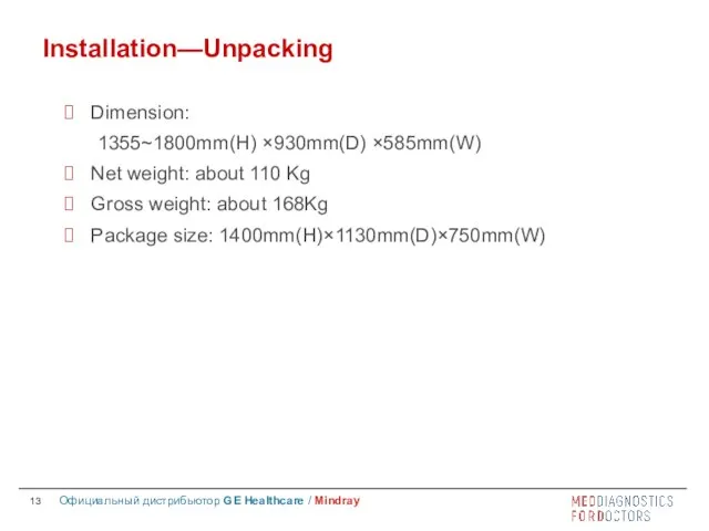
Installation—Unpacking
Dimension:
1355~1800mm(H) ×930mm(D) ×585mm(W)
Net weight: about 110 Kg
Gross weight: about 168Kg
Package
Installation—Unpacking
Dimension:
1355~1800mm(H) ×930mm(D) ×585mm(W)
Net weight: about 110 Kg
Gross weight: about 168Kg
Package
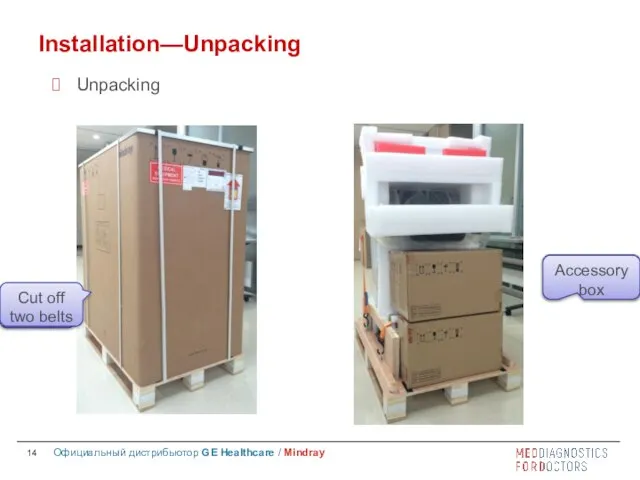
Unpacking
Installation—Unpacking
Cut off belts
Cut off
two belts
Accessory box
Accessory box
Unpacking
Installation—Unpacking
Cut off belts
Cut off
two belts
Accessory box
Accessory box

Installation—Unpacking
Unlock two belts
Unlock two belts
Installation—Unpacking
Unlock two belts
Unlock two belts
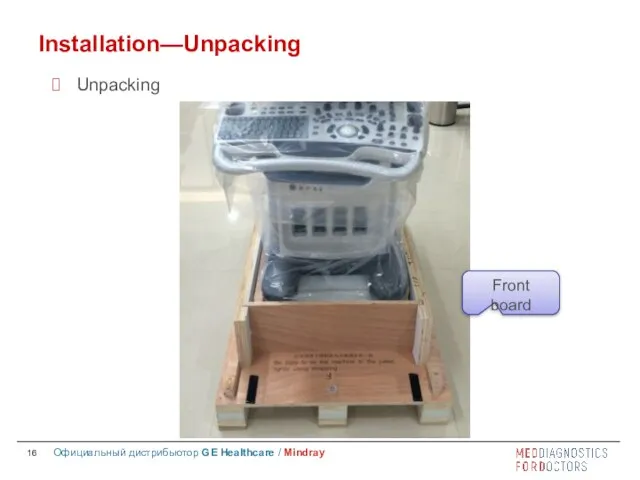
Installation—Unpacking
Unpacking
Front
board
Installation—Unpacking
Unpacking
Front
board
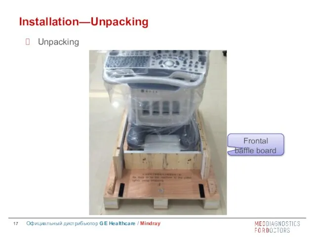
Installation—Unpacking
Unpacking
Frontal
baffle board
Installation—Unpacking
Unpacking
Frontal
baffle board
Installation—Unpacking
Unpacking
Top
Cover
Installation—Unpacking
Unpacking
Top
Cover
Installation—Unpacking
Lift the monitor
Installation—Unpacking
Lift the monitor
Installation—Unpacking
Connect Power Cord
Installation—Unpacking
Connect Power Cord
Installation—Peripheral devices
Fix Endocavity probe bracket
Fix the endocavity probe bracket with
Installation—Peripheral devices
Fix Endocavity probe bracket
Fix the endocavity probe bracket with

Installation—Peripheral devices
Connect probe
Before connecting or disconnecting probe, we should freeze the
Installation—Peripheral devices
Connect probe
Before connecting or disconnecting probe, we should freeze the

Installation—Peripheral devices
Connect footswitch
Installation—Peripheral devices
Connect footswitch
Installation—Peripheral devices
Printer
Installation—Peripheral devices
Printer
Contents
System Overview
Installation
Software
Hardware
Contents
System Overview
Installation
Software
Hardware
Software
iStation
Setup
Maintenance
Make recovery
Specific software
Software
iStation
Setup
Maintenance
Make recovery
Specific software
Software—iStation
Press F2 key on digital keyboard to enter iStation.
Software—iStation
Press F2 key on digital keyboard to enter iStation.
Software—iStation
Patient data export
Send Exam
Send patient files to external location,
Software—iStation
Patient data export
Send Exam
Send patient files to external location,
Software—iStation
Patient data export
Backup Exam
Copy all data of non-activated patient exams
Software—iStation
Patient data export
Backup Exam
Copy all data of non-activated patient exams
Software—Setup
Press F10 key on digital keyboard to enter Setup.
Software—Setup
Press F10 key on digital keyboard to enter Setup.
Software—Setup
Preset language and time
System Preset—Region
Software—Setup
Preset language and time
System Preset—Region
Software—Setup
System Preset—General
Software—Setup
System Preset—General
Software—Setup
System Preset—lmage
Software—Setup
System Preset—lmage

Software—Setup
System Preset—Key Config
Software—Setup
System Preset—Key Config
Software—Setup
System Preset—Admin
Software—Setup
System Preset—Admin
Software—Setup
iWorks Preset
Software—Setup
iWorks Preset
Software—Setup
Print Preset—Print Service
Software—Setup
Print Preset—Print Service
Software—Setup
Print Preset—Image Setting
Software—Setup
Print Preset—Image Setting
Software—Setup
Network Preset—Local TCP/IP
Software—Setup
Network Preset—Local TCP/IP

Software—Setup
DICOM Preset
Software—Setup
DICOM Preset
Software—Setup
DICOM Preset—Set DICOM Service
Software—Setup
DICOM Preset—Set DICOM Service
Software—Maintenance
Maintenance—Option
Software—Maintenance
Maintenance—Option
Software—Maintenance
About—About
Software—Maintenance
About—About
Software—Maintenance
About—About Detail
Software—Maintenance
About—About Detail
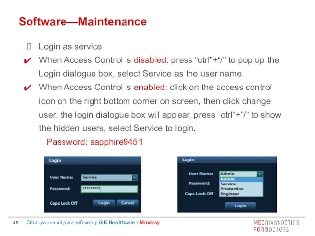
Login as service
When Access Control is disabled: press “ctrl”+“/” to pop
When Access Control is disabled: press “ctrl”+“/” to pop
Software—Maintenance
Maintenance—Other
Software—Maintenance
Maintenance—Other
Software—Maintenance
Maintenance—Other
Software—Maintenance
Maintenance—Other
Software—Maintenance
Maintenance—Other
Software—Maintenance
Maintenance—Other
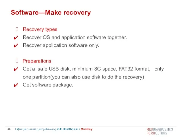
Recovery types
Recover OS and application software together.
Recover application software only.
Preparations
Get
Recovery types
Recover OS and application software together.
Recover application software only.
Preparations
Get
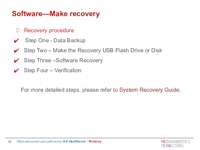
Recovery procedure
Step One - Data Backup
Step Two – Make the
Recovery procedure
Step One - Data Backup
Step Two – Make the
Contents
System Overview
Installation
Software
Hardware
Contents
System Overview
Installation
Software
Hardware

Hardware
Exploded view
Module picture and schematic diagram
Hardware
Exploded view
Module picture and schematic diagram
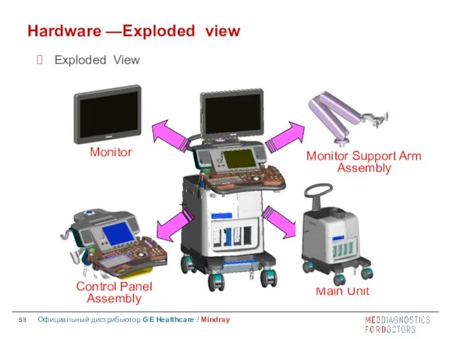
Hardware —Exploded view
Exploded View
Hardware —Exploded view
Exploded View
Hardware —Exploded view
Hardware —Exploded view
Hardware—Module picture and schematic diagram
Schematic Diagram of system hardware
Hardware—Module picture and schematic diagram
Schematic Diagram of system hardware
Hardware—Module picture and schematic diagram
Hardware position
CW board
Receiving
board
Transmissionboard
Signal
processing
board
4D
Hardware—Module picture and schematic diagram
Hardware position
CW board
Receiving
board
Transmissionboard
Signal
processing
board
4D
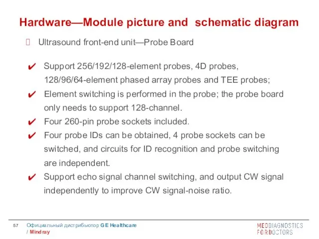
Support 256/192/128-element probes, 4D probes, 128/96/64-element phased array probes and TEE
Support 256/192/128-element probes, 4D probes, 128/96/64-element phased array probes and TEE
Hardware—Module picture and schematic diagram
Ultrasound front-end unit—Probe Board
Hardware—Module picture and schematic diagram
Ultrasound front-end unit—Probe Board
Transmission
Receiving
FPGA
Hardware—Module picture and schematic diagram
Ultrasound front-end unit—CW Board
Transmission
Receiving
FPGA
Hardware—Module picture and schematic diagram
Ultrasound front-end unit—CW Board
Transmission
Drive circuit
FPGA
2 pieces
Hardware—Module picture and schematic diagram
Ultrasound front-end unit—Transmission Board
Transmission
Drive circuit
FPGA
2 pieces
Hardware—Module picture and schematic diagram
Ultrasound front-end unit—Transmission Board
High-voltage isolation
AFE integrated front end chip
Beam Former FPGA
Hardware—Module picture and schematic
High-voltage isolation
AFE integrated front end chip
Beam Former FPGA
Hardware—Module picture and schematic
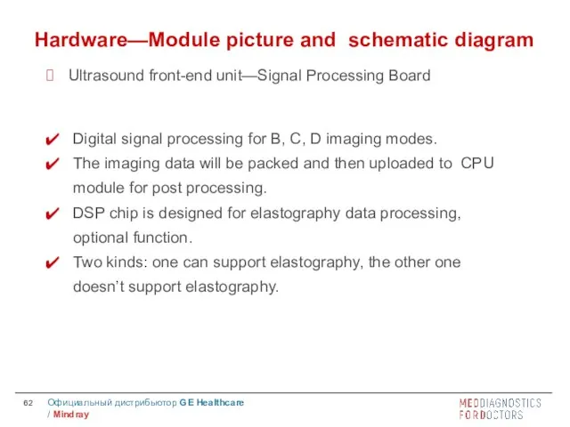
Digital signal processing for B, C, D imaging modes.
The imaging data
The imaging data
Hardware—Module picture and schematic diagram
Ultrasound front-end unit—Signal Processing Board
FPGA
DSP
Hardware—Module picture and schematic diagram
Ultrasound front-end unit—Signal Processing Board
FPGA
DSP
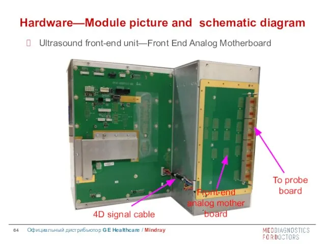
4D signal cable
To probe board
Front-end analog mother board
Hardware—Module picture and schematic
4D signal cable
To probe board
Front-end analog mother board
Hardware—Module picture and schematic

Hardware—Module picture and schematic diagram
Ultrasound front-end unit—Communication Motherboard
Hardware—Module picture and schematic diagram
Ultrasound front-end unit—Communication Motherboard
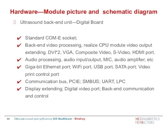
Standard COM-E socket;
Back-end video processing, realize CPU module video output extending.
Back-end video processing, realize CPU module video output extending.
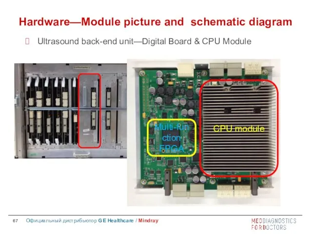
CPU module
Multi-function FPGA
Hardware—Module picture and schematic diagram
Ultrasound back-end unit—Digital Board
CPU module
Multi-function FPGA
Hardware—Module picture and schematic diagram
Ultrasound back-end unit—Digital Board
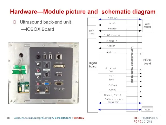
Hardware—Module picture and schematic diagram
Ultrasound back-end unit
—IOBOX Board
Hardware—Module picture and schematic diagram
Ultrasound back-end unit
—IOBOX Board
Hardware—Module picture and schematic diagram
Ultrasound back-end unit—4D/TEE Board
Hardware—Module picture and schematic diagram
Ultrasound back-end unit—4D/TEE Board
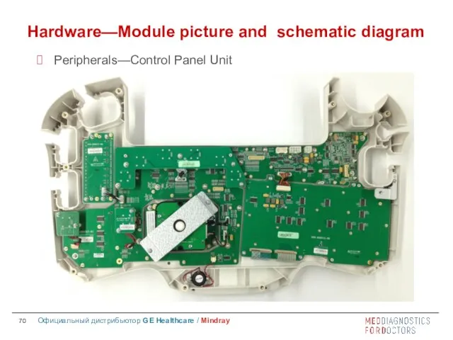
Hardware—Module picture and schematic diagram
Peripherals—Control Panel Unit
Hardware—Module picture and schematic diagram
Peripherals—Control Panel Unit
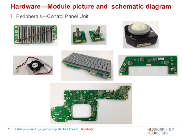
Hardware—Module picture and schematic diagram
Peripherals—Control Panel Unit
Hardware—Module picture and schematic diagram
Peripherals—Control Panel Unit
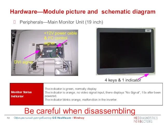
Be careful when disassembling
Hardware—Module picture and schematic diagram
Peripherals—Main Monitor Unit
Be careful when disassembling
Hardware—Module picture and schematic diagram
Peripherals—Main Monitor Unit
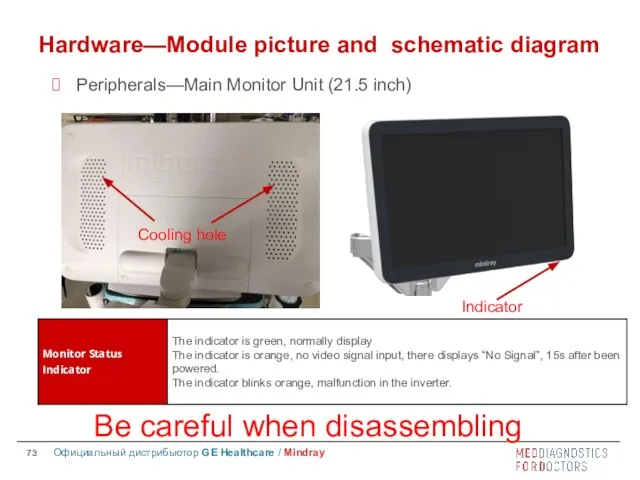
Be careful when disassembling
Hardware—Module picture and schematic diagram
Peripherals—Main Monitor Unit
Be careful when disassembling
Hardware—Module picture and schematic diagram
Peripherals—Main Monitor Unit
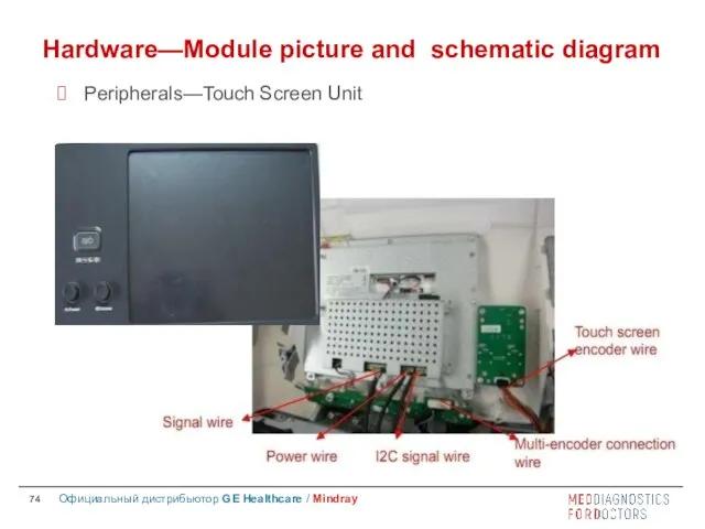
Hardware—Module picture and schematic diagram
Peripherals—Touch Screen Unit
Hardware—Module picture and schematic diagram
Peripherals—Touch Screen Unit
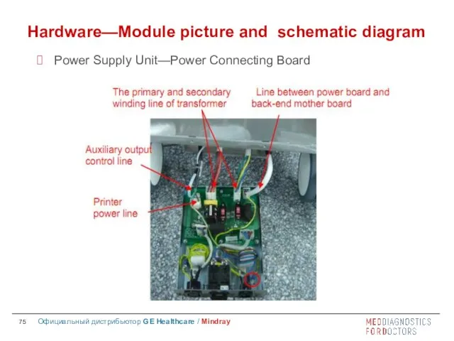
Hardware—Module picture and schematic diagram
Power Supply Unit—Power Connecting Board
Hardware—Module picture and schematic diagram
Power Supply Unit—Power Connecting Board
Hardware—Module picture and schematic diagram
Power Supply Unit—AC-DC Power Board
Hardware—Module picture and schematic diagram
Power Supply Unit—AC-DC Power Board
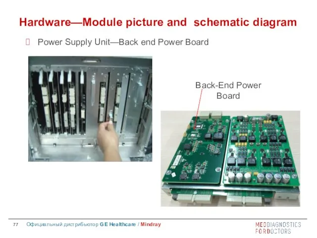
Back-End Power Board
Hardware—Module picture and schematic diagram
Power Supply Unit—Back end
Back-End Power Board
Hardware—Module picture and schematic diagram
Power Supply Unit—Back end

Front End Power auxiliary Board
Front End Power Main Board
Hardware—Module picture and
Front End Power auxiliary Board
Front End Power Main Board
Hardware—Module picture and
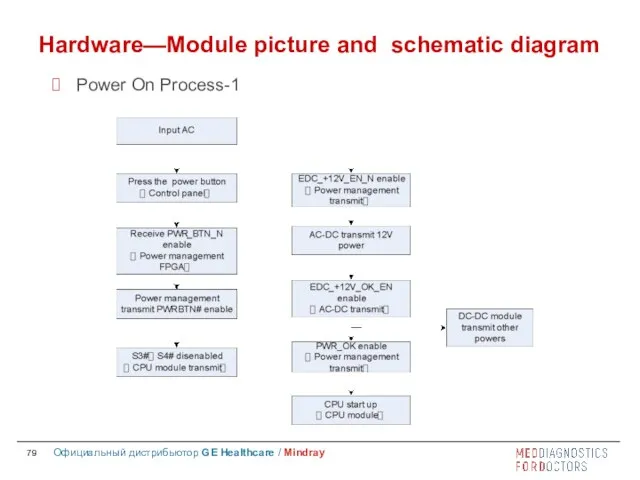
Hardware—Module picture and schematic diagram
Power On Process-1
Hardware—Module picture and schematic diagram
Power On Process-1
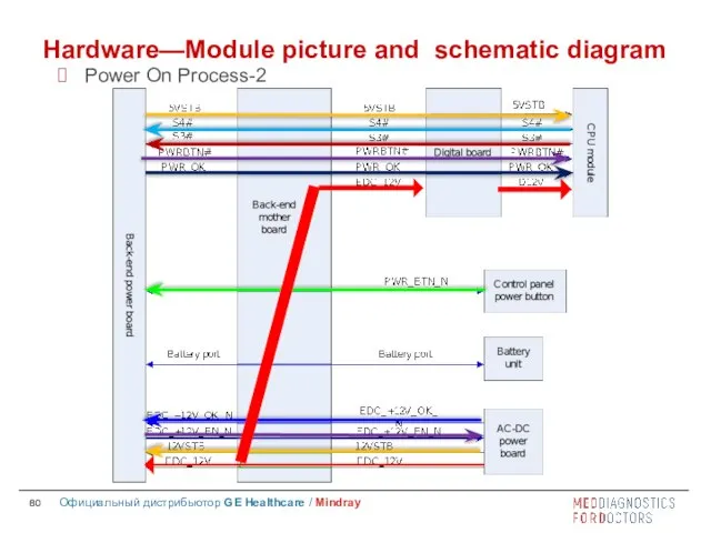
Hardware—Module picture and schematic diagram
Power On Process-2
Hardware—Module picture and schematic diagram
Power On Process-2
 Категории железных дорог
 Отрасли металлургического комплекса региона
 Устный журнал 2020
 Системы самовозбуждения генераторов серии SSED. Билет 24
 Профессии – помощники правил дорожного движения
 Классификация производств и технологий
 Биоразлагаемые зелёные растворители в качестве альтернативы традиционным растворителям
 Рекомендации для воспитателей в период адаптации детей дошкольного
 Холодное сердце
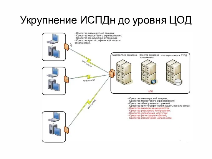 Укрупнение ИСПДн до уровня ЦОД
 Обработка жилета
 Внутреннее устройство компьютера. Ескина Татьяна
 ПрезентацияЛР1
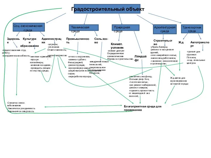 Градостроительный объект
 Книги по истории государственной безопасности России
 Организация ТО и ремонта на универсальных и специализированных постах
 Родительское собрание в форме тренинга
 My Family
 Canva в образовании
 Русские имена. Имена исконные и заимствованные, традиционные и новые, устаревшие и популярные
 Понятие о несущей способности упругодеформируемых конструкций
 Шаблон для старших направлений (2)
 год воинской славы
 Мыслить – значит жить
 Ротационная сварка трением
 Правило произведения
 Санкт-Петербургский речной Яхт-клуб. Яхта Аврора
 20121206_prestuplenie_i_nakazanie