- Training course

Содержание
- 2. Warning of Confidentiality The data and information, in its totality or partial expression, contained in this
- 3. Signature Sheet
- 4. Changes Record
- 5. Acronyms
- 6. Acronyms
- 7. Index
- 8. Index
- 9. 1 Introduction
- 10. Introduction Functions: RF signal amplification (from 15 dBm to 73 dBm): 58 dB gain. Transmits signal
- 11. Introduction Structure: Solid state amplifiers (10 units). Redundant preamplifier. Low losses splitter and combiner. Class-C output
- 12. Introduction Front view.
- 13. Introduction Back view.
- 14. Introduction Failure LEDs on the door: Power input: Ф1, Ф2, Ф3. Three phases, yellow colour. Soft
- 15. 2 Signal Path Amplification Chain Soft Failure Operation Functional Description
- 16. Signal Path RF input signal selection: TXGU 1 or TXGU 2 output. Signal division in two
- 17. Signal Path First test point to System Stability Monitor: TXG input. Second test point to System
- 18. Signal Path
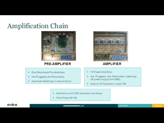
- 19. Amplification Chain Soft Failure until 20% transistors had failed. Peak Power 22 kW. Dual Redundant Pre-Amplifiers.
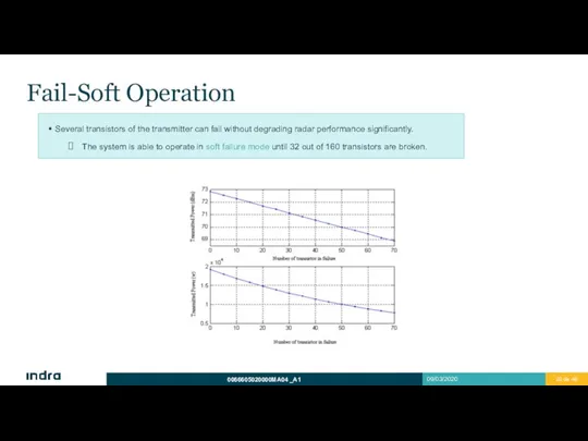
- 20. Fail-Soft Operation Several transistors of the transmitter can fail without degrading radar performance significantly. The system
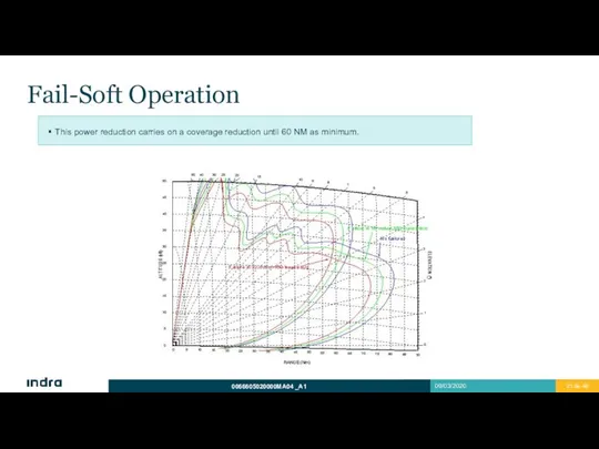
- 21. Fail-Soft Operation This power reduction carries on a coverage reduction until 60 NM as minimum.
- 22. 3 LRU List and Interfaces LRU List Power Distribution Interfaces
- 23. LRU List Transmitter Control Unit, TXCU (2). Power Amplifier, PA (10). Power Preamplifier, PRPA (2). Multivoltage
- 24. Power Distribution
- 25. Interfaces Digital
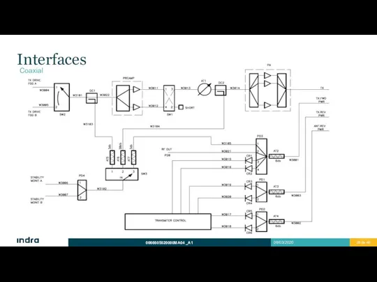
- 26. Interfaces Coaxial
- 27. 4 Subgroup Physical Description General Diagram General Description Transmitter Control Unit (TXCU) Preamplifier Panels (PRPA) Power
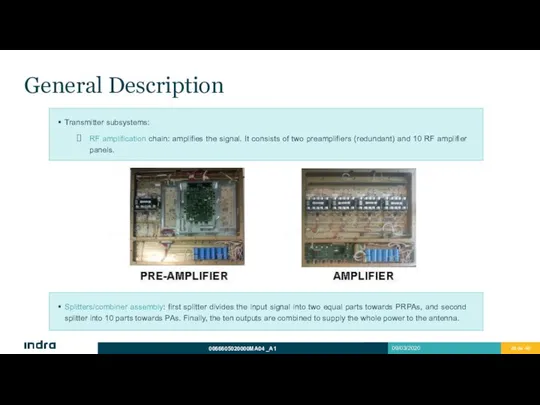
- 28. General Description Transmitter subsystems: RF amplification chain: amplifies the signal. It consists of two preamplifiers (redundant)
- 29. General Description Transmitter subsystems: Power supply assembly: consists of two groups, MVPSs and BPSs. One supplies
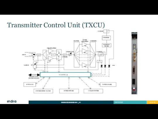
- 30. Transmitter Control Unit (TXCU) Redundant Unit. Automatic switching if failure. It can be switched manually from
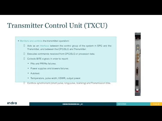
- 31. Transmitter Control Unit (TXCU) Monitors and controls the transmitter operation: Acts as an interface between the
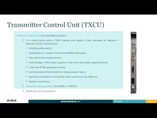
- 32. Transmitter Control Unit (TXCU) Monitors and controls the transmitter operation: If a critical failure occurs, TXCU
- 33. Transmitter Control Unit (TXCU)
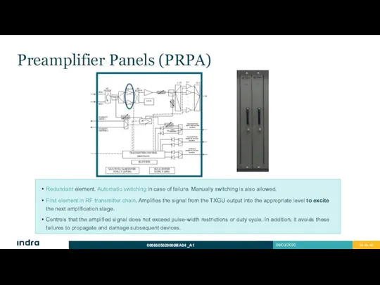
- 34. Preamplifier Panels (PRPA) Redundant element. Automatic switching in case of failure. Manually switching is also allowed.
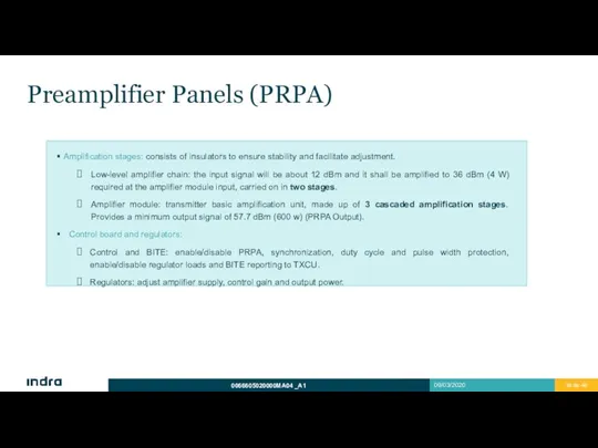
- 35. Preamplifier Panels (PRPA) Amplification stages: consists of insulators to ensure stability and facilitate adjustment. Low-level amplifier
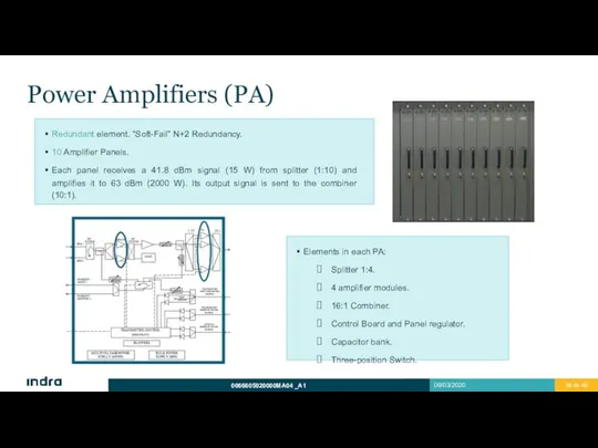
- 36. Power Amplifiers (PA) Redundant element. “Soft-Fail” N+2 Redundancy. 10 Amplifier Panels. Each panel receives a 41.8
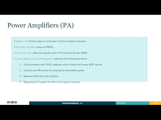
- 37. Power Amplifiers (PA) Splitter 1:4: Divides signal to distribute it into four amplifier modules. Amplifier modules:
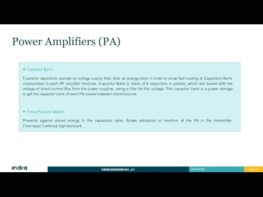
- 38. Power Amplifiers (PA) Capacitor Bank: 5 parallel capacitors operate as voltage supply filter. Acts as energy
- 39. Splitter/Combiner Assembly Back side of the transmitter rack. Stripline, low loss technology. Panels are connected directly
- 40. Blowers Assembly Redundant Unit. N+1 redundancy, it can operate with 2 out of 3 blowers. The
- 41. Power Supply Redundant units. N+1 redundancy. Two groups: MVPS y BPS. MVPS: Multi Voltage Power Supplies.
- 42. Auxiliary Elements Harmonic filter: harmonic level attenuation. Directional output coupler: provides samples of forward and reverse
- 43. Auxiliary Elements Takes samples to Radar Stability Monitor: Samples can be taken at 3 points, using
- 45. Скачать презентацию
Warning of Confidentiality
The data and information, in its totality or partial
Warning of Confidentiality
The data and information, in its totality or partial
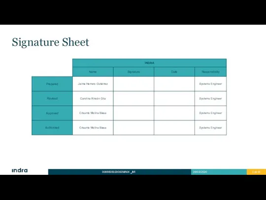
Signature Sheet
Signature Sheet
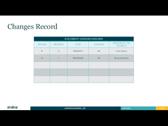
Changes Record
Changes Record
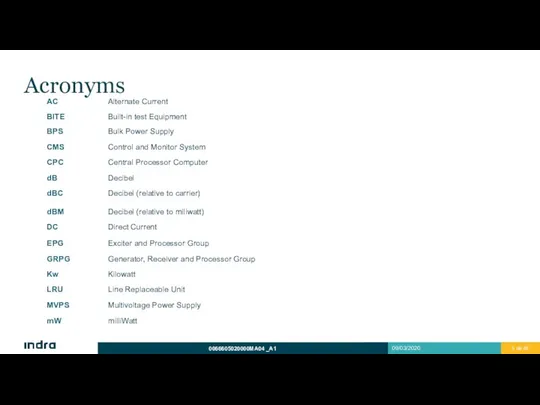
Acronyms
Acronyms
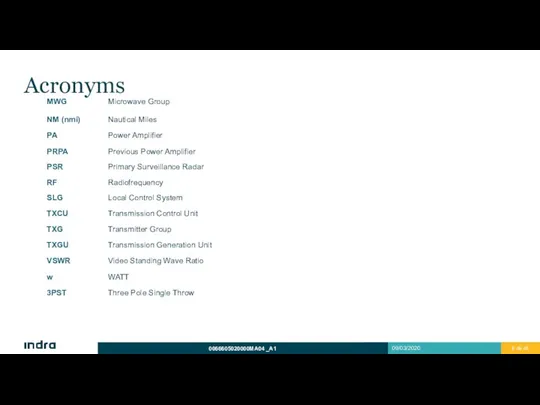
Acronyms
Acronyms
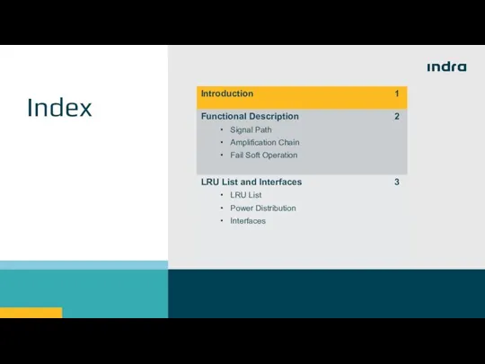
Index
Index
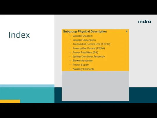
Index
Index
1
Introduction
1
Introduction
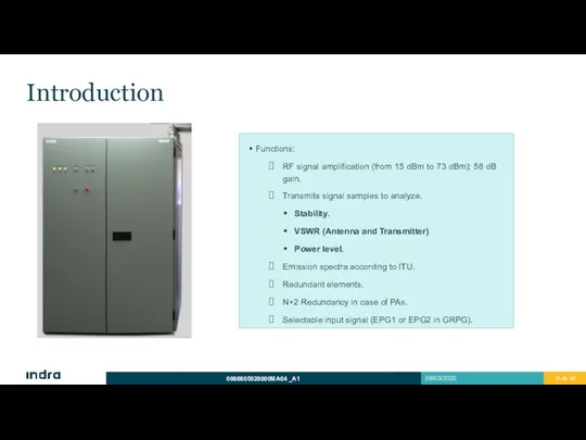
Introduction
Functions:
RF signal amplification (from 15 dBm to 73 dBm): 58 dB
Introduction
Functions:
RF signal amplification (from 15 dBm to 73 dBm): 58 dB
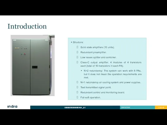
Introduction
Structure:
Solid state amplifiers (10 units).
Redundant preamplifier.
Low losses splitter and combiner.
Class-C output
Introduction
Structure:
Solid state amplifiers (10 units).
Redundant preamplifier.
Low losses splitter and combiner.
Class-C output
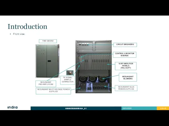
Introduction
Front view.
Introduction
Front view.
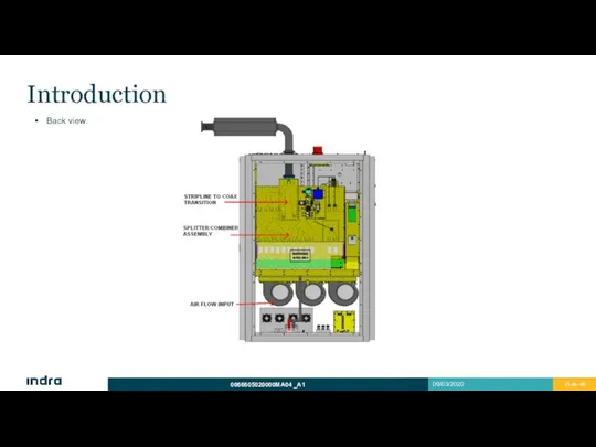
Introduction
Back view.
Introduction
Back view.
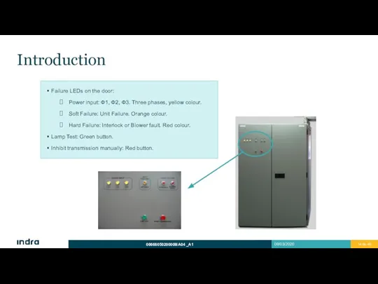
Introduction
Failure LEDs on the door:
Power input: Ф1, Ф2, Ф3. Three phases,
Introduction
Failure LEDs on the door:
Power input: Ф1, Ф2, Ф3. Three phases,

2
Signal Path
Amplification Chain
Soft Failure Operation
Functional Description
2
Signal Path
Amplification Chain
Soft Failure Operation
Functional Description
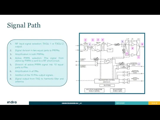
Signal Path
RF input signal selection: TXGU 1 or TXGU 2 output.
Signal
Signal Path
RF input signal selection: TXGU 1 or TXGU 2 output.
Signal
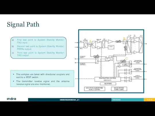
Signal Path
First test point to System Stability Monitor: TXG input.
Second test
Signal Path
First test point to System Stability Monitor: TXG input.
Second test
Signal Path
Signal Path
Amplification Chain
Soft Failure until 20% transistors had failed.
Peak Power 22 kW.
Dual
Amplification Chain
Soft Failure until 20% transistors had failed.
Peak Power 22 kW.
Dual
Fail-Soft Operation
Several transistors of the transmitter can fail without degrading radar
Fail-Soft Operation
Several transistors of the transmitter can fail without degrading radar
Fail-Soft Operation
This power reduction carries on a coverage reduction until 60
Fail-Soft Operation
This power reduction carries on a coverage reduction until 60
3
LRU List and Interfaces
LRU List
Power Distribution
Interfaces
3
LRU List and Interfaces
LRU List
Power Distribution
Interfaces
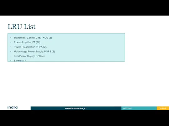
LRU List
Transmitter Control Unit, TXCU (2).
Power Amplifier, PA (10).
Power Preamplifier, PRPA
LRU List
Transmitter Control Unit, TXCU (2).
Power Amplifier, PA (10).
Power Preamplifier, PRPA
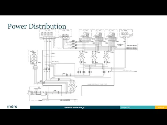
Power Distribution
Power Distribution
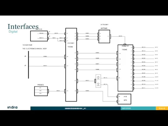
Interfaces
Digital
Interfaces
Digital
Interfaces
Coaxial
Interfaces
Coaxial
4
Subgroup Physical Description
General Diagram
General Description
Transmitter Control Unit (TXCU)
Preamplifier Panels (PRPA)
Power Amplifiers
4
Subgroup Physical Description
General Diagram
General Description
Transmitter Control Unit (TXCU)
Preamplifier Panels (PRPA)
Power Amplifiers
General Description
Transmitter subsystems:
RF amplification chain: amplifies the signal. It consists of
General Description
Transmitter subsystems:
RF amplification chain: amplifies the signal. It consists of
General Description
Transmitter subsystems:
Power supply assembly: consists of two groups, MVPSs and
General Description
Transmitter subsystems:
Power supply assembly: consists of two groups, MVPSs and
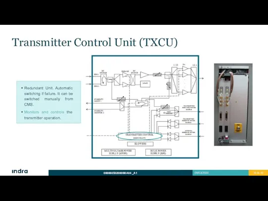
Transmitter Control Unit (TXCU)
Redundant Unit. Automatic switching if failure. It can
Transmitter Control Unit (TXCU)
Redundant Unit. Automatic switching if failure. It can
Transmitter Control Unit (TXCU)
Monitors and controls the transmitter operation:
Acts as an
Transmitter Control Unit (TXCU)
Monitors and controls the transmitter operation:
Acts as an
Transmitter Control Unit (TXCU)
Monitors and controls the transmitter operation:
If a critical
Transmitter Control Unit (TXCU)
Monitors and controls the transmitter operation:
If a critical
Transmitter Control Unit (TXCU)
Transmitter Control Unit (TXCU)
Preamplifier Panels (PRPA)
Redundant element. Automatic switching in case of failure. Manually
Preamplifier Panels (PRPA)
Redundant element. Automatic switching in case of failure. Manually
Preamplifier Panels (PRPA)
Amplification stages: consists of insulators to ensure stability and
Preamplifier Panels (PRPA)
Amplification stages: consists of insulators to ensure stability and
Power Amplifiers (PA)
Redundant element. “Soft-Fail” N+2 Redundancy.
10 Amplifier Panels.
Each panel receives
Power Amplifiers (PA)
Redundant element. “Soft-Fail” N+2 Redundancy.
10 Amplifier Panels.
Each panel receives
Power Amplifiers (PA)
Splitter 1:4: Divides signal to distribute it into four
Power Amplifiers (PA)
Splitter 1:4: Divides signal to distribute it into four
Power Amplifiers (PA)
Capacitor Bank:
5 parallel capacitors operate as voltage supply filter.
Power Amplifiers (PA)
Capacitor Bank:
5 parallel capacitors operate as voltage supply filter.
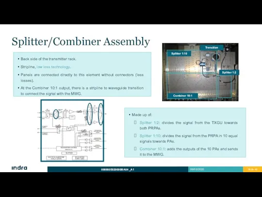
Splitter/Combiner Assembly
Back side of the transmitter rack.
Stripline, low loss technology.
Panels are
Splitter/Combiner Assembly
Back side of the transmitter rack.
Stripline, low loss technology.
Panels are
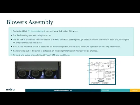
Blowers Assembly
Redundant Unit. N+1 redundancy, it can operate with 2 out
Blowers Assembly
Redundant Unit. N+1 redundancy, it can operate with 2 out
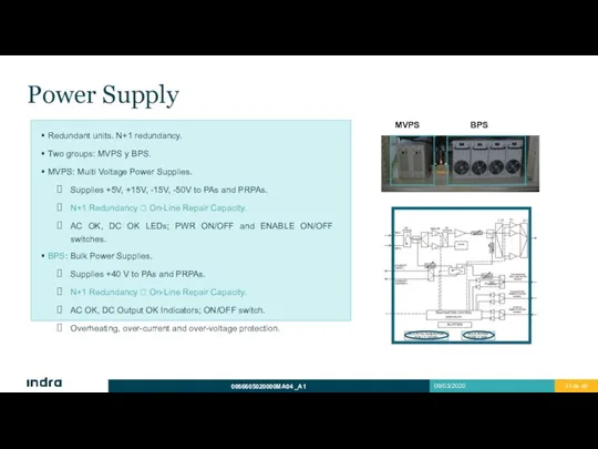
Power Supply
Redundant units. N+1 redundancy.
Two groups: MVPS y BPS.
MVPS: Multi Voltage
Power Supply
Redundant units. N+1 redundancy.
Two groups: MVPS y BPS.
MVPS: Multi Voltage

Auxiliary Elements
Harmonic filter: harmonic level attenuation.
Directional output coupler: provides samples
Auxiliary Elements
Harmonic filter: harmonic level attenuation.
Directional output coupler: provides samples
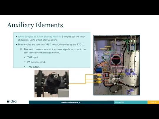
Auxiliary Elements
Takes samples to Radar Stability Monitor: Samples can be taken
Auxiliary Elements
Takes samples to Radar Stability Monitor: Samples can be taken
 Материалы для дистанционной поддержки учащихся по дополнительной программе
 Образовательный проект Кинезиология для детей и родителей
 Мораль
 Деревянные арки и рамы
 Традиции и новации в русской иконописи
 Время-деньги,
 Луценко В.Д. презентация 10 б
 Повышение клиентоориентированности многофункционального центра (МФЦ) Владимирской области
 Carsharing
 Фоторегистрационные и формные процессы
 Гаязов ГТИ
 Thermal processes of processing of petroleum raw materials
 Я. Моё имя, его происхождение
 MaakuntapäivänJulisteOppaat
 Природо-ресурсный потенциал Болгарии
 Производство и применение технических жидкостей и специальных продуктов масляного производства
 Путь к вершинам (возможности квадрокоптера)
 Творческий проект Умный дом
 Разработка бизнес-проекта утилизации отработанных автомобилей и его инженерное обеспечение
 Исследование и разработка способа пассивного компостирования птичьего помета в условиях Новгородской области
 Друзья познаются в беде
 Жизнь, посвященная медицине
 Контроллер Logik 9
 20140616_impressionizm
 На одной волне
 Сопротивление материалов
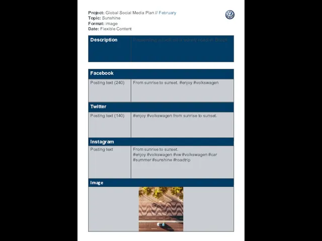 Global social media plan. Sunshine Format
 Влияние зарубежных агропромышленных ТНК на развитие российского зернового рынка