- Using Microcontrollers in Amateur Radio, an AZ EL Controller Application

Содержание
- 2. Things I Hope To Leave You With Share my experience with the rotor controller project Explain
- 3. Motivation For This Project Developed an interest in LEO (Low Earth Orbit) satellites Led to an
- 4. Low Earth Orbit Satellites Basically LEOs are orbital repeaters AMSAT has a lot of information on
- 5. LEO Satellites Vary In Both Size & Complexity AO-51 (Echo) ~800 km orbit voice repeater PakSat
- 6. Satellite QSOs Are Interesting! There are a lot of “things” involved in working the LEO satellites!
- 7. So Many things – So Little Time! The window for a QSO is often less than
- 8. My Approach To The Project Research the WEB for similar projects Evaluate what I might do
- 9. Why Use A Microcontroller Anyway?
- 10. Choices To Make Features Rotors Software Development tools & Environment Microcontroller
- 11. Desirable Features Work with the Nova tracking software Have 2 main modes: “manual” & “autotrack” Self-calibrate
- 12. The Rotor – You must understand the thing you are trying to control! The Alliance U100
- 13. Yes – You Can Stack Them Azimuth Elevation The ability to put a pipe through the
- 14. Anatomy Of A U100 Rotor #2
- 15. Anatomy Of A U100 Rotor #3 Physical stop tab Pulser Cam
- 16. Anatomy Of A U100 Rotor #4 Motor shaft Gear Pulsing contact Motor Frame Mechanical Stop
- 17. Commercial Controller for the U100 Rotor 10 degree graduations on the dial
- 18. The Original U100 Rotor Schematic Diagram Rotor Control Box Simply replace this with a Microcontroller System
- 19. Model of the U100 Rotor + - 360/ 0 Deg. 180 90 270 2. tics/deg =
- 20. Block Diagram Of the Rotor Controller Front Panel Switches Front Panel LEDs SS relays and Phasing
- 21. A FEW OF THE ATMEGA 16 FEATURES THE DATA SHEET IS 358 PAGES ! – 32
- 22. Microcontroller – Atmel Atmega16 YOU GET A LOT OF FUNCTIONALITY IN A SINGLE PACKAGE
- 23. Microcontroller – Save Time By Buying a Proto board I use this development board for almost
- 24. Partial Schematic of the Rotor Controller System – Rotor interfaces 30 VCT xfmr Solid State Relays
- 25. Front Panel Switches – Interface to the Microcontroller Micro Controller Port assignments (Active low) Port A
- 26. Development Environment Rotor control cable Debug data Serial port Program flash memory using “avrdude” utility Fedora
- 27. Features On My Rotor Control Box 2X16 BACKLIGHTED LCD SPST N.O. Pushbutton N.O. Pushbutton ON-OFF-ON ON-OFF-ON
- 28. Manual Mode - AZ & EL Reading
- 29. Auto track mode – tracking AO-10 satellite
- 30. The Rotor Teststand
- 31. A Look Under The Hood Rotor power Controller Board Xfmr for controller board Phasing caps/SS relay
- 32. A Few Software Statistics ATMEGA 16 Controller 16KBytes Flash (Program) memory 512 Bytes of EEPROM 1
- 33. High Level Software Design BACKGROUND processing every 5 milliseconds Watch every switch in the system Monitor
- 34. Field Day 2008 Satellite Antenna Setup
- 35. Performance Of The Controller Used successfully in last two Field Days Sensitive to drag on the
- 36. Things Left Undone Need to get a better schematic in electronic form Scattered around in a
- 37. Closing Thoughts About Antenna Rotors Pulsers have many issues to consider Resolution - must interpolate Calibration
- 39. Скачать презентацию

Things I Hope To Leave You With
Share my experience with the
Things I Hope To Leave You With
Share my experience with the
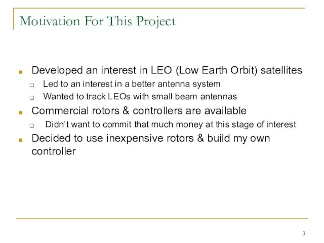
Motivation For This Project
Developed an interest in LEO (Low Earth Orbit)
Motivation For This Project
Developed an interest in LEO (Low Earth Orbit)
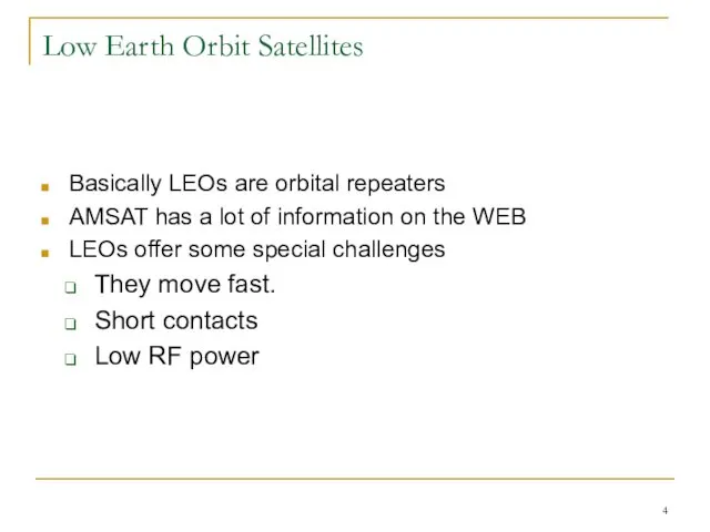
Low Earth Orbit Satellites
Basically LEOs are orbital repeaters
AMSAT has a lot
Low Earth Orbit Satellites
Basically LEOs are orbital repeaters
AMSAT has a lot

LEO Satellites Vary In Both Size & Complexity
AO-51 (Echo)
~800 km
LEO Satellites Vary In Both Size & Complexity
AO-51 (Echo)
~800 km
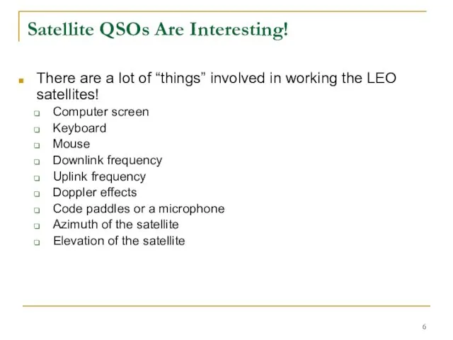
Satellite QSOs Are Interesting!
There are a lot of “things” involved in
Satellite QSOs Are Interesting!
There are a lot of “things” involved in

So Many things – So Little Time!
The window for a QSO
So Many things – So Little Time!
The window for a QSO
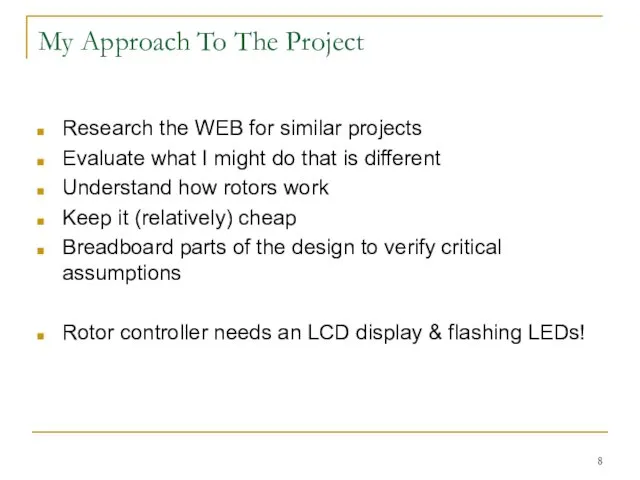
My Approach To The Project
Research the WEB for similar projects
Evaluate what
My Approach To The Project
Research the WEB for similar projects
Evaluate what

Why Use A Microcontroller Anyway?
Why Use A Microcontroller Anyway?
Choices To Make
Features
Rotors
Software Development tools & Environment
Microcontroller
Choices To Make
Features
Rotors
Software Development tools & Environment
Microcontroller

Desirable Features
Work with the Nova tracking software
Have 2 main modes: “manual”
Desirable Features
Work with the Nova tracking software
Have 2 main modes: “manual”

The Rotor – You must understand the thing you are trying
The Rotor – You must understand the thing you are trying

Yes – You Can Stack Them
Azimuth
Elevation
The ability to put a pipe
Yes – You Can Stack Them
Azimuth
Elevation
The ability to put a pipe

Anatomy Of A U100 Rotor #2
Anatomy Of A U100 Rotor #2

Anatomy Of A U100 Rotor #3
Physical stop tab
Pulser Cam
Anatomy Of A U100 Rotor #3
Physical stop tab
Pulser Cam

Anatomy Of A U100 Rotor #4
Motor shaft Gear
Pulsing contact
Motor Frame
Mechanical Stop
Anatomy Of A U100 Rotor #4
Motor shaft Gear
Pulsing contact
Motor Frame
Mechanical Stop

Commercial Controller for the U100 Rotor
10 degree graduations on the dial
Commercial Controller for the U100 Rotor
10 degree graduations on the dial

The Original U100 Rotor Schematic Diagram
Rotor
Control Box
Simply replace this with a
The Original U100 Rotor Schematic Diagram
Rotor
Control Box
Simply replace this with a

Model of the U100 Rotor
+
-
360/ 0 Deg.
180
90
270
2. tics/deg = tics/pulse /
Model of the U100 Rotor
+
-
360/ 0 Deg.
180
90
270
2. tics/deg = tics/pulse /

Block Diagram Of the Rotor Controller
Front Panel Switches
Front Panel LEDs
SS relays
Block Diagram Of the Rotor Controller
Front Panel Switches
Front Panel LEDs
SS relays

A FEW OF THE ATMEGA 16 FEATURES
THE DATA SHEET IS 358
A FEW OF THE ATMEGA 16 FEATURES
THE DATA SHEET IS 358

Microcontroller – Atmel Atmega16
YOU GET A LOT OF FUNCTIONALITY IN A
Microcontroller – Atmel Atmega16
YOU GET A LOT OF FUNCTIONALITY IN A
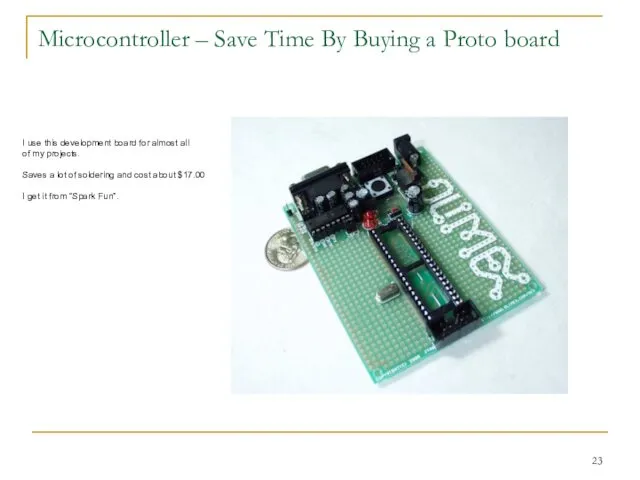
Microcontroller – Save Time By Buying a Proto board
I use this
Microcontroller – Save Time By Buying a Proto board
I use this

Partial Schematic of the Rotor Controller System – Rotor interfaces
30 VCT
Partial Schematic of the Rotor Controller System – Rotor interfaces
30 VCT

Front Panel Switches – Interface to the Microcontroller
Micro Controller Port assignments
Front Panel Switches – Interface to the Microcontroller
Micro Controller Port assignments

Development Environment
Rotor control cable
Debug data Serial port
Program flash memory
using “avrdude”
Development Environment
Rotor control cable
Debug data Serial port
Program flash memory
using “avrdude”

Features On My Rotor Control Box
2X16 BACKLIGHTED LCD
SPST
N.O. Pushbutton
N.O. Pushbutton
ON-OFF-ON
ON-OFF-ON
Indicates rotor
Features On My Rotor Control Box
2X16 BACKLIGHTED LCD
SPST
N.O. Pushbutton
N.O. Pushbutton
ON-OFF-ON
ON-OFF-ON
Indicates rotor

Manual Mode - AZ & EL Reading
Manual Mode - AZ & EL Reading

Auto track mode – tracking AO-10 satellite
Auto track mode – tracking AO-10 satellite

The Rotor Teststand
The Rotor Teststand

A Look Under The Hood
Rotor power
Controller Board
Xfmr for controller board
Phasing caps/SS
A Look Under The Hood
Rotor power
Controller Board
Xfmr for controller board
Phasing caps/SS

A Few Software Statistics
ATMEGA 16 Controller
16KBytes Flash (Program) memory
512 Bytes of
A Few Software Statistics
ATMEGA 16 Controller
16KBytes Flash (Program) memory
512 Bytes of

High Level Software Design
BACKGROUND processing every 5 milliseconds
Watch every switch in
High Level Software Design
BACKGROUND processing every 5 milliseconds
Watch every switch in

Field Day 2008 Satellite Antenna Setup
Field Day 2008 Satellite Antenna Setup

Performance Of The Controller
Used successfully in last two Field Days
Sensitive
Performance Of The Controller
Used successfully in last two Field Days
Sensitive

Things Left Undone
Need to get a better schematic in electronic form
Scattered
Things Left Undone
Need to get a better schematic in electronic form
Scattered

Closing Thoughts About Antenna Rotors
Pulsers have many issues to consider
Resolution -
Closing Thoughts About Antenna Rotors
Pulsers have many issues to consider
Resolution -
 20160204_ur_2_._s_dobrym_utrom
 Геофизические исследования скважин
 Некоторые свойства прямоугольных треугольников. Решение задач
 Приспособленность
 Шахталық сутөкпе қондырғылары
 Женская цитология
 Патриарх Авраам
 Мастерская Деда Мороза
 Басня
Басня Автомобільна сигналізація Magnum Smart S20
 20180424_literaturnye_geroi
 Выражение характера животных
 Комфортная городская среда: г. Петрозаводск, Лососинское шоссе, д. 28
 Тренды 2020 в интерьере
 Контактная точечная сварка
 Открытки для мамы
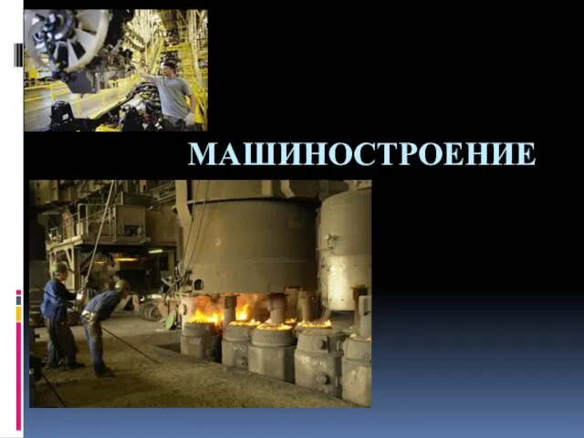 Отрасли машиностроения
 Презентация1
 С любовью к телу: как популярность бодипозитива влияет на общество и экономику?
 Повесть СОвременных лет
 20120114_stihotvorenie_lermontova
 Красота вокруг нас
 Как научить рисовать животных
 Презентация (1)
 20110618_Illyustracii_k_romanu_Evgeniy_onegin
 Электромеханический переключатель
 Установка панелей наружных и внутренних стен зданий
 Проектирование средств океанотехники