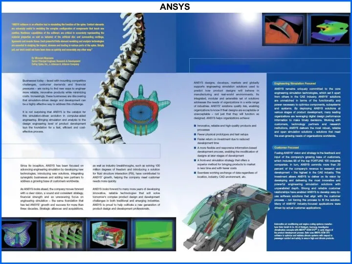
- ANSYS

Содержание
- 2. Agenda Finite element method ANSYS Inc ANSYS Multiphysics
- 3. Basic steps in Finite element method 1. Create and discretize the solution domain into finite elements.
- 5. ANSYS
- 6. Detail Geometry Creation Solid geometry of an assembly Geometry representing the air around an electric motor
- 7. ANSYS Multiphysics (examples)
- 8. ANSYS Multiphysics (examples)
- 9. ANSYS CFX
- 11. Скачать презентацию
Agenda
Finite element method
ANSYS Inc
ANSYS Multiphysics
Agenda
Finite element method
ANSYS Inc
ANSYS Multiphysics
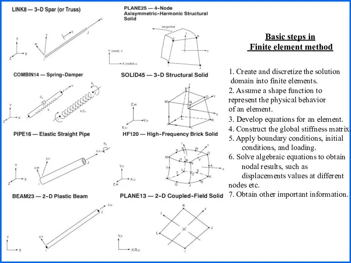
Basic steps in
Finite element method
1. Create and discretize the
Basic steps in
Finite element method
1. Create and discretize the
ANSYS
ANSYS
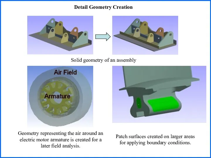
Detail Geometry Creation
Solid geometry of an assembly
Geometry representing the air
Detail Geometry Creation
Solid geometry of an assembly
Geometry representing the air
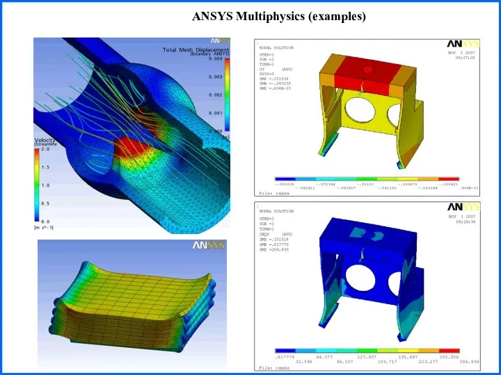
ANSYS Multiphysics (examples)
ANSYS Multiphysics (examples)
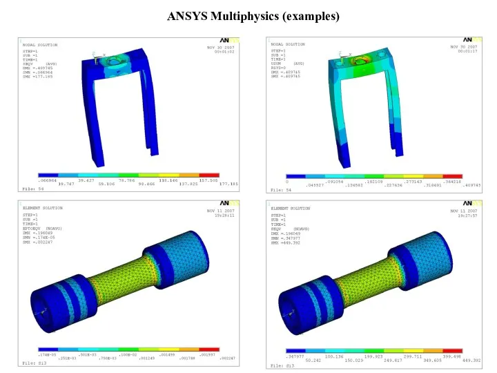
ANSYS Multiphysics (examples)
ANSYS Multiphysics (examples)
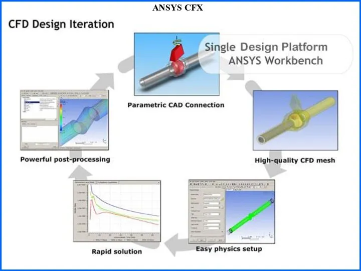
ANSYS CFX
ANSYS CFX
 «Зимний запас» по Н. Сладкову Учитель: Оксана Геннадьевна Савина
 Мониторинг в образовании
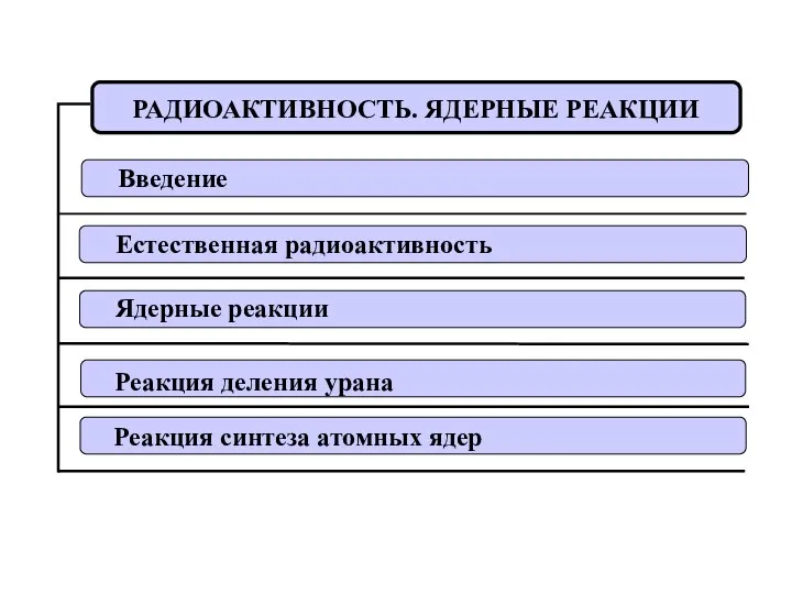 Радиоактивность. ядерные реакции
  Биокоррозия
  ПЕЙЗАЖ Автор: Гусев М. М.
  АЛГЕБРА 7 КЛАСС Решение систем линейных уравнений
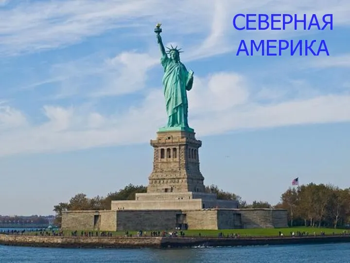 Северная Америка
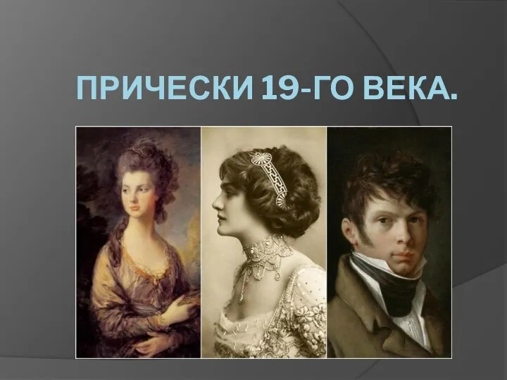 Прически XIX века
 Актуальные направления деятельности ГДОУ на 2011-2012 гг. Овечкина Т.А. – к.п.н., заведующий Института детства СПб АППО
 Урок – путешествие в город Здоровейск. Учитель СБО РГОУ «Цивильская специальная (коррекционная) школа – интернат №2» Михайлова И
 Демократичний політичний режим
 Синтез дискретных систем методом желаемых частотных характеристик
 Проценты в гостях в Простоквашино - презентация по Алгебре
 Архив чертежей ТМЦ. Шаблон
 Functions are objects. Main concepts behind Python functions
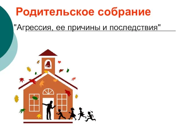 Презентация на тему "Родительское собрание про агрессию" - скачать презентации по Педагогике
 Travelplat project status
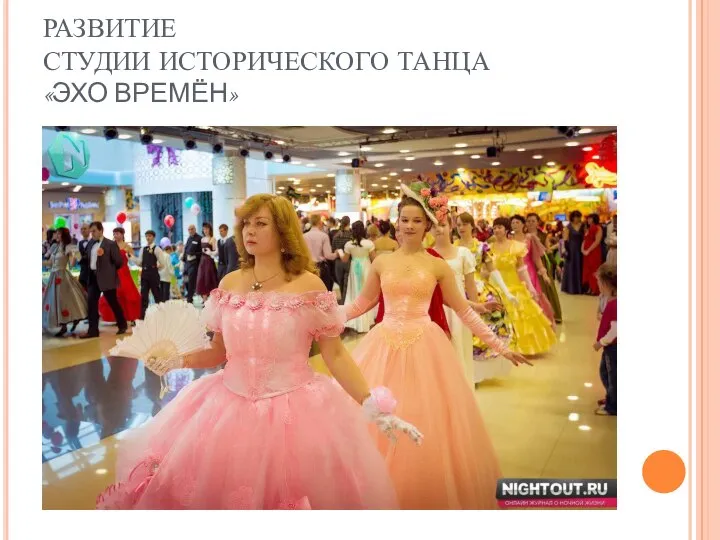 Развитие студии исторического танца «Эхо времён»
 Основные правила построения статистических таблиц.
 Zależności funkcyjne. Aksjomaty Armstronga
 Операційні системи. Реалізація файлових систем
 Информационно–аналитический центр комплекса градостроительной политики и строительства города Москвы «Мосстройинформ»
 Тема
Тема Формат сериализованного объекта в Java. (Лекция 10)
 Региональный налог на производственную деятельность Италии
 Л.П. Булатова
 Технология устройства теплоизоляции ограждающих конструкций зданий с применением вакуумных теплоизоляционных панелей
 Презентация "экономика семьи" - скачать презентации по Экономике