- Repair Manual. Citaq Android POS

Содержание
- 2. CITAQ V8 Parameter
- 3. CITAQ V8 Parameter
- 4. 1.CITAQ V8 Disassembly
- 5. 1.1 Appearance---Front 3 1:8’’ touch screen(Capacity) 2:Indicator 3: V8 cover 4:Side USB port 4 Press the
- 6. 1.1Appearance---Back 1:Power Switch 2:Lan Port 3:Rear USBX2, RS232 x 1 4:Adaptor port 5:Cash drawer port 1
- 7. 1.1 Internal view 1:Printer mechanism 2:Mechanism 3、4:Paper feeder rolls X4 5:SIM、TF card slot 1 2 3
- 8. 1.2 Host unit disassembly 1.2.1 Disassembly of Plastic Base 1、Take out screws marked 2、Turn the switch
- 9. 1.2 Host unit disassembly 1.2.2 Disassemble the screen 1、Unscrew all screws marked in pic 2、Lift the
- 10. 1.2 Host Unit Disassembly 1.2.3 Disassemble the Screen cables 1、Pry the breaches pic showed by a
- 11. 1.2 Host Unit Disassembly 1.2.4 Disassemble the base metal cover 1、Unscrew the marked screws and push
- 12. 1.2 Host Unit Disassembly 1.2.5 Disassemble the printer board Switch Cable Sensor Printer Head USB Connect
- 13. 1.2 Host Unit Disassembly 1.2.6 Disassemble the plastic frame 1、Unscrew the marked screws and open the
- 14. 1.2 Host Unit Disassembly 1.2.2 Disassemble the sensor 1、Unscrew the marked screws to take sensor apart.
- 15. 1.2 Host Unit Disassembly 1.2.6 Disassemble the printer mechanism 1、Cut the marked plastic wire 2、Unscrew the
- 16. 1.2 Host Unit Disassembly 1.2.7 Disassemble the printer mechanism 1、Take out the connector from cable slot,
- 17. 1.3 Host Unit Disassembly 1.3.1 Disassemble screen back 1、Unscrew the marked screws to take out this
- 18. 1.3 Host Unit Disassembly 1.3.2 Disassemble Main board 1、Pull out WIFI cable 2、Push out the marked
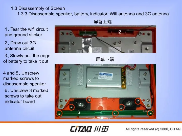
- 19. 1.3 Disassembly of Screen 1.3.3 Disassemble speaker, battery, indicator, Wifi antenna and 3G antenna 1、Tear the
- 20. 1.3 Disassembly of Screen 1.3.4 Disassemble metal fixture of screen 1、Remove marked screws to disassemble the
- 21. 1.3 Disassembly of Screen 1.3.5 Disassemble LCD Panel 1、First to pull up the edge of LCD
- 22. 1.3 Disassembly of Screen 1.3.6 Disassemble touch screen 1、Firstly heat up the edges which marked in
- 23. 2.CITAQ V8 FAQ
- 24. V8 FAQ and solution 1、Eliminate the black screen when turning on Try to replace LCD panel
- 26. Скачать презентацию
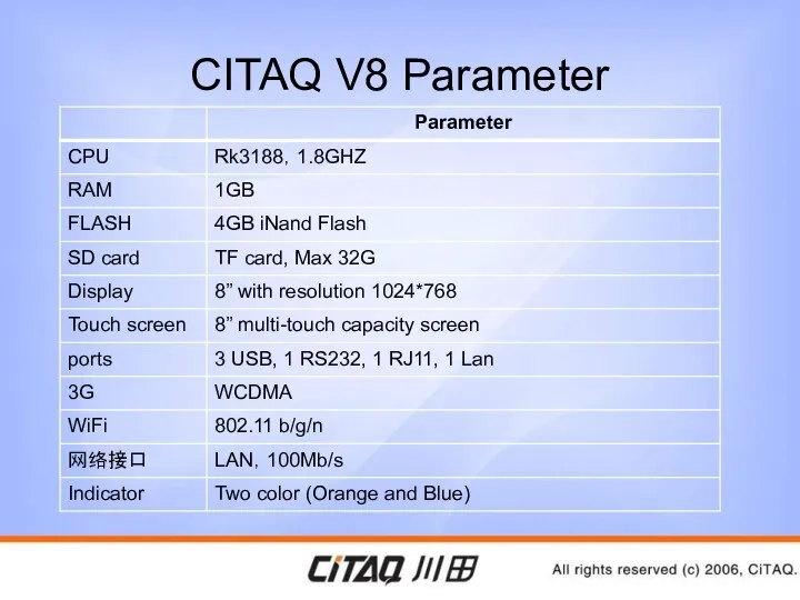
CITAQ V8 Parameter
CITAQ V8 Parameter

CITAQ V8 Parameter
CITAQ V8 Parameter
1.CITAQ V8 Disassembly
1.CITAQ V8 Disassembly
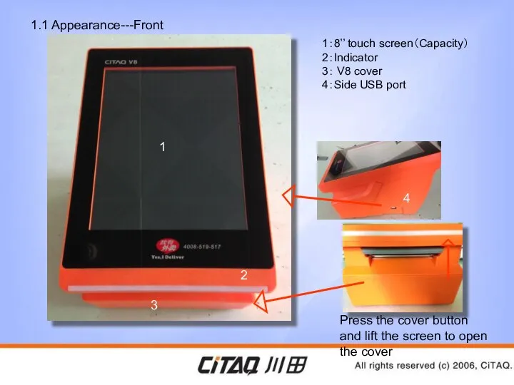
1.1 Appearance---Front
3
1:8’’ touch screen(Capacity)
2:Indicator
3: V8 cover
4:Side USB port
4
Press the cover button
1.1 Appearance---Front
3
1:8’’ touch screen(Capacity)
2:Indicator
3: V8 cover
4:Side USB port
4
Press the cover button
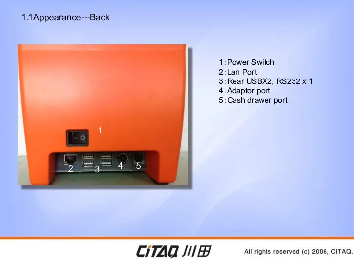
1.1Appearance---Back
1:Power Switch
2:Lan Port
3:Rear USBX2, RS232 x 1
4:Adaptor port
5:Cash drawer port
1
2
3
4
5
1.1Appearance---Back
1:Power Switch
2:Lan Port
3:Rear USBX2, RS232 x 1
4:Adaptor port
5:Cash drawer port
1
2
3
4
5

1.1 Internal view
1:Printer mechanism
2:Mechanism
3、4:Paper feeder rolls X4
5:SIM、TF card slot
1
2
3
4
5
1.1 Internal view
1:Printer mechanism
2:Mechanism
3、4:Paper feeder rolls X4
5:SIM、TF card slot
1
2
3
4
5
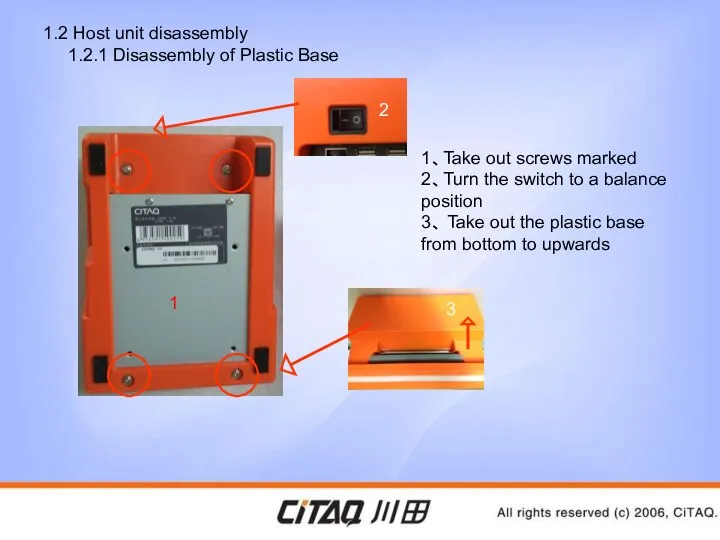
1.2 Host unit disassembly
1.2.1 Disassembly of Plastic Base
1、Take out screws
1.2 Host unit disassembly
1.2.1 Disassembly of Plastic Base
1、Take out screws
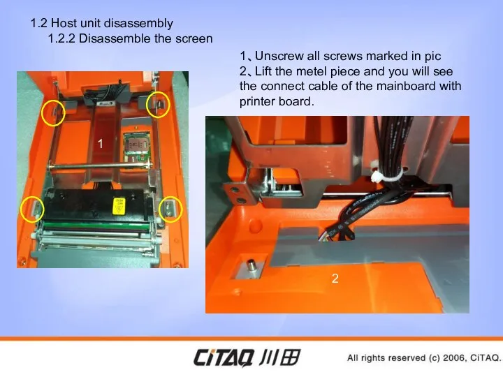
1.2 Host unit disassembly 1.2.2 Disassemble the screen
1、Unscrew all screws marked
1.2 Host unit disassembly 1.2.2 Disassemble the screen
1、Unscrew all screws marked

1.2 Host Unit Disassembly
1.2.3 Disassemble the Screen cables
1、Pry the breaches
1.2 Host Unit Disassembly
1.2.3 Disassemble the Screen cables
1、Pry the breaches
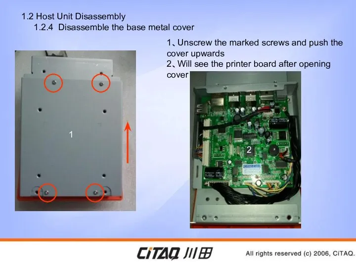
1.2 Host Unit Disassembly
1.2.4 Disassemble the base metal cover
1、Unscrew the
1.2 Host Unit Disassembly
1.2.4 Disassemble the base metal cover
1、Unscrew the
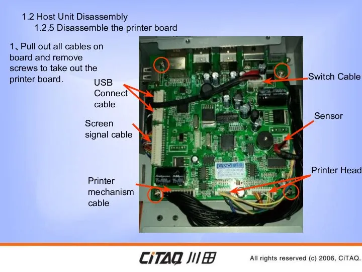
1.2 Host Unit Disassembly 1.2.5 Disassemble the printer board
Switch Cable
Sensor
Printer
1.2 Host Unit Disassembly 1.2.5 Disassemble the printer board
Switch Cable
Sensor
Printer
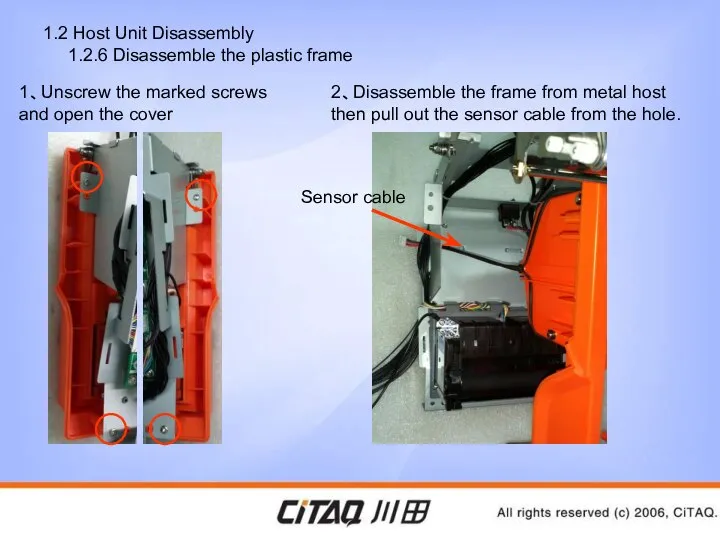
1.2 Host Unit Disassembly 1.2.6 Disassemble the plastic frame
1、Unscrew the marked
1.2 Host Unit Disassembly 1.2.6 Disassemble the plastic frame
1、Unscrew the marked

1.2 Host Unit Disassembly 1.2.2 Disassemble the sensor
1、Unscrew the marked screws
1.2 Host Unit Disassembly 1.2.2 Disassemble the sensor
1、Unscrew the marked screws
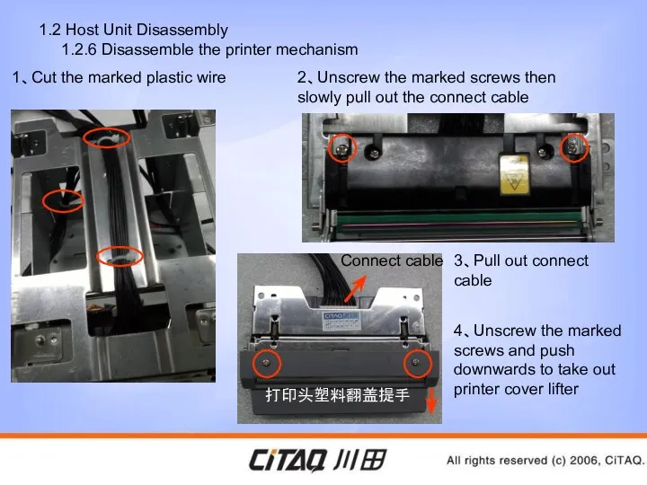
1.2 Host Unit Disassembly 1.2.6 Disassemble the printer mechanism
1、Cut the marked
1.2 Host Unit Disassembly 1.2.6 Disassemble the printer mechanism
1、Cut the marked

1.2 Host Unit Disassembly 1.2.7 Disassemble the printer mechanism
1、Take out the
1.2 Host Unit Disassembly 1.2.7 Disassemble the printer mechanism
1、Take out the
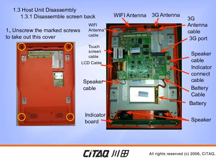
1.3 Host Unit Disassembly 1.3.1 Disassemble screen back
1、Unscrew the marked screws
1.3 Host Unit Disassembly 1.3.1 Disassemble screen back
1、Unscrew the marked screws
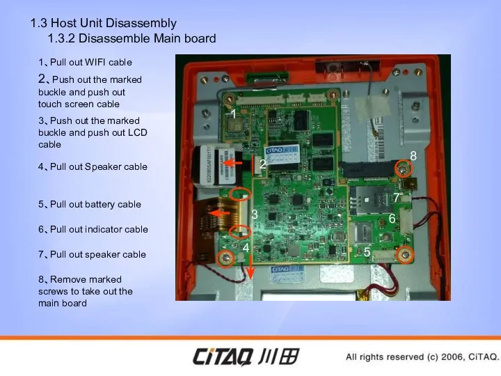
1.3 Host Unit Disassembly 1.3.2 Disassemble Main board
1、Pull out WIFI cable
2、Push
1.3 Host Unit Disassembly 1.3.2 Disassemble Main board
1、Pull out WIFI cable
2、Push
1.3 Disassembly of Screen
1.3.3 Disassemble speaker, battery, indicator, Wifi antenna
1.3 Disassembly of Screen 1.3.3 Disassemble speaker, battery, indicator, Wifi antenna
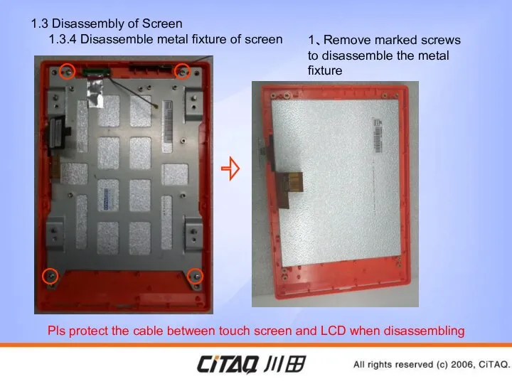
1.3 Disassembly of Screen 1.3.4 Disassemble metal fixture of screen
1、Remove marked
1.3 Disassembly of Screen 1.3.4 Disassemble metal fixture of screen
1、Remove marked

1.3 Disassembly of Screen 1.3.5 Disassemble LCD Panel
1、First to pull up
1.3 Disassembly of Screen 1.3.5 Disassemble LCD Panel
1、First to pull up

1.3 Disassembly of Screen 1.3.6 Disassemble touch screen
1、Firstly heat up the
1.3 Disassembly of Screen 1.3.6 Disassemble touch screen
1、Firstly heat up the

2.CITAQ V8 FAQ
2.CITAQ V8 FAQ

V8 FAQ and solution
1、Eliminate the black screen when turning on
Try to
V8 FAQ and solution
1、Eliminate the black screen when turning on
Try to
 ГОСТ 7.0-99 «Информационно-библиотечная деятельность, библиография. Термины и определения»
 Дзюдо в детском саду. Учебная программа составлена с учётом возраста обучающихся (мальчики и девочки) – 5-7 лет
 Основы строительной стандартизации
 Комбинаторные задачи и начальные сведения из теории вероятностей в курсе алгебры 9 класса.
  Сборка компьютера. (Глава 3)
 Модули
 Кредитование внешнеторговых операций Выполнили: Жукова Юлия Жукова Зоя
 Організація оповіщення про хімічні надзвичайні ситуації
 Общая характеристика системы физического воспитания
 Языкознание эпохи Возрождения
 Ecowiki.ru Вики-портал – площадка для сбора единой базы актуальных знаний и ресурсов по различным эко-направлениям Рассылка: ecowiki@googlegrou
 Чрезвычайные ситуации
 kishechnye_shvy
 Средства наблюдения
 эко
эко Компонувальник. Патерни проектування
 Коффердам
 Предпосылки модернизации системы подготовки спортивного резерва в Российской Федерации и ход ее реализации
 Значение массажа в системе устранения заикания
 История развития и современное состояние оздоровительной и адаптивной физической культуры
 Обзор изменений и нововведений в законодательстве для субъектов малого предпринимательства в 2018-2019 годах
 Комбинационные цифровые схемы
 Презентация на тему "Инактивированные вакцины" - скачать презентации по Медицине
 Сканирующий тахеометр Trimble SX10
 Размещение в документе графики
 Соціальні норми в Об’єднаних Арабських Еміратах
 Техническая защита информации
 В каждой мимолётности вижу я миры.