- Battery. Direct and Alternating current

Содержание
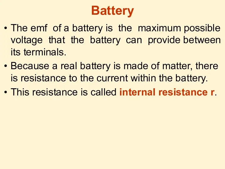
- 2. Battery The emf of a battery is the maximum possible voltage that the battery can provide
- 3. Direct and Alternating current There exist two types of current: Direct current (dc) is the continuous
- 4. Vb-Va: V= - IR Circuit current: I= /(R+r) Power output of the battery is *I:
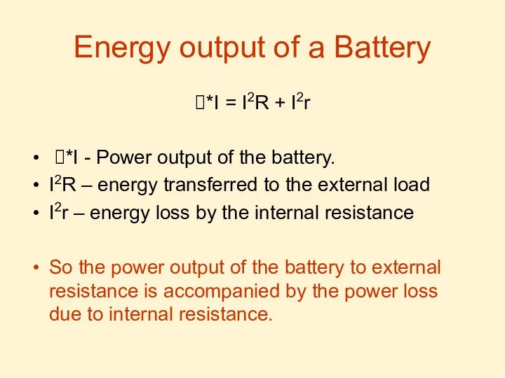
- 5. Energy output of a Battery *I = I2R + I2r *I - Power output of the
- 6. Resistor Resistor is a circuit element which is used to control the current level in the
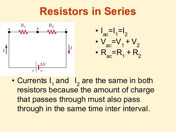
- 7. Resistors in Series Iac=I1=I2 Vac=V1 + V2 Rac=R1 + R2 Currents I1 and I2 are the
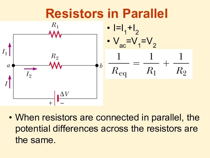
- 8. Resistors in Parallel I=I1+I2 Vac=V1=V2 When resistors are connected in parallel, the potential differences across the
- 9. Any number of resistors In series: I=I1=I2=I3=… V=V1 + V2 + V3 + … Rac=R1 +
- 10. Kirchhoff’s Rules for Direct Current Circuits Junction rule. The sum of the currents entering any junction
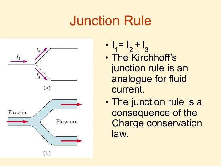
- 11. Junction Rule I1= I2 + I3 The Kirchhoff’s junction rule is an analogue for fluid current.
- 12. Loop Rule Basis Kirchhoff’s second rule follows from the law of conservation of energy. Let us
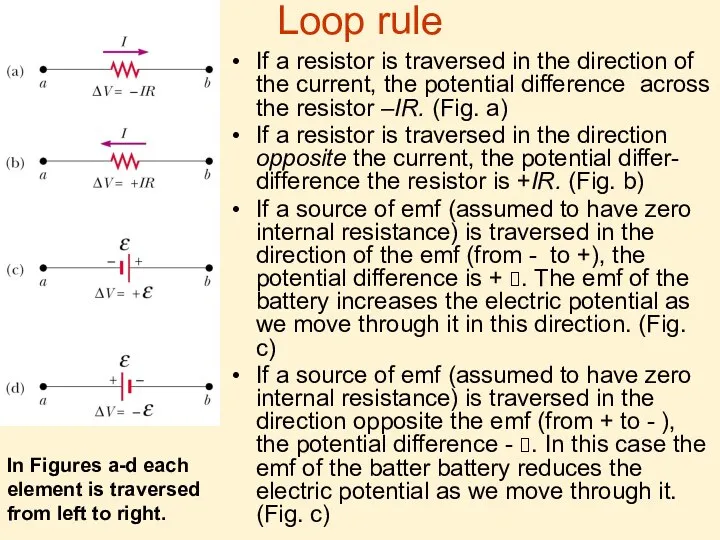
- 13. Loop rule If a resistor is traversed in the direction of the current, the potential difference
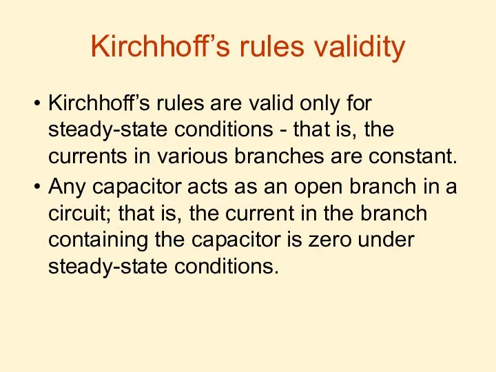
- 14. Kirchhoff’s rules validity Kirchhoff’s rules are valid only for steady-state conditions - that is, the currents
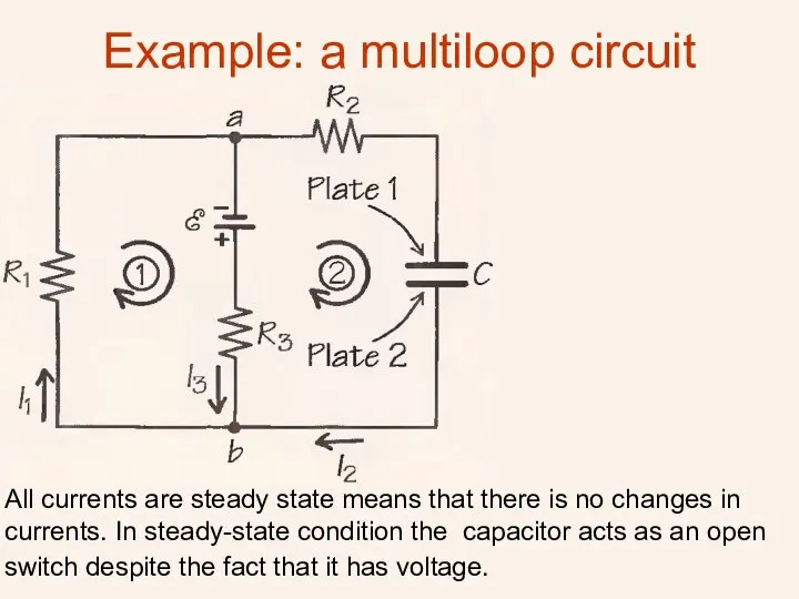
- 16. Example: a multiloop circuit All currents are steady state means that there is no changes in
- 17. So first we choose directions in the two circuits as it shown in the picture. I2=0,
- 19. Скачать презентацию
Battery
The emf of a battery is the maximum possible voltage that
Battery
The emf of a battery is the maximum possible voltage that
Direct and Alternating current
There exist two types of current:
Direct current
Direct and Alternating current
There exist two types of current:
Direct current
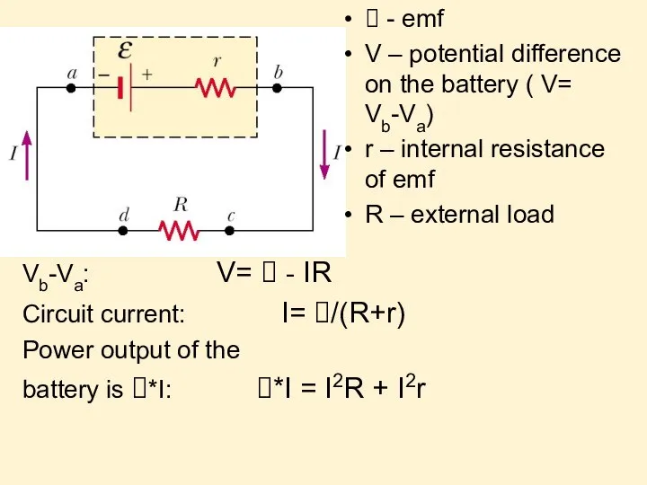
Vb-Va: V= - IR
Circuit current: I= /(R+r)
Power output of the
battery is
Vb-Va: V= - IR
Circuit current: I= /(R+r)
Power output of the
battery is
Energy output of a Battery
*I = I2R + I2r
*I -
Energy output of a Battery
*I = I2R + I2r
*I -
Resistor
Resistor is a circuit element which is used to control the
Resistor
Resistor is a circuit element which is used to control the
Resistors in Series
Iac=I1=I2
Vac=V1 + V2
Rac=R1 + R2
Currents I1 and I2 are
Resistors in Series
Iac=I1=I2
Vac=V1 + V2
Rac=R1 + R2
Currents I1 and I2 are
Resistors in Parallel
I=I1+I2
Vac=V1=V2
When resistors are connected in parallel, the potential differences
Resistors in Parallel
I=I1+I2
Vac=V1=V2
When resistors are connected in parallel, the potential differences
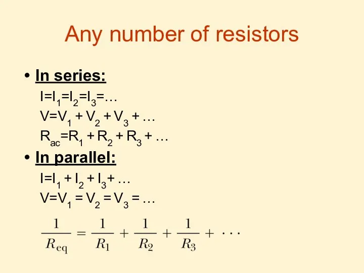
Any number of resistors
In series:
I=I1=I2=I3=…
V=V1 + V2 + V3 + …
Rac=R1
Any number of resistors
In series:
I=I1=I2=I3=…
V=V1 + V2 + V3 + …
Rac=R1
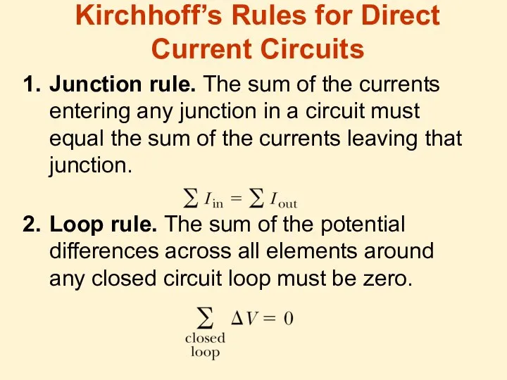
Kirchhoff’s Rules for Direct Current Circuits
Junction rule. The sum of the
Kirchhoff’s Rules for Direct Current Circuits
Junction rule. The sum of the
Junction Rule
I1= I2 + I3
The Kirchhoff’s junction rule is an analogue
Junction Rule
I1= I2 + I3
The Kirchhoff’s junction rule is an analogue
Loop Rule Basis
Kirchhoff’s second rule follows from the law of conservation
Loop Rule Basis
Kirchhoff’s second rule follows from the law of conservation
Loop rule
If a resistor is traversed in the direction of the
Loop rule
If a resistor is traversed in the direction of the
Kirchhoff’s rules validity
Kirchhoff’s rules are valid only for steady-state conditions -
Kirchhoff’s rules validity
Kirchhoff’s rules are valid only for steady-state conditions -
Example: a multiloop circuit
All currents are steady state means that there
Example: a multiloop circuit
All currents are steady state means that there
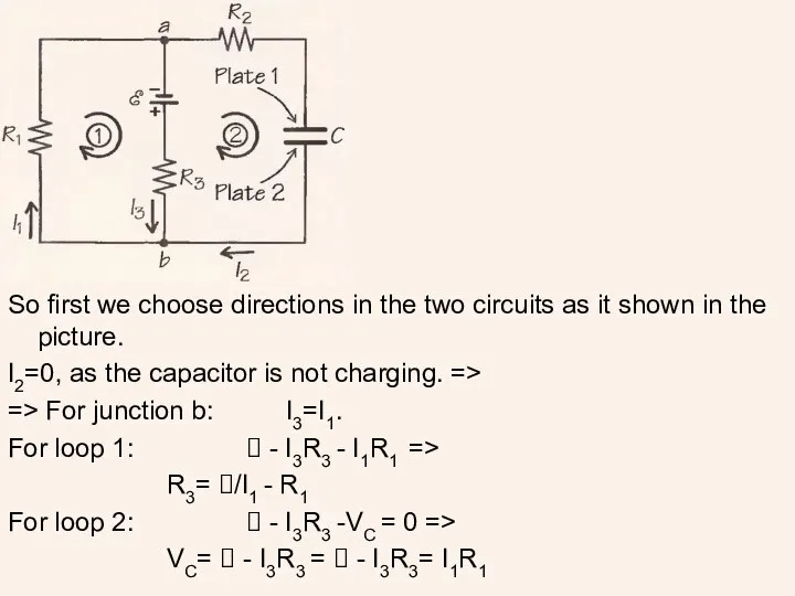
So first we choose directions in the two circuits as it
So first we choose directions in the two circuits as it
 Магнитное поле. Сила Ампера. Магнитная индукция
 Технология монтажа и технического обслуживания измерительных приборов
 Основные положения молекулярно-кинетической теории
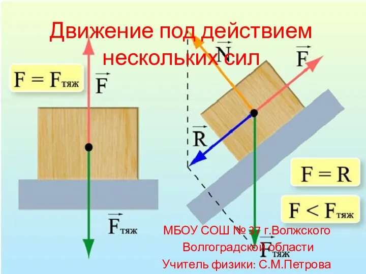 Движение под действием нескольких сил МБОУ СОШ № 37 г.Волжского Волгоградской области Учитель физики: С.М.Петрова
 Валы и оси
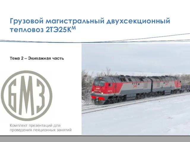 2. Экипажная часть
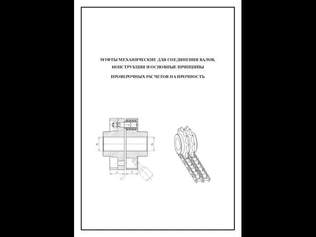 Муфты механические для соединения валов, конструкция и основные принципы проверочных расчетов на прочность
 Перемещение. Путь
 Центр тяжести
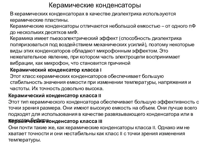 Керамические конденсаторы
 Абрам Федорович Иоффе — учитель нескольких поколений отечественных физиков
 Рентгеновское излучение
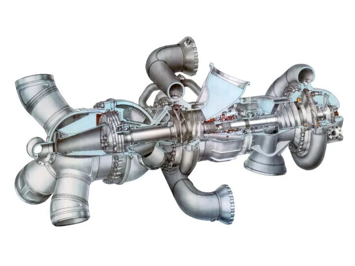 Конструкция турбонасосного агрегата
 Стульчик для огорода
 Явление электромагнитной индукции
 Дифференциальное уравнение энергии трехмерной нестационарной теплопроводности твердых тел
 Преломление световых лучей
 Термодинамическая картина мира
 Испытания, эксплуатация, техническое обслуживание металлорежущего оборудования
 Закон Кулона. Единица электрического заряда
 Тепловозные дизели
 Лабораторная работа. Кривошипно-шатунный механизм
 ФИЗИКА – 8 урок №51
 Понятие формирующего фильтра и его свойства
 "Зависимость скорости испарения воды от площади поверхности и от ветра" Выполнил ученик
  Презентация по физике "магнитное поле1" - скачать бесплатно
 Досліди Д. Франка і Г. Герца
 Теория движения военных колесных машин. Лекция 2