- Review, PID controller

Содержание
- 2. “Live as if you were to die tomorrow. Learn as if you were to live forever.”
- 3. Steady State Error (ess) Steady-state error is defined as the difference between the input (command) and
- 4. Steady State Error (ess)
- 5. Steady State Error (ess)- Multiple inputs
- 6. Classical Controller- PID Controller
- 7. Introduction More than half of the industrial controllers in use today utilize PID or modified PID
- 8. PID Control A closed loop (feedback) control system, generally with Single Input-Single Output (SISO) A portion
- 9. When PID Control is Used PID control works well on SISO systems of 2nd Order, where
- 10. Output equation of PID controller in time domain
- 11. Proportional Control A proportional controller attempts to perform better than the On-off type by applying power
- 12. Integral Control Time Output
- 13. Proportional-Integral Control The combination of proportional and integral terms is important to increase the speed of
- 15. Tips for Designing a PID Controller 1. Obtain an open-loop response and determine what needs to
- 16. The Characteristics of P, I, and D controllers A proportional controller (Kp) will have the effect
- 17. Proportional Control By only employing proportional control, a steady state error occurs. Proportional and Integral Control
- 18. Tips for Designing a PID Controller 1. Obtain an open-loop response and determine what needs to
- 19. num=1; den=[1 10 20]; step(num,den) Open-Loop Control - Example PID Controller (Conti… )
- 20. Proportional Control - Example The proportional controller (Kp) reduces the rise time, increases the overshoot, and
- 21. Kp=300; Kd=10; num=[Kd Kp]; den=[1 10+Kd 20+Kp]; t=0:0.01:2; step(num,den,t) Proportional - Derivative - Example The derivative
- 22. Proportional - Integral - Example The integral controller (Ki) decreases the rise time, increases both the
- 23. The Characteristics of P, I, and D controllers PID Controller (Conti… )
- 24. Figure 4.9 Responses of P, PI, and PID control to (a) step disturbance input (b) step
- 25. Figure 4.10 Model of a satellite attitude control: (a) basic system; (b) PD control; (c) PID
- 26. Figure 4.11 Process reaction curve PID Controller
- 27. Figure 4.11 Process reaction curves (R.C.Dorf et.al and Others)
- 28. Figure 4.12 Quarter decay ratio PID Controller- Ziegler Method #1
- 29. TABLE 4.2 PID Controller (Conti… )
- 30. Figure 4.13 Determination of ultimate gain and period PID Controller- Ziegler Method #2
- 31. Figure 4.14 Neutrally stable system PID Controller (Conti… )
- 32. TABLE 4.3 PID Controller (Conti… )
- 34. Скачать презентацию

“Live as if you were to die tomorrow. Learn as if
“Live as if you were to die tomorrow. Learn as if
Steady State Error (ess)
Steady-state error is defined as the difference between
Steady State Error (ess)
Steady-state error is defined as the difference between
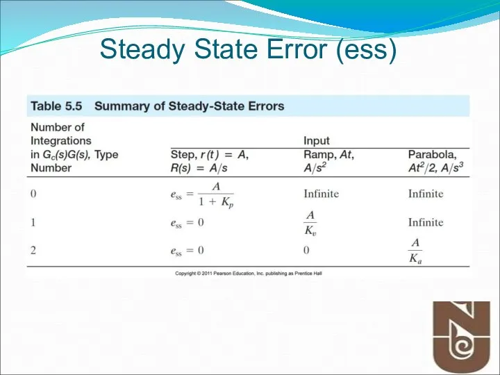
Steady State Error (ess)
Steady State Error (ess)
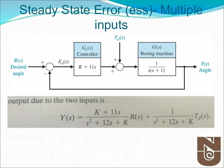
Steady State Error (ess)- Multiple inputs
Steady State Error (ess)- Multiple inputs
Classical Controller-
PID Controller
Classical Controller-
PID Controller
Introduction
More than half of the industrial controllers in use today utilize
Introduction
More than half of the industrial controllers in use today utilize
PID Control
A closed loop (feedback) control system, generally with Single Input-Single
PID Control
A closed loop (feedback) control system, generally with Single Input-Single
When PID Control is Used
PID control works well on SISO systems
When PID Control is Used
PID control works well on SISO systems
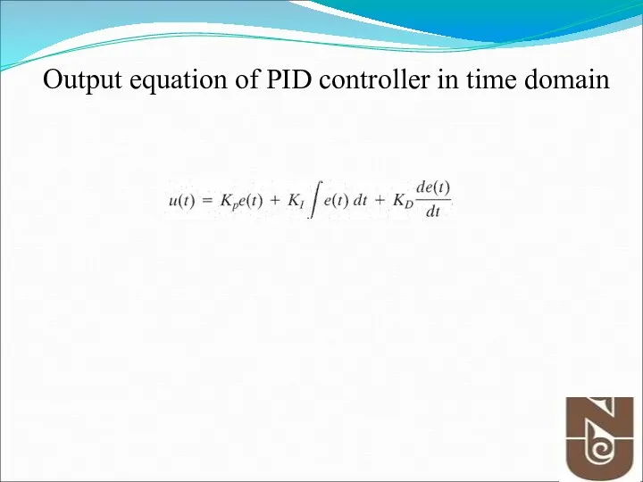
Output equation of PID controller in time domain
Output equation of PID controller in time domain
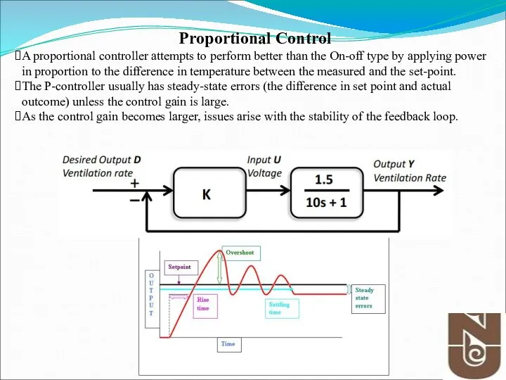
Proportional Control
A proportional controller attempts to perform better than the On-off
Proportional Control
A proportional controller attempts to perform better than the On-off
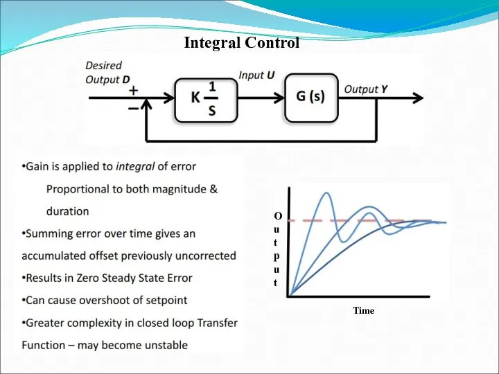
Integral Control
Time
Output
Integral Control
Time
Output
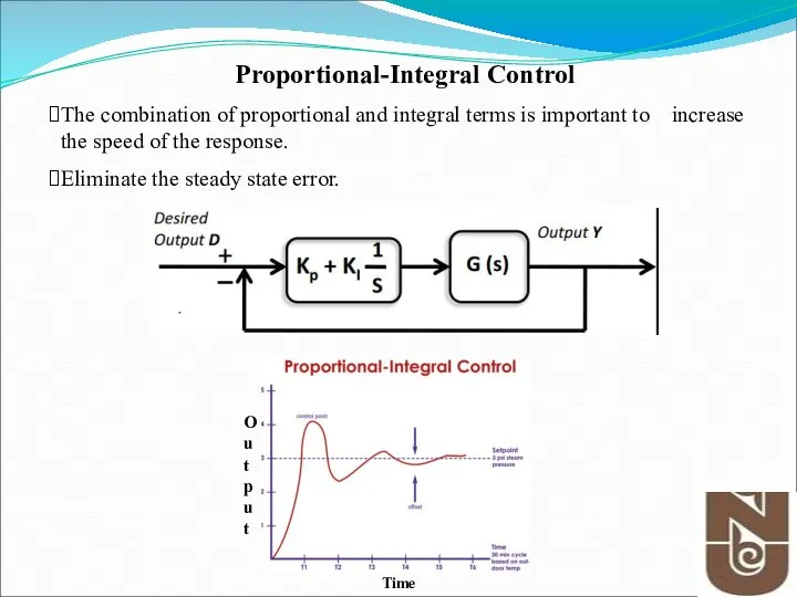
Proportional-Integral Control
The combination of proportional and integral terms is important to
Proportional-Integral Control
The combination of proportional and integral terms is important to
Tips for Designing a PID Controller
1. Obtain an open-loop response and determine
Tips for Designing a PID Controller
1. Obtain an open-loop response and determine
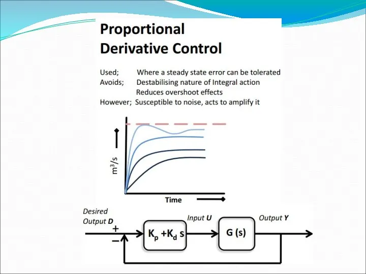
The Characteristics of P, I, and D controllers
A proportional controller (Kp)
The Characteristics of P, I, and D controllers
A proportional controller (Kp)
Proportional Control
By only employing proportional control, a steady state error occurs.
Proportional
Proportional Control
By only employing proportional control, a steady state error occurs.
Proportional
Tips for Designing a PID Controller
1. Obtain an open-loop response and determine
Tips for Designing a PID Controller
1. Obtain an open-loop response and determine
![num=1; den=[1 10 20]; step(num,den) Open-Loop Control - Example PID Controller (Conti… )](/_ipx/f_webp&q_80&fit_contain&s_1440x1080/imagesDir/jpg/1480480/slide-18.jpg)
num=1;
den=[1 10 20];
step(num,den)
Open-Loop Control - Example
PID Controller (Conti…
den=[1 10 20];
step(num,den)
Open-Loop Control - Example
PID Controller (Conti…
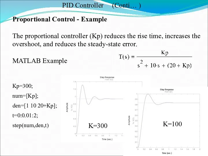
Proportional Control - Example
The proportional controller (Kp) reduces the rise time,
Proportional Control - Example
The proportional controller (Kp) reduces the rise time,
![Kp=300; Kd=10; num=[Kd Kp]; den=[1 10+Kd 20+Kp]; t=0:0.01:2; step(num,den,t) Proportional -](/_ipx/f_webp&q_80&fit_contain&s_1440x1080/imagesDir/jpg/1480480/slide-20.jpg)
Kp=300;
Kd=10;
num=[Kd Kp];
den=[1 10+Kd 20+Kp];
t=0:0.01:2;
step(num,den,t)
Proportional - Derivative - Example
The derivative controller (Kd)
Kp=300;
Kd=10;
num=[Kd Kp];
den=[1 10+Kd 20+Kp];
t=0:0.01:2;
step(num,den,t)
Proportional - Derivative - Example
The derivative controller (Kd)
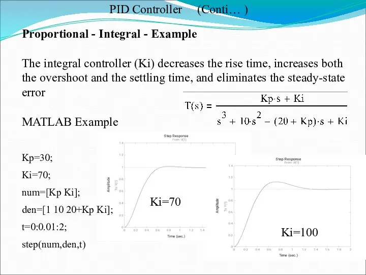
Proportional - Integral - Example
The integral controller (Ki) decreases the rise
Proportional - Integral - Example
The integral controller (Ki) decreases the rise
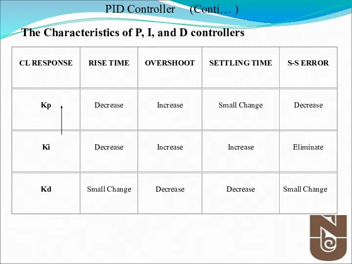
The Characteristics of P, I, and D controllers
PID Controller (Conti… )
The Characteristics of P, I, and D controllers
PID Controller (Conti… )
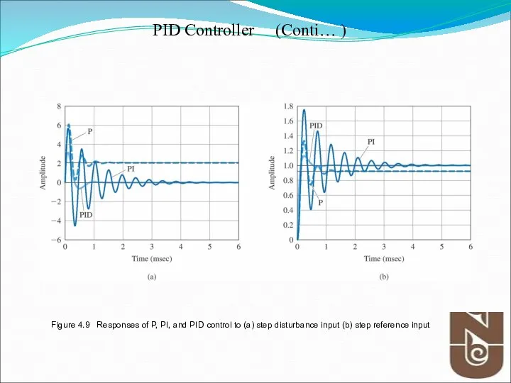
Figure 4.9 Responses of P, PI, and PID control to (a)
Figure 4.9 Responses of P, PI, and PID control to (a)
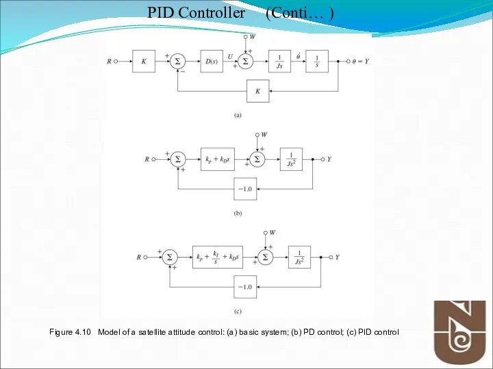
Figure 4.10 Model of a satellite attitude control: (a) basic system;
Figure 4.10 Model of a satellite attitude control: (a) basic system;
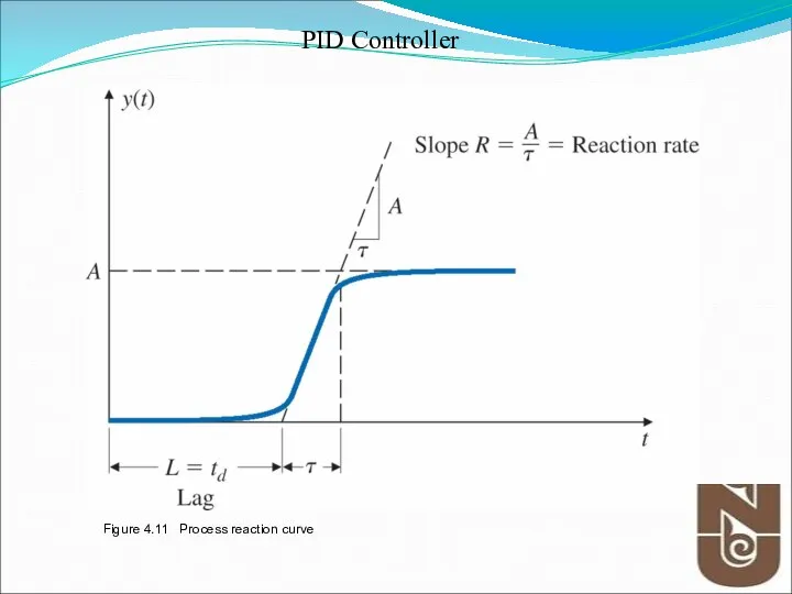
Figure 4.11 Process reaction curve
PID Controller
Figure 4.11 Process reaction curve
PID Controller
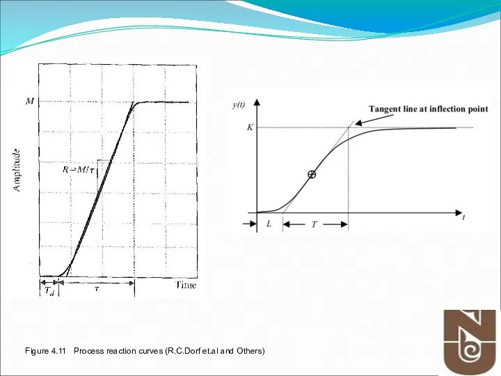
Figure 4.11 Process reaction curves (R.C.Dorf et.al and Others)
Figure 4.11 Process reaction curves (R.C.Dorf et.al and Others)
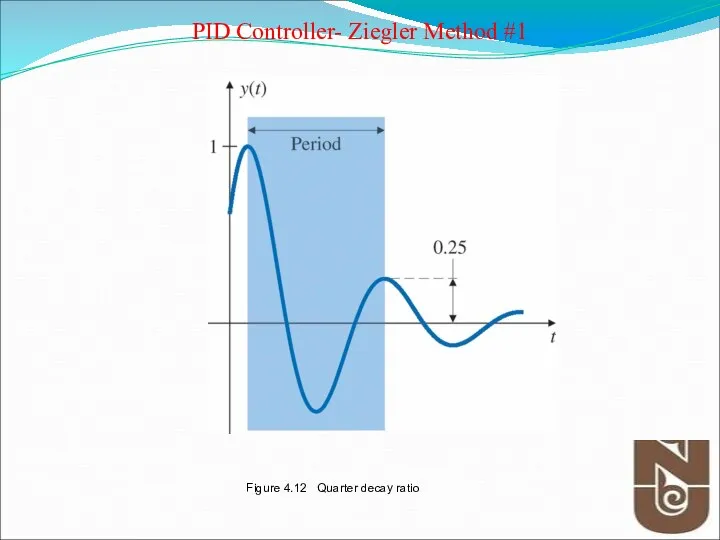
Figure 4.12 Quarter decay ratio
PID Controller- Ziegler Method #1
Figure 4.12 Quarter decay ratio
PID Controller- Ziegler Method #1
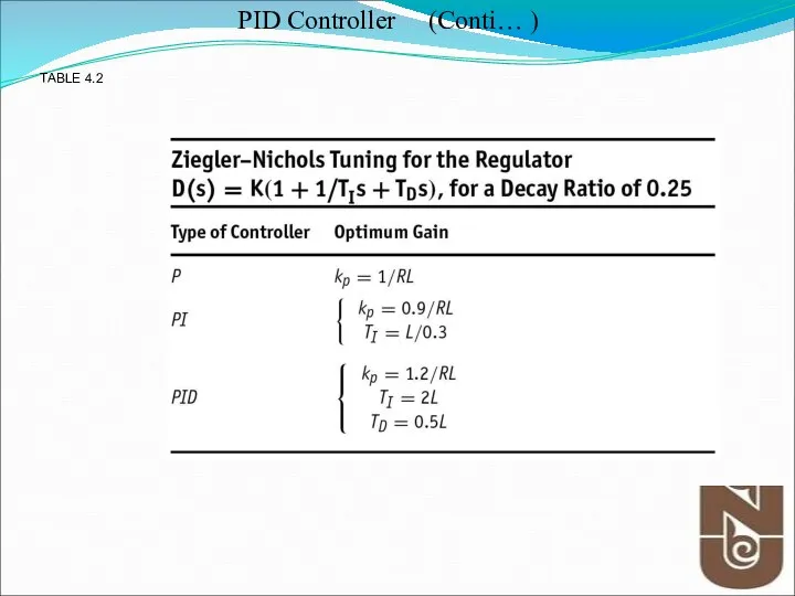
TABLE 4.2
PID Controller (Conti… )
TABLE 4.2
PID Controller (Conti… )
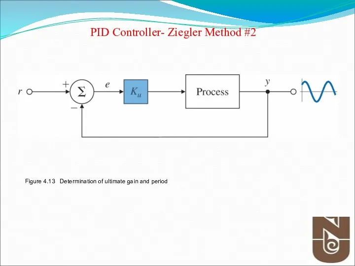
Figure 4.13 Determination of ultimate gain and period
PID Controller- Ziegler Method
Figure 4.13 Determination of ultimate gain and period
PID Controller- Ziegler Method
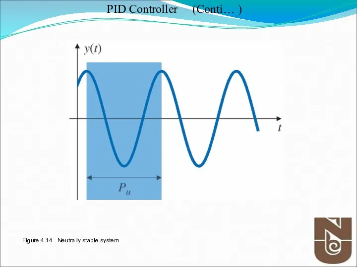
Figure 4.14 Neutrally stable system
PID Controller (Conti… )
Figure 4.14 Neutrally stable system
PID Controller (Conti… )
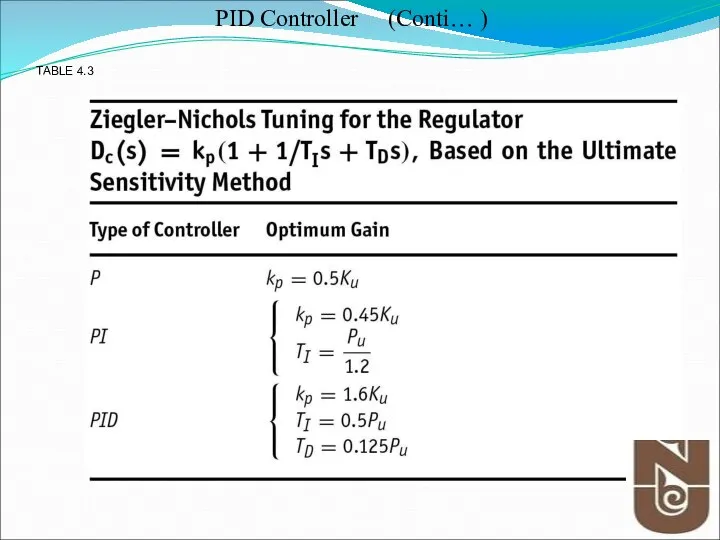
TABLE 4.3
PID Controller (Conti… )
TABLE 4.3
PID Controller (Conti… )
 Электропроводность диэлектриков
  Решение задач по теме «Законы Ньютона»
 Макарівський НВК Гучномовець Роботу виконав Учениця 11-а класу Макарівського НВК Заріцька Вікторія Вчитель Оладько В.К. 20
 Теплоизоляция домов
 Специальные вопросы электроснабжения. Изоляция и перенапряжения
 Импульс. Закон сохранения импульса. 9 класс
 Стримерлер - электрлік тесіп өтудің алдында атмосфералык қысым астында күшті электр өрісінде орналасқан газда кұралатын жіңішке
 Давление газа
 Проблемы современной физики
 Фізична картина світу та її роль у розвитку фізики Виконала учениця 33-ї групи Кулішова Інна
  Технология бурения горизонтальной скважины с применением роторной управляемой системы
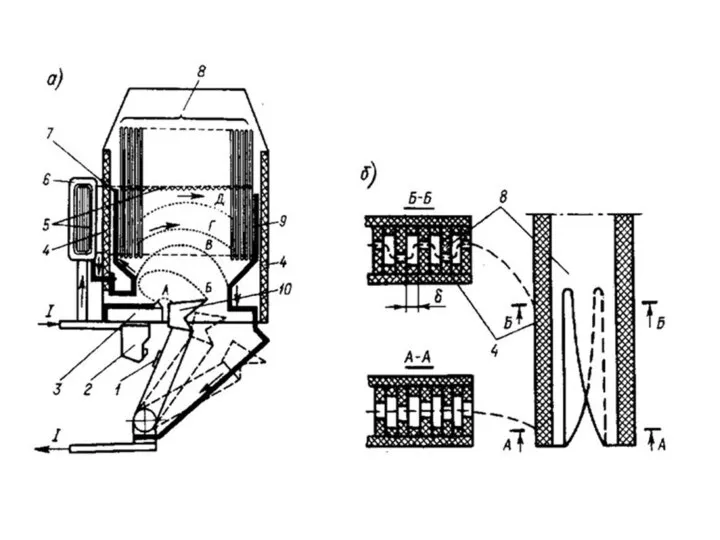 Выключатель ВМТ-110:
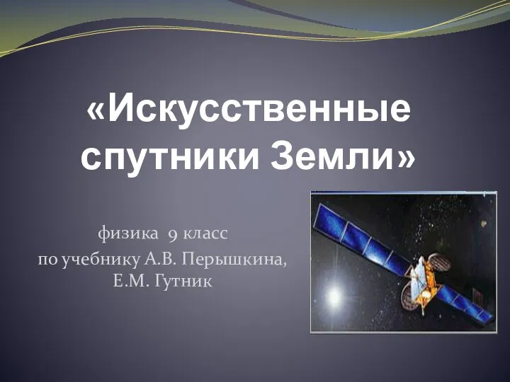 Искусственные спутники Земли ( 9 класс)
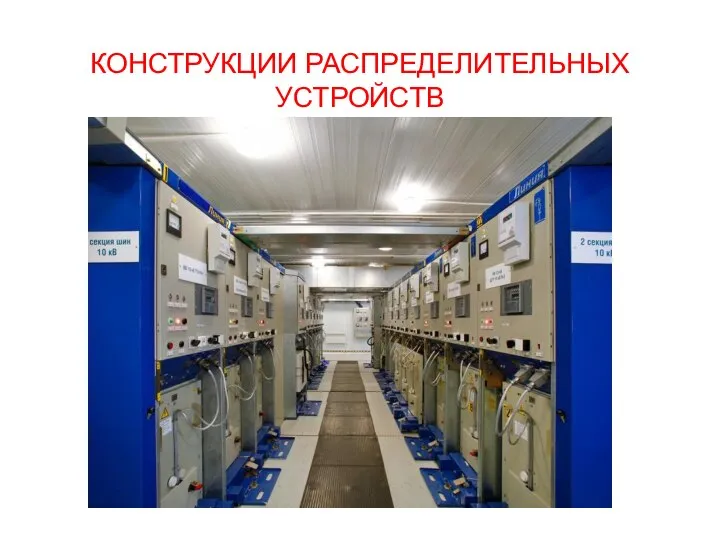 Конструкции распределительных устройств. (Лекция 15)
 Закони динаміки. Перший закон Ньютона. Інерціальні системи відліку
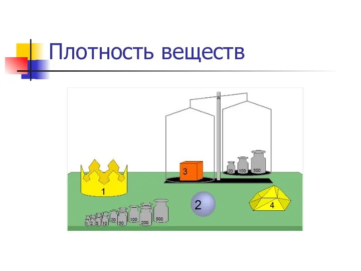 Плотность веществ
 Гравитация Всемирное тяготение Работу выполнила Ученица 8 «а» класса Гимназии №1 г. Миллерово Величко Анастасия Руководитель
  Geodesy. Modern geodetic technique
 Stress analysis versus modes of fracture in composites
 Взаимозаменяемость и система допусков и посадок. Исходные положения
 Электроэнергетика мира
  Диагностика, техническое обслуживание карданной передачи автомобиля ГАЗ-53 и технологический процесс замены изношенных крестовин
 Теплофизика. Теория теплообмена
 Конденсатори
  План лекции Конструкционные схемы и параметры ПГ с различными теплоносителями Конструкционные схемы Особенности схем с водным
  Нобелевская премия по физике
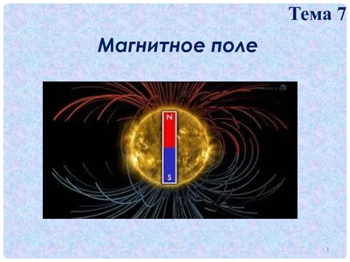 Магнитное поле. Тема 7
 Тайна мыльных пузырей