- Digital Logic Tutorial and Design

Содержание
- 2. Digital Logic Lab (A mini-lab experience) We are going to build both a combination lock and
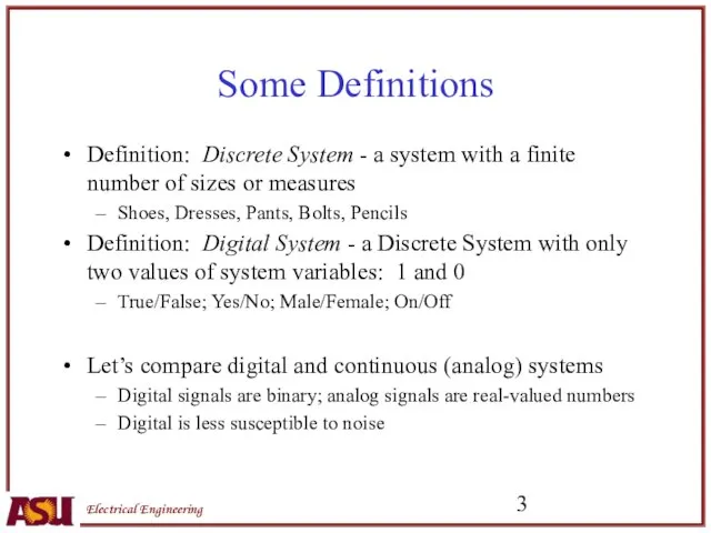
- 3. Some Definitions Definition: Discrete System - a system with a finite number of sizes or measures
- 4. 0 5 Analog Waveform Time Voltage (V) 0 5 Digital Waveform Time Voltage (V) 1 0
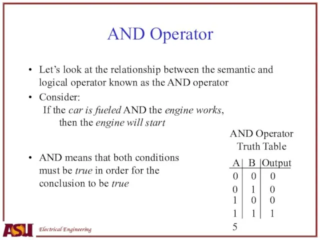
- 5. AND Operator Let’s look at the relationship between the semantic and logical operator known as the
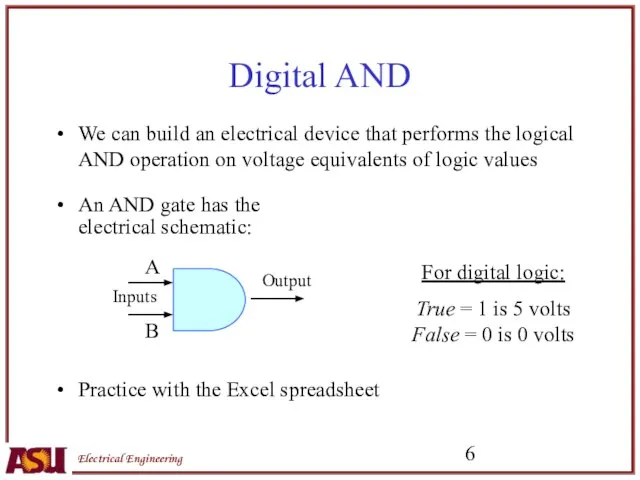
- 6. Digital AND We can build an electrical device that performs the logical AND operation on voltage
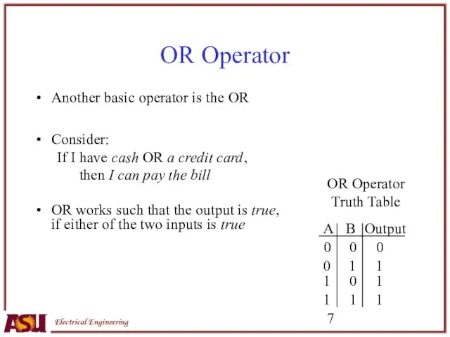
- 7. OR Operator Another basic operator is the OR Consider: If I have cash OR a credit
- 8. NOT Operator/Inverter Gate The NOT gate reverses the input NOT Operator Truth Table All digital computers
- 9. XOR (Exclusive OR) Operator Let’s look at the relationship between the semantic and logical operator known
- 10. Digital XOR We can build an electrical device that performs the logical XOR operation on voltage
- 11. Digital Combination Lock Design and Software Simulation
- 12. Multi-Input AND Gate AND gates can be built with any number of inputs Consider the symbol
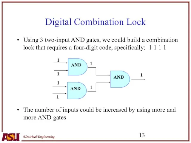
- 13. Digital Combination Lock Using 3 two-input AND gates, we could build a combination lock that requires
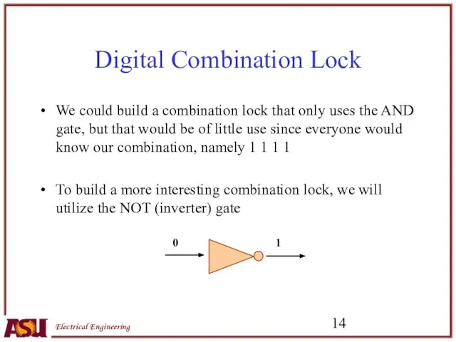
- 14. Digital Combination Lock We could build a combination lock that only uses the AND gate, but
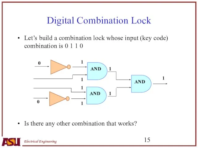
- 15. Digital Combination Lock Let’s build a combination lock whose input (key code) combination is 0 1
- 16. “Picking” a Digital Lock Use the truth table below to record the lock outputs for the
- 17. Digital Railroad Crossing Signal Design and Software Simulation
- 18. Digital Railroad Crossing Signal Now, let’s develop a digital circuit whose output changes over time We
- 19. Railroad Crossing Signal Design Here we will need some type of timing signal that will tell
- 20. Railroad Crossing Signal Turn-on voltage puts out a constant +5 volts Square wave is being repeatedly
- 22. Скачать презентацию

Digital Logic Lab
(A mini-lab experience)
We are going to build both a
Digital Logic Lab
(A mini-lab experience)
We are going to build both a
Some Definitions
Definition: Discrete System - a system with a finite number
Some Definitions
Definition: Discrete System - a system with a finite number

0
5
Analog Waveform
Time
Voltage (V)
0
5
Digital Waveform
Time
Voltage (V)
1
0
1
0
5
Analog Waveform
Time
Voltage (V)
0
5
Digital Waveform
Time
Voltage (V)
1
0
1
AND Operator
Let’s look at the relationship between the semantic and logical
AND Operator
Let’s look at the relationship between the semantic and logical
Digital AND
We can build an electrical device that performs the logical
Digital AND
We can build an electrical device that performs the logical
OR Operator
Another basic operator is the OR
Consider:
If I have cash OR
OR Operator
Another basic operator is the OR
Consider:
If I have cash OR
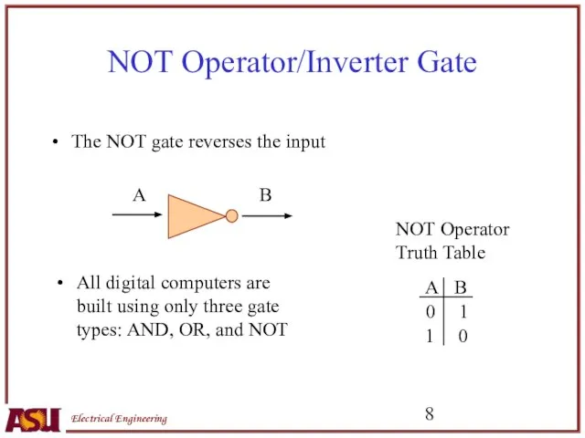
NOT Operator/Inverter Gate
The NOT gate reverses the input
NOT Operator
Truth Table
All digital
NOT Operator/Inverter Gate
The NOT gate reverses the input
NOT Operator
Truth Table
All digital
XOR (Exclusive OR) Operator
Let’s look at the relationship between the semantic
XOR (Exclusive OR) Operator
Let’s look at the relationship between the semantic
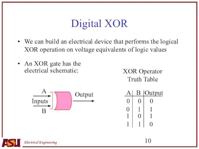
Digital XOR
We can build an electrical device that performs the logical
Digital XOR
We can build an electrical device that performs the logical
Digital Combination Lock
Design and Software Simulation
Digital Combination Lock
Design and Software Simulation

Multi-Input AND Gate
AND gates can be built with any number of
Multi-Input AND Gate
AND gates can be built with any number of
Digital Combination Lock
Using 3 two-input AND gates, we could build a
Digital Combination Lock
Using 3 two-input AND gates, we could build a
Digital Combination Lock
We could build a combination lock that only uses
Digital Combination Lock
We could build a combination lock that only uses
Digital Combination Lock
Let’s build a combination lock whose input (key code)
Digital Combination Lock
Let’s build a combination lock whose input (key code)

“Picking” a Digital Lock
Use the truth table below to record the
“Picking” a Digital Lock
Use the truth table below to record the

Digital Railroad Crossing Signal
Design and Software Simulation
Digital Railroad Crossing Signal
Design and Software Simulation

Digital Railroad Crossing Signal
Now, let’s develop a digital circuit whose output
Digital Railroad Crossing Signal
Now, let’s develop a digital circuit whose output

Railroad Crossing Signal Design
Here we will need some type of timing
Railroad Crossing Signal Design
Here we will need some type of timing

Railroad Crossing Signal
Turn-on voltage puts out a constant +5 volts
Square wave
Railroad Crossing Signal
Turn-on voltage puts out a constant +5 volts
Square wave
 Технология работы с графической информацией в редакторе презентаций
 PowerPoint Программа для создания презентаций
 Презентация "ВРЕМЯ И ЧИСЛОВАЯ ИНФОРМАЦИЯ (2 КЛАСС)" - скачать презентации по Информатике
 ЕГЭ 2012 Информатика и ИКТ Консультация №4
  Проектирование базы данных
 Проектирование GetCI & FaU
 Защита программного обеспечения от реверс-инжиниринга
 Основы информационной безопасности
 Интернет в жизни старшеклассников: за и против
 Программирование на языке C++
 Презентация "Двоичный код" - скачать презентации по Информатике
 Проектирование локальных сетей второго и третьего уровней. (Лекция 1)
 Стратегия 2016 года. Инструкция
 Структурное программирование Особенности работы с функциями
 Общие принципы построения ЭВМ
 Алгоритмизация и программирование. Типовые алгоритмы решения задач
 Software
 Lietvedība Arhīvs
 Web of science. Мировая практика применения индекса цитирования при проведении научных исследований
 Презентация "Алгоритм как модель деятельности" - скачать презентации по Информатике
 Презентация "Кодирование информации с помощью знаковых систем" - скачать презентации по Информатике
 Информационные модели на графах. Введение
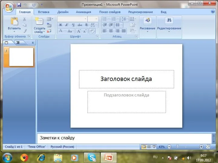 Анимация объектов. Microsoft PowerPoint
 Управление и кибернетика. Алгоритм и его свойства. Алгоритмические структуры. Графический учебный исполнитель. Тест № 3 для 9 к
 Створення таблиць, форм, запитів і звітів
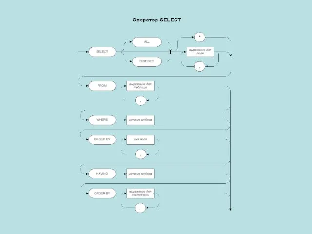 Схема построения запросов SQL
 Оперативная картография
 Проектирование информационных систем. Промышленные технологии