- Site graphics. Graphical alarm management system

Содержание
- 2. Cooper Site Graphics Graphical aid to manage alarm activations Programmable to suit any application Hospitals, universities,
- 3. Cooper Site Graphics Secure System Multiple Users and Multiple PC Workstations Image, Plan or Text Displays
- 4. System Application Large industrial or commercial sites Critical safety requirements Multiple building projects Introduction
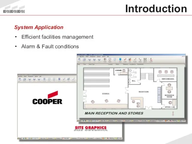
- 5. System Application Efficient facilities management Alarm & Fault conditions Introduction
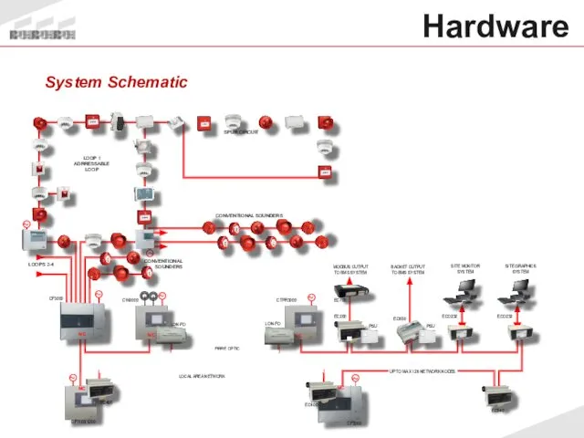
- 6. Hardware System Schematic
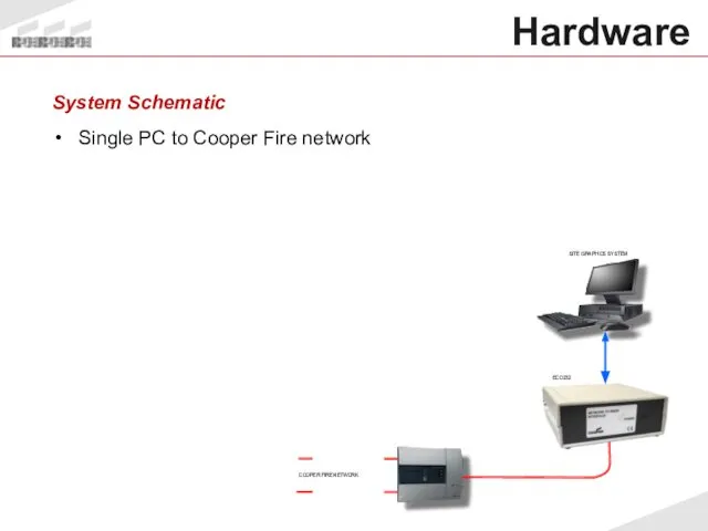
- 7. Hardware System Schematic Single PC to Cooper Fire network
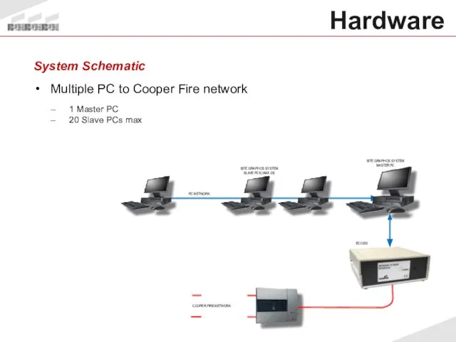
- 8. Hardware System Schematic Multiple PC to Cooper Fire network 1 Master PC 20 Slave PCs max
- 9. EC0232 Connections LON to RS232 converter Cooper Network to PC conversion hardware Requires 230V AC supply
- 10. Requirements Coded Dongle Serial Number, Client ID, any additional options Supplied with each software package Not
- 11. Hardware Minimum PC Spec Intel Pentium 2GHz or equivalent Windows 2000 SP4 Windows XP Professional SP2
- 12. Operation Functionality Device Events Device text transmitted by control panel Trigger device alarm or fault to
- 13. Network Manager Parameters Baud Rate: 4800 Parity: None Stop Bits: 1 Network Mon: 0 Comm Port:
- 14. Network Network Manager Test Box Engineer / Network Manager / Show Test Box Count increases if
- 15. Operation Getting Started PC Graphics 1024 x 768 Large Font Display Properties / Settings / Advanced
- 16. Operation Graphics Format BMP preferred, GIF, JPG, WMG also acceptable 1004 x 556 pixel Preparation Export
- 17. Setup of Input States Program Inputs Event types Input alarm pages template Reset Page template Assign
- 18. Symbols Simple Symbols 2 pictures for ON and OFF state of device Compound Symbols 17 pictures
- 19. Operator Access 2000 users max Unique pass-code Profile Definition of access rights Operation
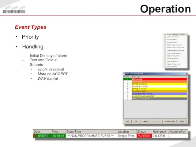
- 20. Operation Event Types Priority Handling Initial Display of alarm Text and Colour Sounds single or repeat
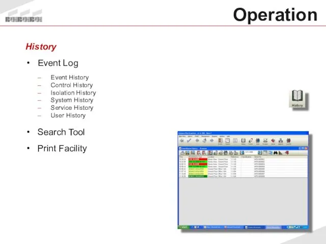
- 21. Operation History Event Log Event History Control History Isolation History System History Service History User History
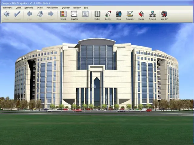
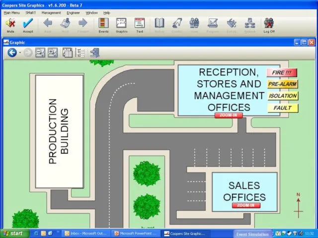
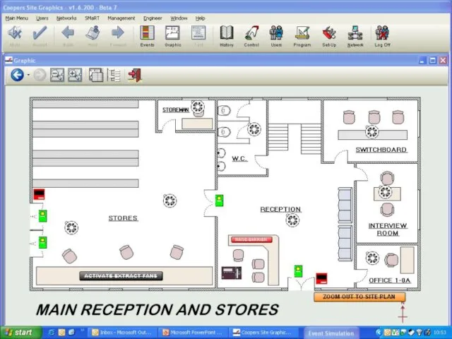
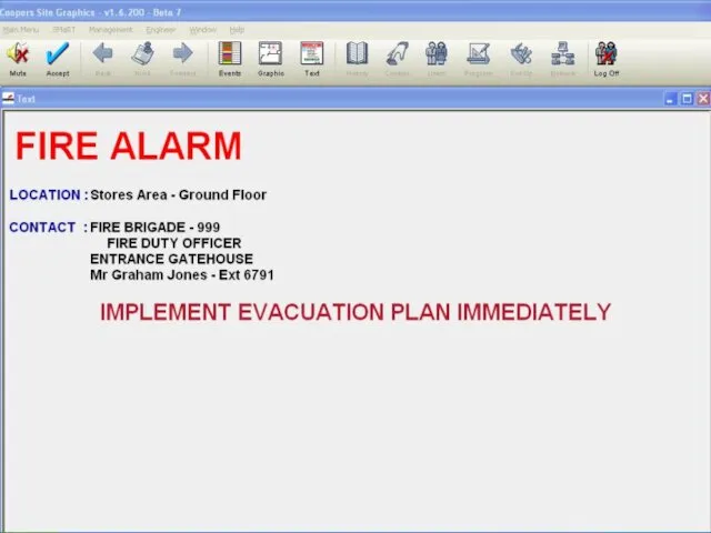
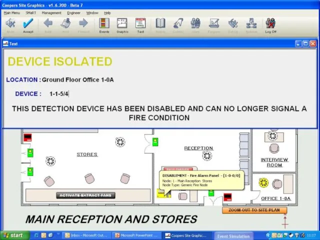
- 22. Examples Sample Screens Site Image Site Plan Floor Plan Text Screens Combined Screens
- 26. Operation Example Typical System
- 28. Start Communications Prepare Maps and import Assign Graphics Add Symbols Use Dialogue Box to test maps
- 29. Operation Fault Finding No Communication Check Network Text Box for comms Configure Network Manager Insert Dongle
- 31. Скачать презентацию
Cooper Site Graphics
Graphical aid to manage alarm activations
Programmable to suit any
Cooper Site Graphics
Graphical aid to manage alarm activations
Programmable to suit any
Cooper Site Graphics
Secure System
Multiple Users and Multiple PC Workstations
Image, Plan or
Cooper Site Graphics
Secure System
Multiple Users and Multiple PC Workstations
Image, Plan or
System Application
Large industrial or commercial sites
Critical safety requirements
Multiple building projects
Introduction
System Application
Large industrial or commercial sites
Critical safety requirements
Multiple building projects
Introduction
System Application
Efficient facilities management
Alarm & Fault conditions
Introduction
System Application
Efficient facilities management
Alarm & Fault conditions
Introduction
Hardware
System Schematic
Hardware
System Schematic
Hardware
System Schematic
Single PC to Cooper Fire network
Hardware
System Schematic
Single PC to Cooper Fire network
Hardware
System Schematic
Multiple PC to Cooper Fire network
1 Master PC
20 Slave
Hardware
System Schematic
Multiple PC to Cooper Fire network
1 Master PC
20 Slave
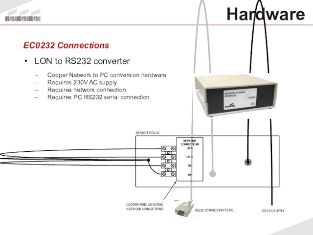
EC0232 Connections
LON to RS232 converter
Cooper Network to PC conversion hardware
Requires 230V
EC0232 Connections
LON to RS232 converter
Cooper Network to PC conversion hardware
Requires 230V
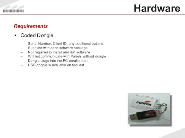
Requirements
Coded Dongle
Serial Number, Client ID, any additional options
Supplied with each software
Requirements
Coded Dongle
Serial Number, Client ID, any additional options
Supplied with each software
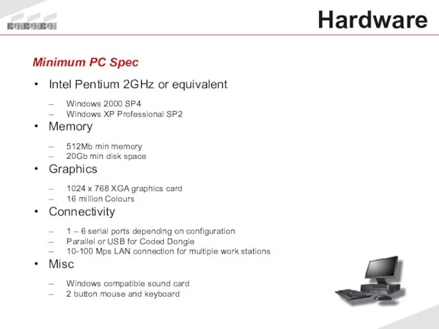
Hardware
Minimum PC Spec
Intel Pentium 2GHz or equivalent
Windows 2000 SP4
Windows XP
Hardware
Minimum PC Spec
Intel Pentium 2GHz or equivalent
Windows 2000 SP4
Windows XP
Operation
Functionality
Device Events
Device text transmitted by control panel
Trigger device alarm or
Operation
Functionality
Device Events
Device text transmitted by control panel
Trigger device alarm or
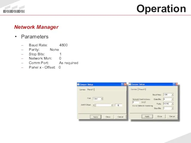
Network Manager
Parameters
Baud Rate: 4800
Parity: None
Stop Bits: 1
Network Mon: 0
Comm Port: As
Network Manager
Parameters
Baud Rate: 4800
Parity: None
Stop Bits: 1
Network Mon: 0
Comm Port: As
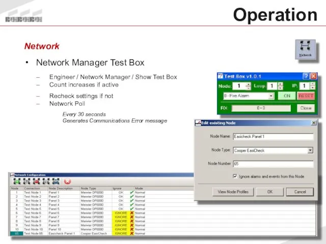
Network
Network Manager Test Box
Engineer / Network Manager / Show Test Box
Count
Network
Network Manager Test Box
Engineer / Network Manager / Show Test Box
Count
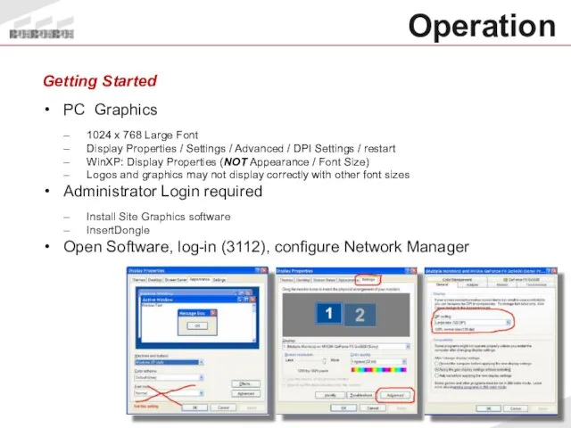
Operation
Getting Started
PC Graphics
1024 x 768 Large Font
Display Properties / Settings
Operation
Getting Started
PC Graphics
1024 x 768 Large Font
Display Properties / Settings
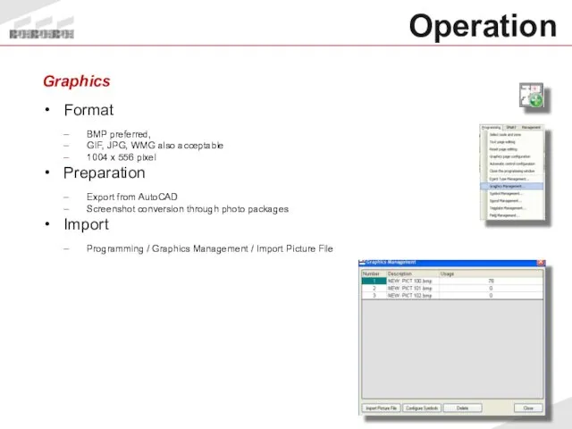
Operation
Graphics
Format
BMP preferred,
GIF, JPG, WMG also acceptable
1004 x 556 pixel
Preparation
Export from
Operation
Graphics
Format
BMP preferred,
GIF, JPG, WMG also acceptable
1004 x 556 pixel
Preparation
Export from
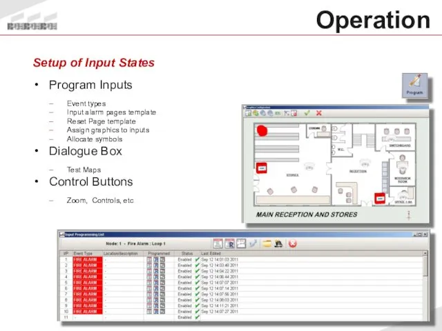
Setup of Input States
Program Inputs
Event types
Input alarm pages template
Reset Page template
Assign
Setup of Input States
Program Inputs
Event types
Input alarm pages template
Reset Page template
Assign
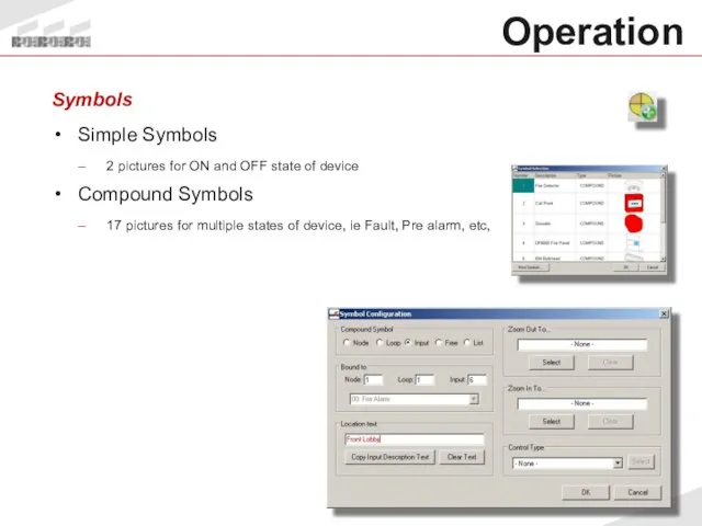
Symbols
Simple Symbols
2 pictures for ON and OFF state of device
Compound Symbols
17
Symbols
Simple Symbols
2 pictures for ON and OFF state of device
Compound Symbols
17
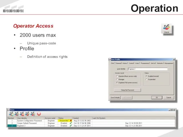
Operator Access
2000 users max
Unique pass-code
Profile
Definition of access rights
Operation
Operator Access
2000 users max
Unique pass-code
Profile
Definition of access rights
Operation
Operation
Event Types
Priority
Handling
Initial Display of alarm
Text and Colour
Sounds
single or repeat
Mute on
Operation
Event Types
Priority
Handling
Initial Display of alarm
Text and Colour
Sounds
single or repeat
Mute on
Operation
History
Event Log
Event History
Control History
Isolation History
System History
Service History
User History
Search Tool
Print Facility
Operation
History
Event Log
Event History
Control History
Isolation History
System History
Service History
User History
Search Tool
Print Facility
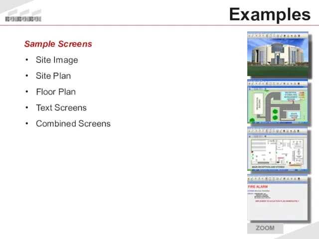
Examples
Sample Screens
Site Image
Site Plan
Floor Plan
Text Screens
Combined Screens
Examples
Sample Screens
Site Image
Site Plan
Floor Plan
Text Screens
Combined Screens
Operation
Example
Typical System
Operation
Example
Typical System
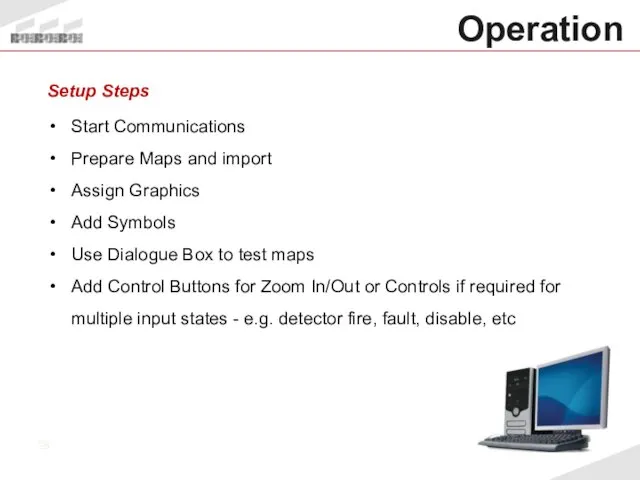
Start Communications
Prepare Maps and import
Assign Graphics
Add Symbols
Use Dialogue Box to test
Start Communications
Prepare Maps and import
Assign Graphics
Add Symbols
Use Dialogue Box to test
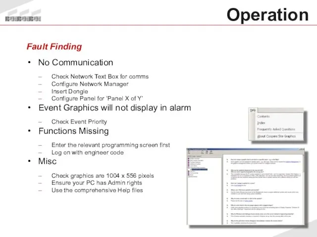
Operation
Fault Finding
No Communication
Check Network Text Box for comms
Configure Network Manager
Insert
Operation
Fault Finding
No Communication
Check Network Text Box for comms
Configure Network Manager
Insert
 Устройства ввода и вывода информации
 Электронная почта
 Основы логики и логические основы компьютера
 Структура программы на языке Паскаль
 Презентация "Выполнение алгоритмов для исполнителя (А18)" - скачать презентации по Информатике
 Расширенные параметры протокола OSPF для одной области
 Автоматизация бизнес-процессов с RPA
 Формирование изображения на экране монитора
 Podmínky kurzu Vývojové prostředí NetBeans
 Создание фракталов с помощью компьютерных программ
 Детерминантты шекті автоматтар. Мур диаграммасы
 Cmpe 466 computer graphics. Computer graphics software. (Chapter 3)
 Системи управління базами даних Access
 Моделирование как метод познания. 11 класс
 Объекты компьютерной графики
 Презентация на тему Кодирование графической информации Пространственная дискретизация 9 класс
 Системы счисления
 Одномерные массивы целых чисел
 Дистанційне навчання
 Электронные способы общения, их актуальность, использование в профессиональной деятельности
 Базы данных. Основные понятия баз данных и СУБД
 Мультимедиа
 Семинар Умный дом. Обзор системы KNX
 Поддержка социальной и творческой активности педагогов средствами сетевых сервисов Web 2.0
 Blender. Метод выдавливания полигонов. Инструмент подразделения Subdivide
 Автоматизация стратегических задач планирования и управления
 Домен и хостинг. Как сделать правильный выбор
 Язык С++. Операторы преобразования типов