- Advanced Design Lab: CCD History

Содержание
- 2. Activities in 1980-2005 Development of four generations of CCD Controllers Development of LN2 Cameras for various
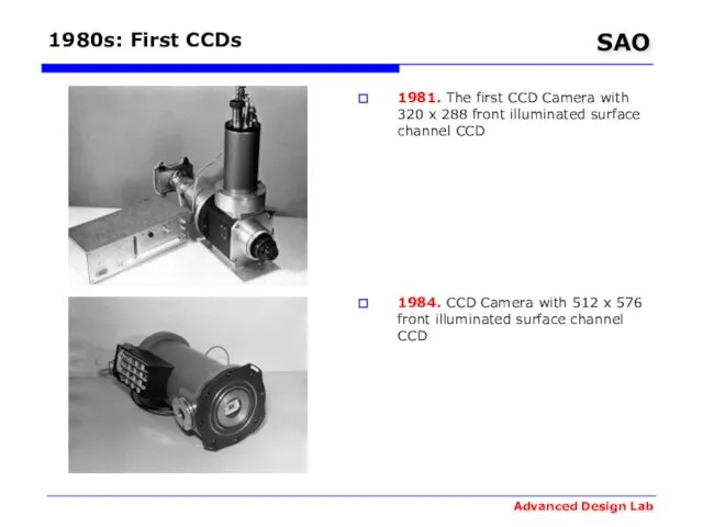
- 3. 1980s: First CCDs 1981. The first CCD Camera with 320 x 288 front illuminated surface channel
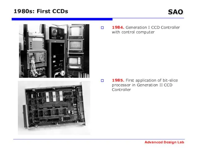
- 4. 1980s: First CCDs 1984. Generation I CCD Controller with control computer 1985. First application of bit-slice
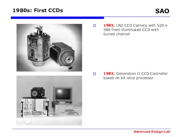
- 5. 1980s: First CCDs 1985. LN2 CCD Camera with 520 x 580 front illuminated CCD with buried
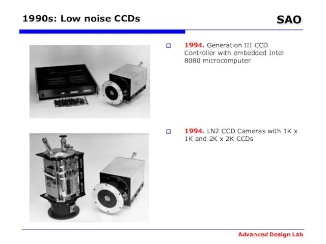
- 6. 1990s: Low noise CCDs 1994. Generation III CCD Controller with embedded Intel 8080 microcomputer 1994. LN2
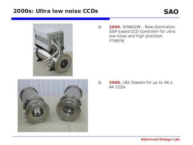
- 7. 2000s: Ultra low noise CCDs 2000. DINACON - New Generation DSP based CCD Controller for ultra
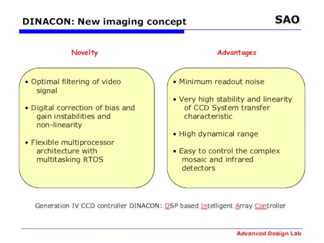
- 8. DINACON: New imaging concept Optimal filtering of video signal Digital correction of bias and gain instabilities
- 9. Titanium LN2 dewar with 90mm quartz glass window CCD-controller unit configured to operate 2K x 2K
- 10. Typical single processor CCD-system
- 11. SAO’s DSP-based CCD-system
- 12. Why need matched filtering? 1/f noise: matched filtering is up to 30 % more effective than
- 13. DINACON: Photometric results Readout noise reduction: 2.5 e → 1.7 e Photometric instability: 0.03% / 24
- 14. DINACON: CCD 42-40 noise ADU = 0.5 e Readout rate = 18 kHz Noise = 1.7
- 15. DINACON: The best noise SAO’s CCD 42-40
- 16. Scientific CCDs Noise
- 17. DINACON: Overscan instability
- 18. DINACON: Gain instability Gain instability at 1620 electrons level measured by means of Fe55
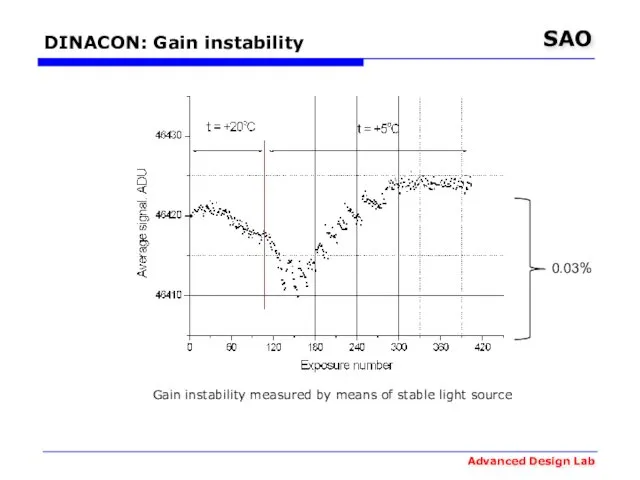
- 19. DINACON: Gain instability 0.03% Gain instability measured by means of stable light source
- 20. DINACON: Nonlinearity correction
- 21. DINACON: Instabilities on telescope
- 22. Buffington et al, 1990: 0.8% p-p Conditions: stabilized temperature Robinson et al,1995: 0.6% p-p Conditions: room
- 23. DINACON: Long-term bias instability ADU=0.5e‾ Instability during 6 monthes is about 1 electron p-p
- 24. ESO’s FIERA: Long-term bias instability ADU=2e‾ Instability during 8 monthes is about 60 electrons p-p
- 25. CCD Controllers Comparison
- 26. CCD Controllers Comparison
- 27. DINACON I Module Structure System controller with communication adapter Sequencer with drivers Videoprocessor Peripheral controller
- 28. DINACON I: Videoprocessor 32 bit DSP 40 MIPS Two 14 bit ADCs 10 MHz CCD’s output
- 29. DINACON I: Sequencer 32 bit DSP 40 MIPS Telemetry unit with 16 bit ADC Mezzanine connector
- 30. DINACON I: Clock drivers 4 CCD clocks unit # 1 4 CCD clocks Unit #6
- 31. DINACON I: System controller 32 bit DSP 40 MIPS 10 Mbit/s Ethernet mezzanine
- 32. DINACON I: Periferal controller 16 bit DSP 40 MIPS CAN bus controller CAN bus interface RS232
- 33. DINASYS: Control Sofware
- 34. DINACON II
- 35. DINACON II Module Structure System controller with communication adapter Sequencer with drivers Videoprocessor
- 36. DINACON II: Sequencer CCD clock drivers Telemetry unit with 16 bit ADC 12 bit DAC 32
- 37. DINACON II: Videoprocessor CCD’s output nodes control unit 12 bit DAC 32 channels 32 bit DSP
- 38. DINACON II: System controller 100 Mbit/s Ethernet controller 16 bit DSP 600 MIPS 256 MB SDRAM
- 39. DINACON DINASYS 2K x 2K on multi-pupil fiber spectrograph MPFS
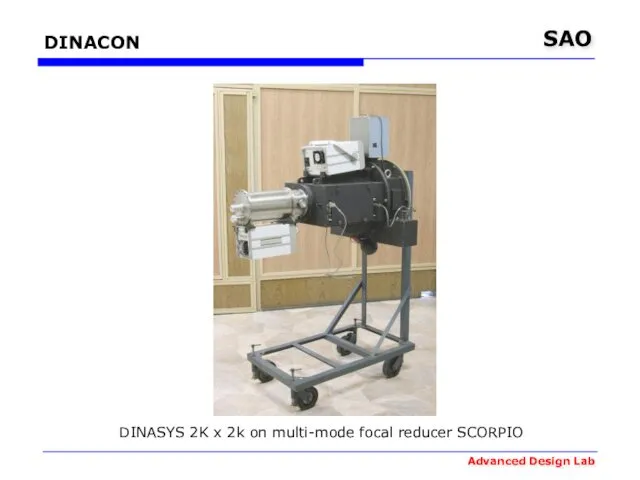
- 40. DINACON DINASYS 2K x 2k on multi-mode focal reducer SCORPIO
- 41. DINACON III Camera 2K x 4.5k and controller (without power supply)
- 42. Our team
- 43. DINACON III block diagram Main components: System controller 1 Gbit fiber-optic link Camera electronics
- 44. Camera Electronics block diagram
- 45. System controller block diagram
- 46. ADLab’s resources 2D and 3D computer aided design of CCD systems with release of full design
- 47. ADLab’s resources Detailed mathematical model construction of signals formation and processing for minimization of distortions, noise
- 48. ADLab’s resources Development of embedded software for digital signal processors Development of multitasking real-time kernels for
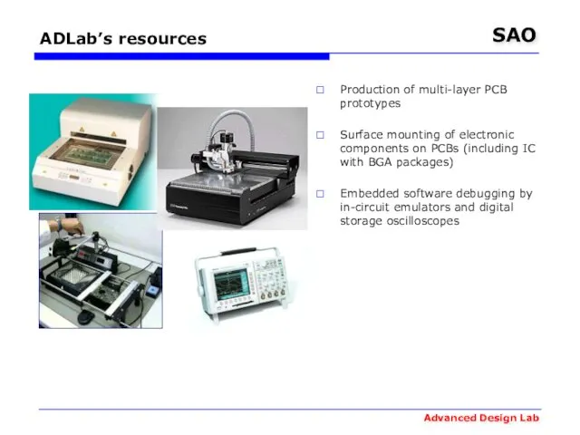
- 49. ADLab’s resources Production of multi-layer PCB prototypes Surface mounting of electronic components on PCBs (including IC
- 51. Скачать презентацию
Activities in 1980-2005
Development of four generations of CCD Controllers
Development of LN2
Activities in 1980-2005
Development of four generations of CCD Controllers
Development of LN2
1980s: First CCDs
1981. The first CCD Camera with 320 x 288
1980s: First CCDs
1981. The first CCD Camera with 320 x 288
1980s: First CCDs
1984. Generation I CCD Controller with control computer
1985. First
1980s: First CCDs
1984. Generation I CCD Controller with control computer
1985. First
1980s: First CCDs
1985. LN2 CCD Camera with 520 x 580 front
1980s: First CCDs
1985. LN2 CCD Camera with 520 x 580 front
1990s: Low noise CCDs
1994. Generation III CCD Controller with embedded Intel
1990s: Low noise CCDs
1994. Generation III CCD Controller with embedded Intel
2000s: Ultra low noise CCDs
2000. DINACON - New Generation DSP based
2000s: Ultra low noise CCDs
2000. DINACON - New Generation DSP based
DINACON: New imaging concept
Optimal filtering of video
signal
Digital correction
DINACON: New imaging concept
Optimal filtering of video
signal
Digital correction

Titanium LN2 dewar with 90mm quartz glass window
CCD-controller unit configured to
Titanium LN2 dewar with 90mm quartz glass window
CCD-controller unit configured to
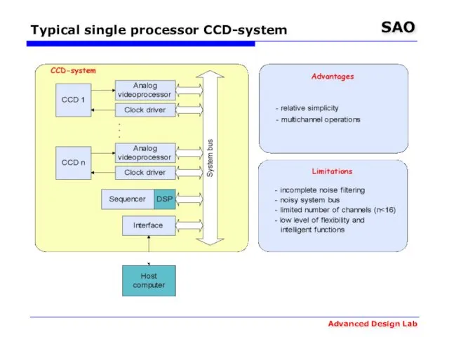
Typical single processor CCD-system
Typical single processor CCD-system
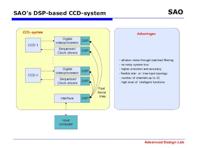
SAO’s DSP-based CCD-system
SAO’s DSP-based CCD-system
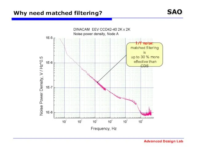
Why need matched filtering?
1/f noise:
matched filtering is
up to 30
Why need matched filtering?
1/f noise:
matched filtering is
up to 30
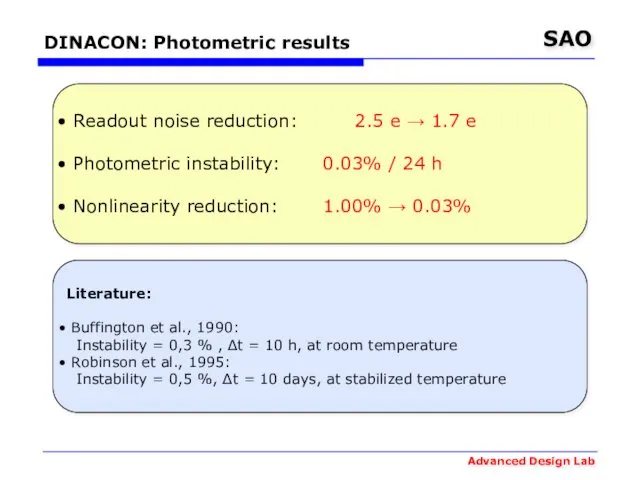
DINACON: Photometric results
Readout noise reduction: 2.5 e → 1.7 e
Photometric
DINACON: Photometric results
Readout noise reduction: 2.5 e → 1.7 e
Photometric
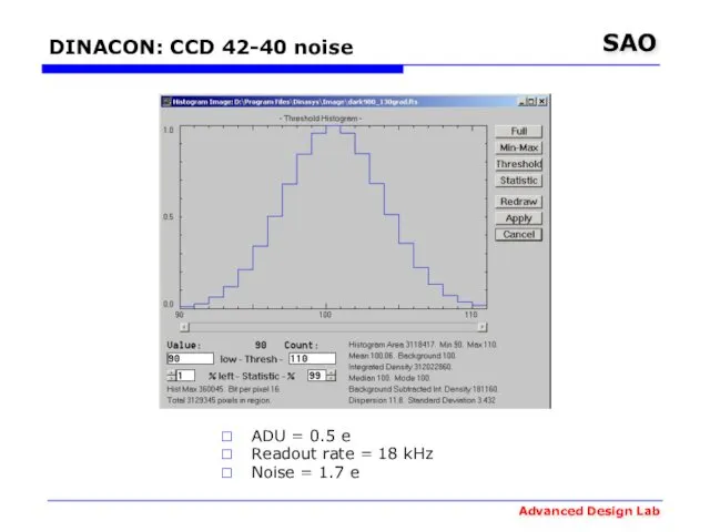
DINACON: CCD 42-40 noise
ADU = 0.5 e
Readout rate = 18 kHz
Noise
DINACON: CCD 42-40 noise
ADU = 0.5 e
Readout rate = 18 kHz
Noise
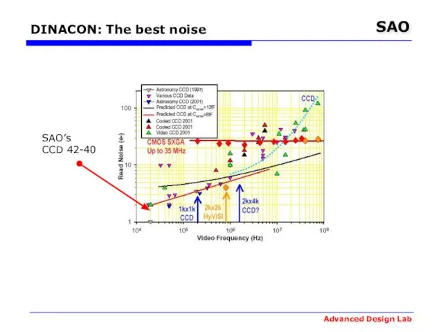
DINACON: The best noise
SAO’s
CCD 42-40
DINACON: The best noise
SAO’s
CCD 42-40
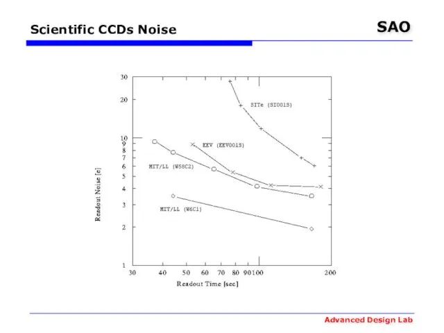
Scientific CCDs Noise
Scientific CCDs Noise
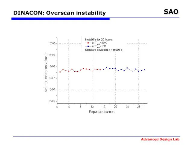
DINACON: Overscan instability
DINACON: Overscan instability
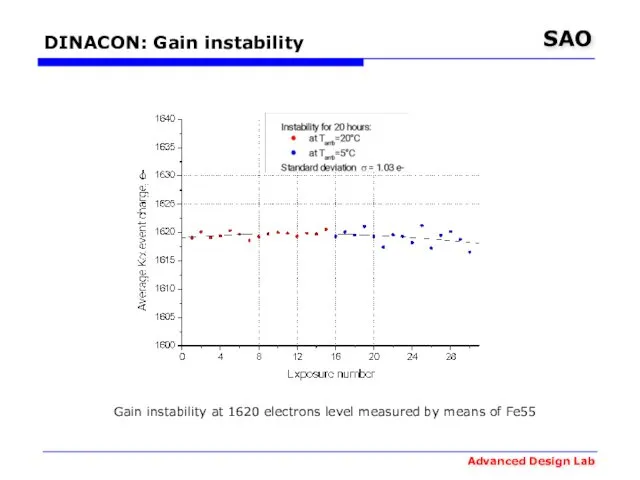
DINACON: Gain instability
Gain instability at 1620 electrons level measured by
DINACON: Gain instability
Gain instability at 1620 electrons level measured by
DINACON: Gain instability
0.03%
Gain instability measured by means of stable light source
DINACON: Gain instability
0.03%
Gain instability measured by means of stable light source
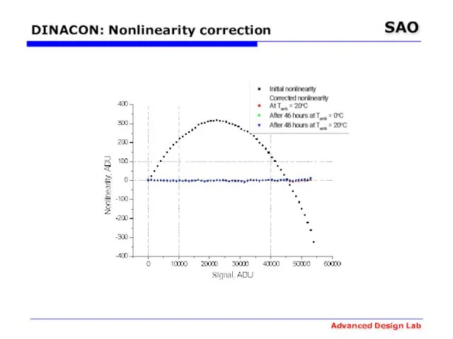
DINACON: Nonlinearity correction
DINACON: Nonlinearity correction
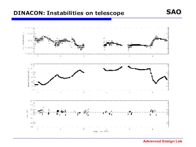
DINACON: Instabilities on telescope
DINACON: Instabilities on telescope
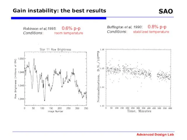
Buffington et al, 1990: 0.8% p-p
Conditions: stabilized temperature
Robinson et al,1995: 0.6%
Buffington et al, 1990: 0.8% p-p
Conditions: stabilized temperature
Robinson et al,1995: 0.6%
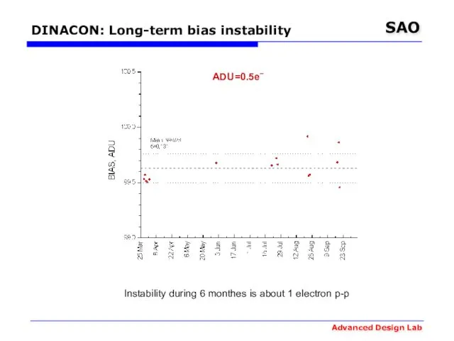
DINACON: Long-term bias instability
ADU=0.5e‾
Instability during 6 monthes is about 1 electron
DINACON: Long-term bias instability
ADU=0.5e‾
Instability during 6 monthes is about 1 electron
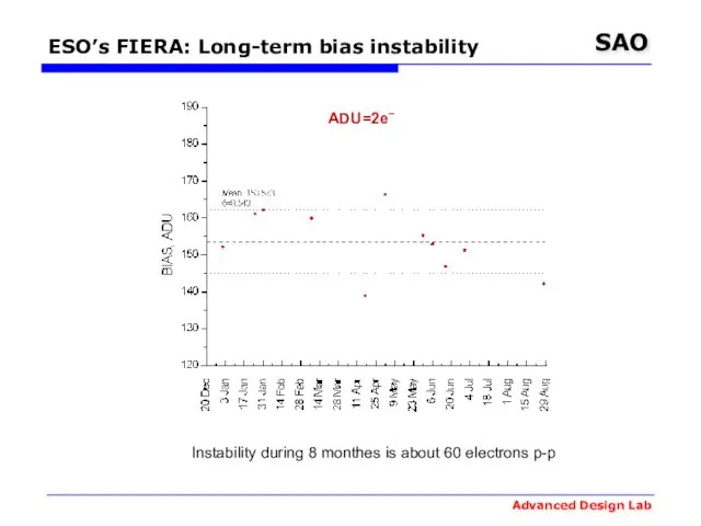
ESO’s FIERA: Long-term bias instability
ADU=2e‾
Instability during 8 monthes is about 60
ESO’s FIERA: Long-term bias instability
ADU=2e‾
Instability during 8 monthes is about 60
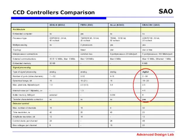
CCD Controllers Comparison
CCD Controllers Comparison
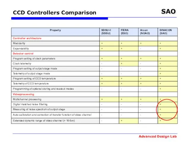
CCD Controllers Comparison
CCD Controllers Comparison
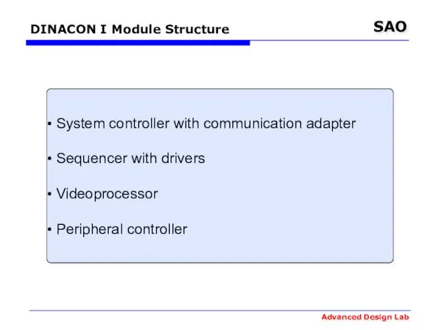
DINACON I Module Structure
System controller with communication adapter
Sequencer with
DINACON I Module Structure
System controller with communication adapter
Sequencer with
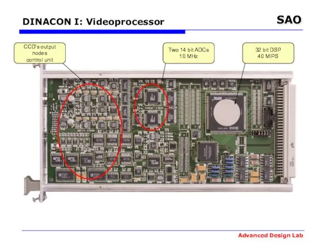
DINACON I: Videoprocessor
32 bit DSP
40 MIPS
Two 14 bit ADCs
10 MHz
CCD’s output
DINACON I: Videoprocessor
32 bit DSP
40 MIPS
Two 14 bit ADCs
10 MHz
CCD’s output
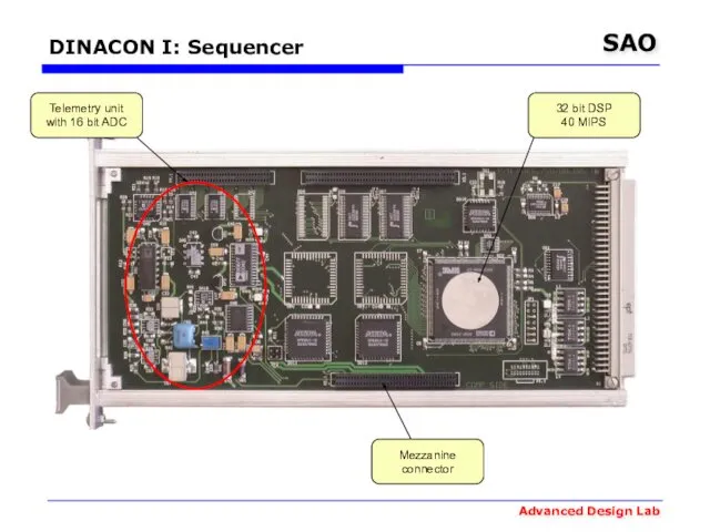
DINACON I: Sequencer
32 bit DSP
40 MIPS
Telemetry unit
with 16 bit ADC
Mezzanine
connector
DINACON I: Sequencer
32 bit DSP
40 MIPS
Telemetry unit
with 16 bit ADC
Mezzanine
connector
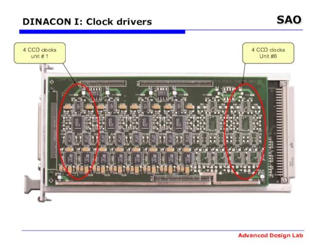
DINACON I: Clock drivers
4 CCD clocks
unit # 1
4 CCD clocks
Unit #6
DINACON I: Clock drivers
4 CCD clocks
unit # 1
4 CCD clocks
Unit #6
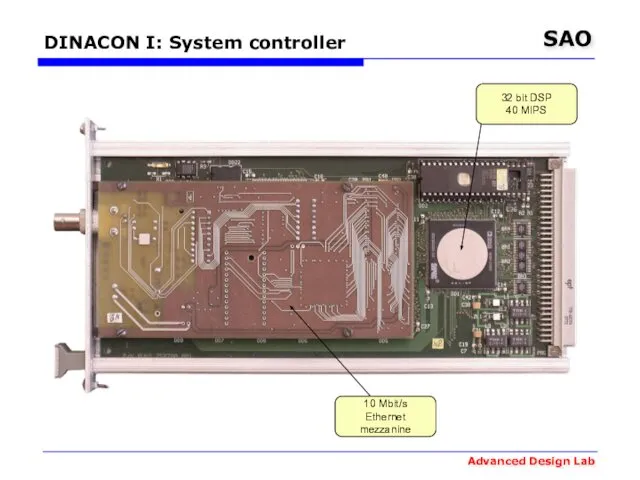
DINACON I: System controller
32 bit DSP
40 MIPS
10 Mbit/s
Ethernet
mezzanine
DINACON I: System controller
32 bit DSP
40 MIPS
10 Mbit/s
Ethernet
mezzanine
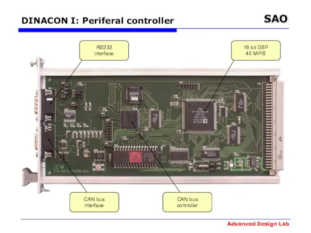
DINACON I: Periferal controller
16 bit DSP
40 MIPS
CAN bus
controller
CAN bus
interface
RS232
interface
DINACON I: Periferal controller
16 bit DSP
40 MIPS
CAN bus
controller
CAN bus
interface
RS232
interface

DINASYS: Control Sofware
DINASYS: Control Sofware
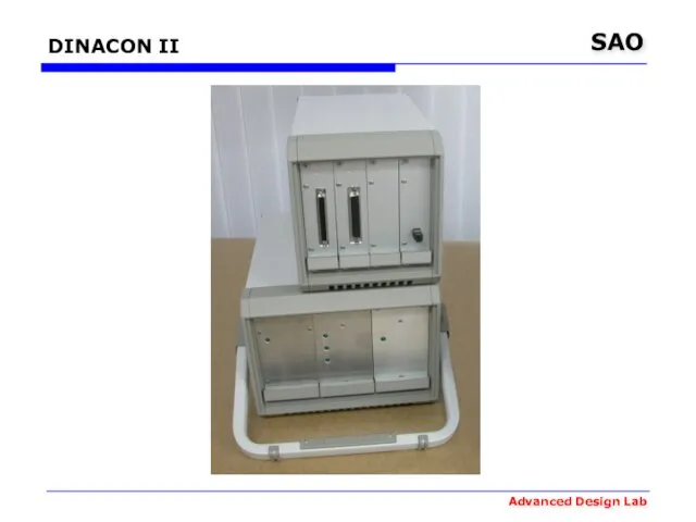
DINACON II
DINACON II
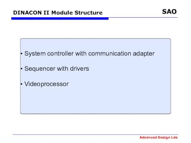
DINACON II Module Structure
System controller with communication adapter
Sequencer with
DINACON II Module Structure
System controller with communication adapter
Sequencer with
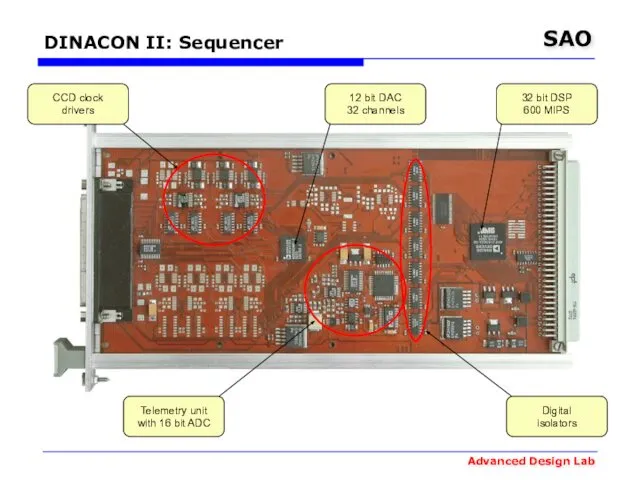
DINACON II: Sequencer
CCD clock
drivers
Telemetry unit
with 16 bit ADC
12 bit DAC
32 channels
32
DINACON II: Sequencer
CCD clock
drivers
Telemetry unit
with 16 bit ADC
12 bit DAC
32 channels
32
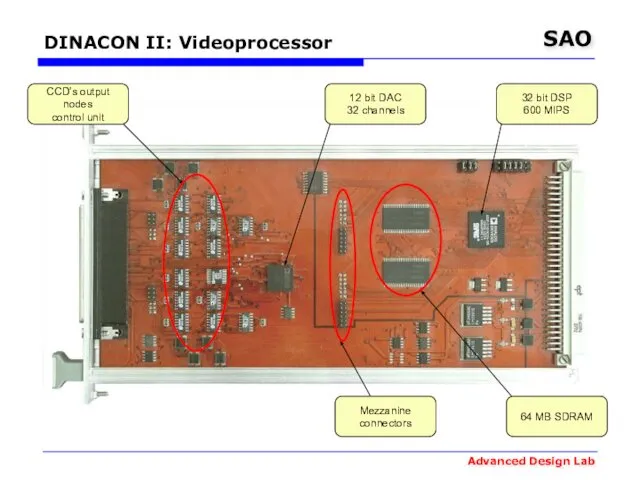
DINACON II: Videoprocessor
CCD’s output nodes
control unit
12 bit DAC
32 channels
32 bit DSP
600
DINACON II: Videoprocessor
CCD’s output nodes
control unit
12 bit DAC
32 channels
32 bit DSP
600
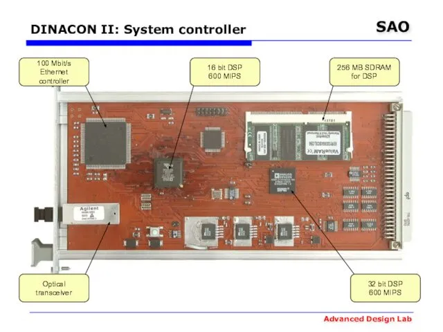
DINACON II: System controller
100 Mbit/s
Ethernet
controller
16 bit DSP
600 MIPS
256 MB SDRAM
for
DINACON II: System controller
100 Mbit/s
Ethernet
controller
16 bit DSP
600 MIPS
256 MB SDRAM
for
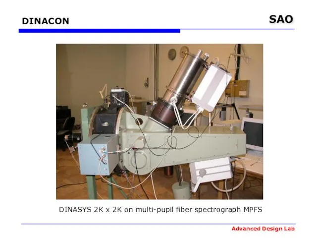
DINACON
DINASYS 2K x 2K on multi-pupil fiber spectrograph MPFS
DINACON
DINASYS 2K x 2K on multi-pupil fiber spectrograph MPFS
DINACON
DINASYS 2K x 2k on multi-mode focal reducer SCORPIO
DINACON
DINASYS 2K x 2k on multi-mode focal reducer SCORPIO

DINACON III
Camera 2K x 4.5k and controller (without power supply)
DINACON III
Camera 2K x 4.5k and controller (without power supply)
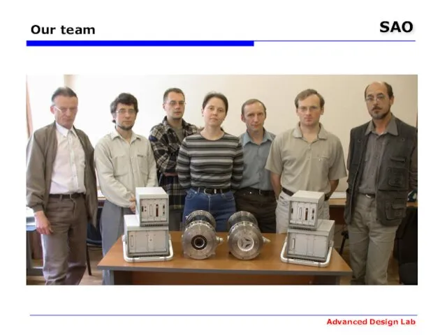
Our team
Our team
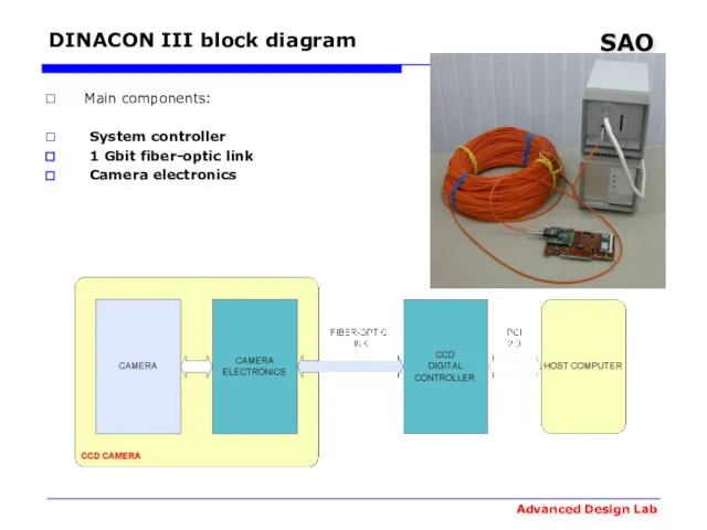
DINACON III block diagram
Main components:
System controller
1 Gbit fiber-optic
DINACON III block diagram
Main components:
System controller
1 Gbit fiber-optic
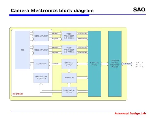
Camera Electronics block diagram
Camera Electronics block diagram
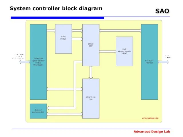
System controller block diagram
System controller block diagram
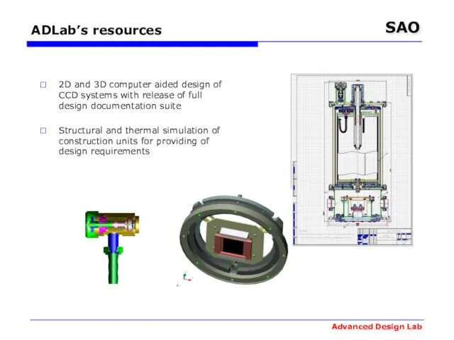
ADLab’s resources
2D and 3D computer aided design of CCD systems with
ADLab’s resources
2D and 3D computer aided design of CCD systems with
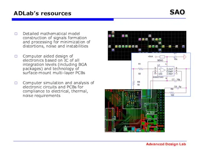
ADLab’s resources
Detailed mathematical model construction of signals formation and processing for
ADLab’s resources
Detailed mathematical model construction of signals formation and processing for
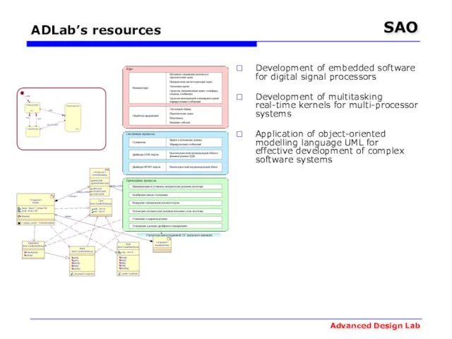
ADLab’s resources
Development of embedded software for digital signal processors
Development of multitasking
ADLab’s resources
Development of embedded software for digital signal processors
Development of multitasking
ADLab’s resources
Production of multi-layer PCB prototypes
Surface mounting of electronic components on
ADLab’s resources
Production of multi-layer PCB prototypes
Surface mounting of electronic components on
 Чтобы помнили
 Соли
Соли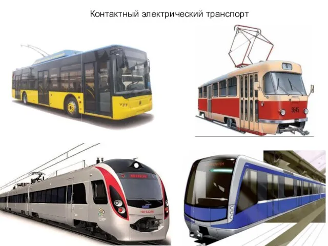 Контактный электрический транспорт
 Родительское собрание
 Пластилиновая азбука. Хамелеон
 Проект Нанополимер
 Генеральный план городского округа Тольятти на расчётный срок до 2025 года
 BUKTREJLER
 Проектирование объектов архитектурной среды
 Создаем элементы образа будущего: что мы хотим изменить своим проектом
 Шрифты и ГОСТ
 20151216_zashchita_naseleniya_ot_avariyno_himicheski_opasnyh_veshchestv
 Общая характеристика авиационных приборов (АП) и систем как объектов моделирования
 Фото-галерея
 Об организации профилактики суицидального поведения несовершеннолетних
 Dengi
Dengi Раціональне і ефективне ресурсів
 Рациональная организация рабочего места для резьбы по дереву. Плосковыемочная резьба
 Основы религиозных культур и светской этики (ОРКСЭ)
 20111112_prezentaciya_raevskie
 SpotHunters
 Виды сварки, пайка и напыление
 Основы проектирования
 Ветка сирени
 Kosmicheskoe_v_moey_Ezhve - копия
 Presentation 1
 Ур. 25 Поиск документа
 Урбанизация. Линейные объекты