- HROU 4000

Содержание
- 2. Notes Slides 3-14 are to provide context – this is a fiber fed assembly that outputs
- 3. 1. HROU-4000
- 4. 2. HROU-4000 Appearance 460 625 225 240 725 2-Φ13.0*39.0 (500) 800 1200 690 350 2-R12.5 2-Φ13.0*23.0
- 5. 3. HROU-4000 Interface ports
- 6. 4.1 HROU-4000 Internal structure HROU_4000_DTU HRDU_345 HROPTIC_4000 CU_CBand-345 INTERFACE_B’d Ass’y HROU_4000_PSU_AC HROU_4000_PSU_DC HRDU_Cband HRDU_345_M HRDU_Cband_M CU_CBand-345
- 7. 4.2 HROU-4000 Internal structure (RDU High) HROU_4000_DTU HROPTIC_4000 CU_CBand-345 INTERFACE_B’d Ass’y HROU_4000_PSU_AC HROU_4000_PSU_DC HRDU_Cband HRDU_Cband_M CU_CBand-345
- 8. 5.1. DTU
- 9. 5.2. RDU
- 10. 5.3. PSU-AC
- 11. 5.4. PSU-DC
- 12. 5.5. OPTIC
- 13. 5.6. CU
- 14. 5.7. INTERFACE_UNIT
- 15. Door closed photo The lighting is bad here and makes it look a little yellow. I
- 16. Photo – door open The yellow cable is a fiber optic jumper – you don’t need
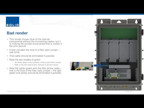
- 17. Bad render This render shows most of the internal components without the connecting cables, but it
- 19. Скачать презентацию
Notes
Slides 3-14 are to provide context – this is a fiber
Notes
Slides 3-14 are to provide context – this is a fiber
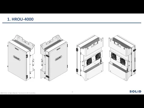
1. HROU-4000
1. HROU-4000
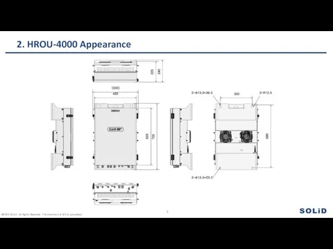
2. HROU-4000 Appearance
460
625
225
240
725
2-Φ13.0*39.0
(500)
800
1200
690
350
2-R12.5
2-Φ13.0*23.0
2. HROU-4000 Appearance
460
625
225
240
725
2-Φ13.0*39.0
(500)
800
1200
690
350
2-R12.5
2-Φ13.0*23.0
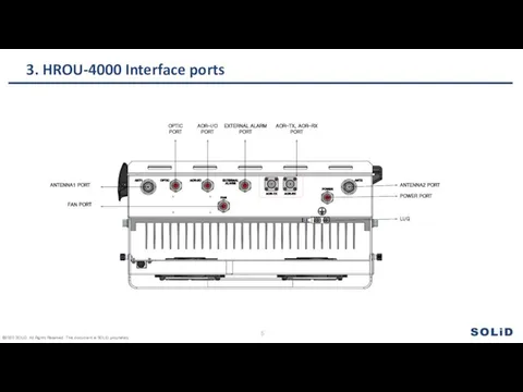
3. HROU-4000 Interface ports
3. HROU-4000 Interface ports
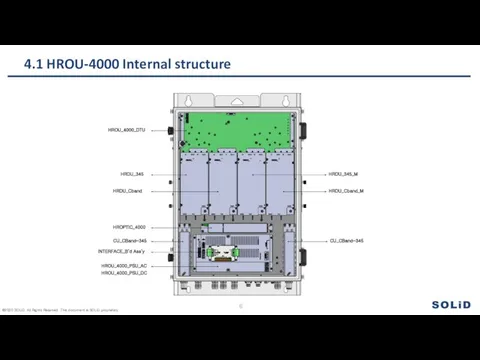
4.1 HROU-4000 Internal structure
HROU_4000_DTU
HRDU_345
HROPTIC_4000
CU_CBand-345
INTERFACE_B’d Ass’y
HROU_4000_PSU_AC
HROU_4000_PSU_DC
HRDU_Cband
HRDU_345_M
HRDU_Cband_M
CU_CBand-345
4.1 HROU-4000 Internal structure
HROU_4000_DTU
HRDU_345
HROPTIC_4000
CU_CBand-345
INTERFACE_B’d Ass’y
HROU_4000_PSU_AC
HROU_4000_PSU_DC
HRDU_Cband
HRDU_345_M
HRDU_Cband_M
CU_CBand-345
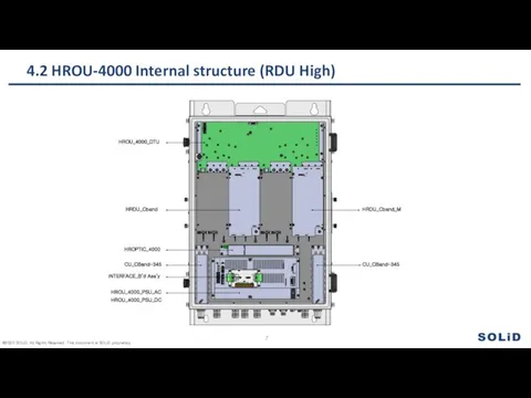
4.2 HROU-4000 Internal structure (RDU High)
HROU_4000_DTU
HROPTIC_4000
CU_CBand-345
INTERFACE_B’d Ass’y
HROU_4000_PSU_AC
HROU_4000_PSU_DC
HRDU_Cband
HRDU_Cband_M
CU_CBand-345
4.2 HROU-4000 Internal structure (RDU High)
HROU_4000_DTU
HROPTIC_4000
CU_CBand-345
INTERFACE_B’d Ass’y
HROU_4000_PSU_AC
HROU_4000_PSU_DC
HRDU_Cband
HRDU_Cband_M
CU_CBand-345
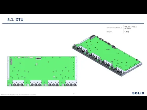
5.1. DTU
5.1. DTU
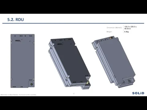
5.2. RDU
5.2. RDU
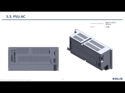
5.3. PSU-AC
5.3. PSU-AC
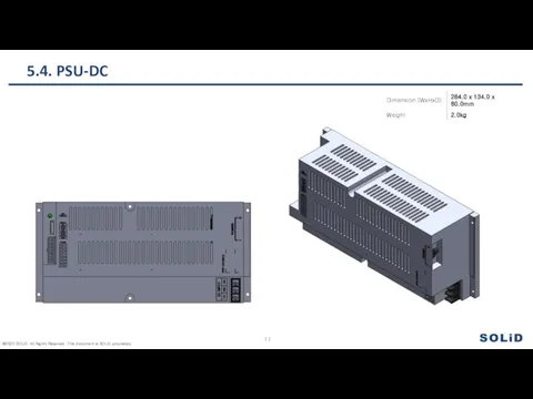
5.4. PSU-DC
5.4. PSU-DC
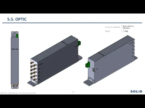
5.5. OPTIC
5.5. OPTIC
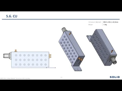
5.6. CU
5.6. CU
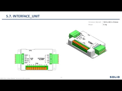
5.7. INTERFACE_UNIT
5.7. INTERFACE_UNIT
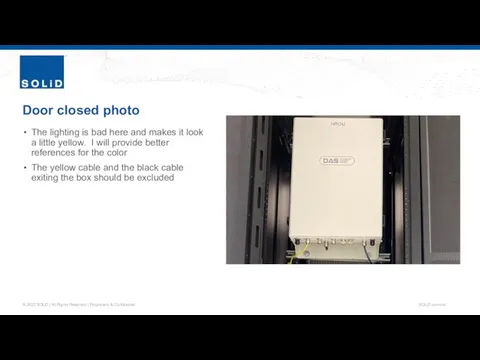
Door closed photo
The lighting is bad here and makes it look
Door closed photo
The lighting is bad here and makes it look
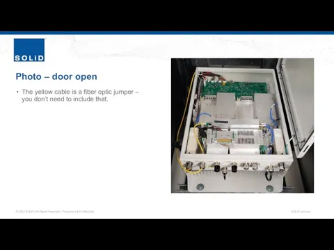
Photo – door open
The yellow cable is a fiber optic jumper
Photo – door open
The yellow cable is a fiber optic jumper
Bad render
This render shows most of the internal components without the
Bad render
This render shows most of the internal components without the
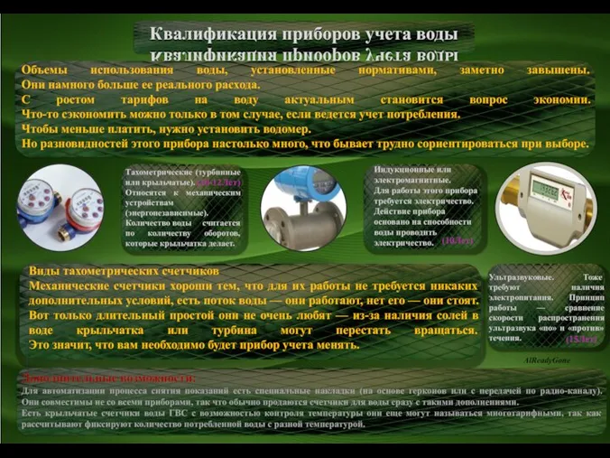 Квалификация учета приборов воды
 презентация
 Благодарение Богу, даровавшему нам победу Господом нашим Иисусом Христом!
 Что такое микроскоп?
 Технология переработки зерна проса в крупу
 Осень. Как мы можем узнать, что уже пришла осень?
 Layout Upwork
 03.20. 5кл. трудовое обучение
 олол
олол 20180824_interaktivnyy_trenazher_po_teme_zvukobukvennyy_analiz
 Uzbek and english poetry
 Устный журнал
 Улучшение эффективных показателей автомобилей в АО Гордормостстрой при эксплуатации в условиях г. Киров
 Modlitwy dziecka
 ppt04
ppt04 20130206_istoriya_pesni_grnada_moya_-_kopiya
 Защищенная автоматизированная система
 Возрастные изменения кожи (опросник)
 Виды новостных сообщений
 Разработка системы управления осветительной установки
 Животноводство
 Растим читателя
 20151115_psihologicheskaya_reabilitatsiya2
 Библия. Тимофея 3,13 - 4,5
 Оптичні засоби корекції
 Машины постоянного тока. Назначение, области применения и устройство машин постоянного тока
 Виды речевых ошибок и их исправление
 Религия во Франции