- Introductions to positioning access points

Содержание
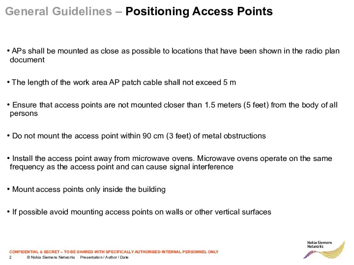
- 2. General Guidelines – Positioning Access Points APs shall be mounted as close as possible to locations
- 3. General Guidelines – Positioning Access Points APs shall be mounted below a ceiling Visual contact between
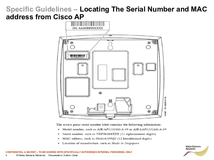
- 4. Specific Guidelines – Locating The Serial Number and MAC address from Cisco AP
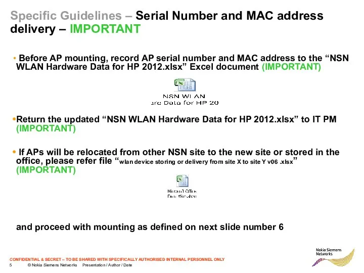
- 5. Specific Guidelines – Serial Number and MAC address delivery – IMPORTANT Before AP mounting, record AP
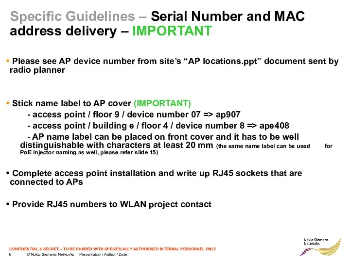
- 6. Specific Guidelines – Serial Number and MAC address delivery – IMPORTANT Please see AP device number
- 7. Specific Guidelines – Cisco 1140 Series AP Layout and Connectors
- 8. Specific Guidelines – Cisco 1140 Series AP Mounting Bracket details
- 9. Specific Guidelines – Cisco 1130 Series AP Layout and Connectors
- 10. Specific Guidelines – Cisco 1130 Series AP Mounting Bracket details
- 11. Specific Guidelines – Mounting the AP on a Horizontal Surface Horizontal mounting below a suspend ceiling
- 12. Specific Guidelines – Poor AP Placement Poor placement, AP placed near physical obstruction (In the example
- 13. Specific Guidelines – Poor AP Placement Poor placement, APs placed near to each other
- 14. General Guidelines – Positioning Access Points Please see more details about Cisco 1140 AP mounting from
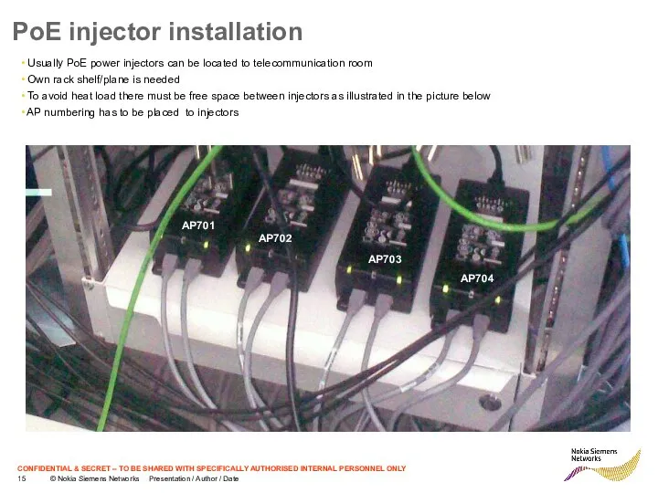
- 15. PoE injector installation Usually PoE power injectors can be located to telecommunication room Own rack shelf/plane
- 17. Скачать презентацию
General Guidelines – Positioning Access Points
APs shall be mounted as
General Guidelines – Positioning Access Points
APs shall be mounted as
General Guidelines – Positioning Access Points
APs shall be mounted below
General Guidelines – Positioning Access Points
APs shall be mounted below
Specific Guidelines – Locating The Serial Number and MAC address from
Specific Guidelines – Locating The Serial Number and MAC address from
Specific Guidelines – Serial Number and MAC address delivery – IMPORTANT
Specific Guidelines – Serial Number and MAC address delivery – IMPORTANT
Specific Guidelines – Serial Number and MAC address delivery – IMPORTANT
Specific Guidelines – Serial Number and MAC address delivery – IMPORTANT
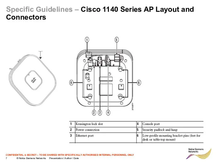
Specific Guidelines – Cisco 1140 Series AP Layout and Connectors
Specific Guidelines – Cisco 1140 Series AP Layout and Connectors
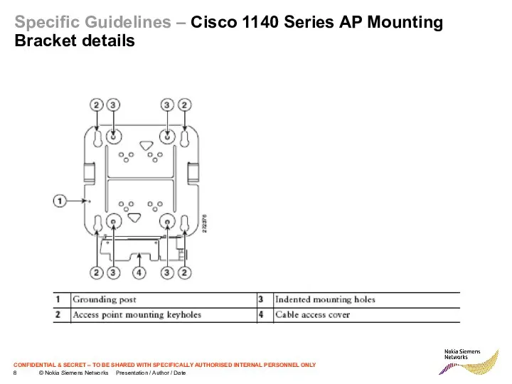
Specific Guidelines – Cisco 1140 Series AP Mounting Bracket details
Specific Guidelines – Cisco 1140 Series AP Mounting Bracket details
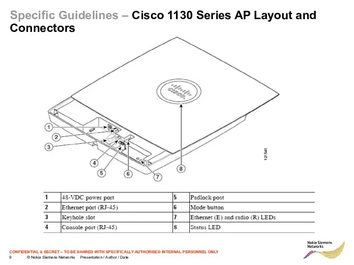
Specific Guidelines – Cisco 1130 Series AP Layout and Connectors
Specific Guidelines – Cisco 1130 Series AP Layout and Connectors
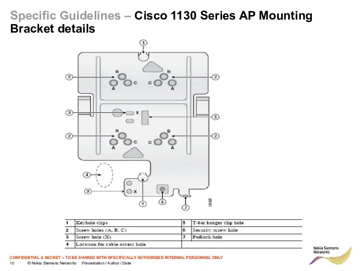
Specific Guidelines – Cisco 1130 Series AP Mounting Bracket details
Specific Guidelines – Cisco 1130 Series AP Mounting Bracket details
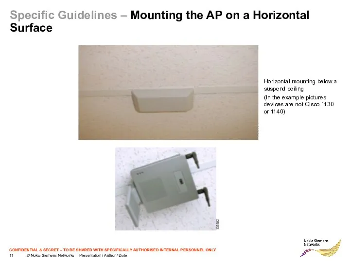
Specific Guidelines – Mounting the AP on a Horizontal Surface
Horizontal mounting
Specific Guidelines – Mounting the AP on a Horizontal Surface
Horizontal mounting
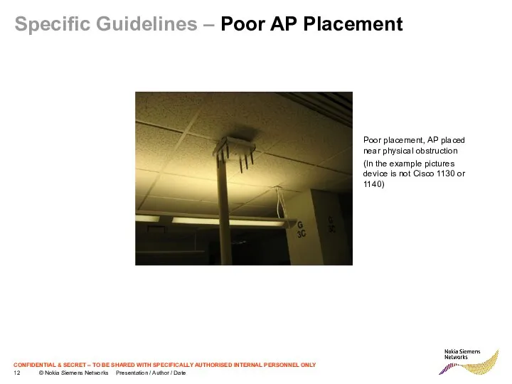
Specific Guidelines – Poor AP Placement
Poor placement, AP placed near
Specific Guidelines – Poor AP Placement
Poor placement, AP placed near
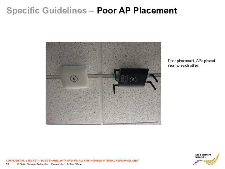
Specific Guidelines – Poor AP Placement
Poor placement, APs placed near to
Specific Guidelines – Poor AP Placement
Poor placement, APs placed near to
General Guidelines – Positioning Access Points
Please see more details about
General Guidelines – Positioning Access Points
Please see more details about
PoE injector installation
Usually PoE power injectors can be located to
PoE injector installation
Usually PoE power injectors can be located to
 Схемотехника телевизионных устройств и устройств отображения информации. (Лекция 7)
 Электроника и схемотехника. Лекция №6. Усилители. Режимы (классы) усилителей. Многокаскадные схемы. Виды межкаскадной связи
 Алюминиевая бронза
 Рефлексия
 Игра в MS Power Point
 20141123_novodvinskaya_krepost
 Самопрезентация_новичка
 Жылу тасымалдағыштың түрлері
 Inżynieria materiałowa i konstrukcja urządzeń
 Образовательный проект Дети учат детей
 Новый угольный терминал. TOSEI
 Инженерная подготовка. Подъездная автодорога
 Рабочая программа образовательная область художественно-эстетическое развитие
 Обзор методической литературы
 Мир на экране здесь и сейчас. Информационная и художественная природа телевизионного изображения
 Схемотехника цифровых устройств. Последовательные схемы
 Оборудование для проведения деловых мероприятий
 Страсні розважання
 Маска. Технологическая последовательность
 Декоративные штукатурки. Известково-песчаные штукатурки
 Инженерные изыскания в строительстве
 ПРОФИЛАКТИКА природоохрана
 Летопись в кадре
 Псалом 18. Вечнозаветная псалтирь
 Понятие плитки и ее применение
 Догадова Галина
 Работаем над сочинением о роли частиц
 Анкетирование