- Simulation of wing-body junction flows with hybrid RANS/LES methods

Содержание
- 2. Introduction Junction flow occurs when a boundary layer encounters an obstruction At realistic large Reynolds number,
- 3. Viewed objects Rood wing-body junction (3:2 elliptical nose and a NACA 0020 tail model) – have
- 4. Numerical methods. Flow equations The computations here are all based on a compressible solver using a
- 5. Numerical methods. Energy and dissipation equations Using the LU-SGS method The production terms are treated explicitly,
- 6. Results. Rood Boundary conditions: at x/T = -18.24: inlet (from experiment) at x/T = 16: outflow
- 7. Difference between SST and WD+ Comparisons on U and k with the WD+ and SST
- 8. Difference on grid Comparisons on U/Uref and k/U2ref based on two grids
- 9. Flowfields on the symmetric plane Comparison of velocity vectors on the symmetric plane
- 10. Flow structures at three streamwise positions Transverse velocity at different streamwise positions (maximum thickness, middle and
- 11. Flow structures at three streamwise positions Flow patterns around the wing-body junction (a) shear stress lines
- 12. Flow structures at three streamwise positions Comparisons of turbulent kinetic energy and cross-streamwise normal stress near
- 13. Flowfields in the wake Comparisons of turbulent kinetic energy and the vertical flow vectors in the
- 14. Results. TN D-712 junction Grids around TN D-712 Wing-fuselage junction.
- 15. Mach number - 0.9 Reynolds number is 7.5 · 106 (based on halfspan) Angle of attack
- 16. Pressure coefficients Comparisons of pressure coefficients of different turbulence methods near the junction
- 17. Vortex over the wing Comparison on vortex over the wing with RANS, DES and DDES methods.
- 18. The instantaneous DDES vorticities over the wing at different AoAs (Left: 12.5; Right: 26.2)
- 19. Flow patterns of DDES Transverse flow structure at different streamwise positions by DDES. 2x/B = 1.667,
- 21. Скачать презентацию
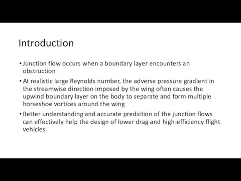
Introduction
Junction flow occurs when a boundary layer encounters an obstruction
At realistic
Introduction
Junction flow occurs when a boundary layer encounters an obstruction
At realistic
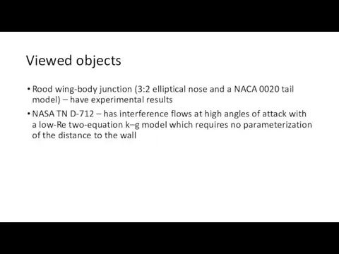
Viewed objects
Rood wing-body junction (3:2 elliptical nose and a NACA 0020
Viewed objects
Rood wing-body junction (3:2 elliptical nose and a NACA 0020

Numerical methods. Flow equations
The computations here are all based on a
Numerical methods. Flow equations
The computations here are all based on a

Numerical methods. Energy and dissipation equations
Using the LU-SGS method
The production terms
Numerical methods. Energy and dissipation equations
Using the LU-SGS method
The production terms
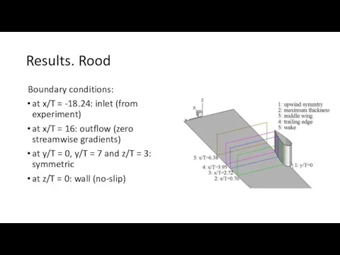
Results. Rood
Boundary conditions:
at x/T = -18.24: inlet (from experiment)
at x/T
Results. Rood
Boundary conditions:
at x/T = -18.24: inlet (from experiment)
at x/T

Difference between SST and WD+
Comparisons on U and k with the
Difference between SST and WD+
Comparisons on U and k with the

Difference on grid
Comparisons on U/Uref and k/U2ref based on two grids
Difference on grid
Comparisons on U/Uref and k/U2ref based on two grids

Flowfields on the symmetric plane
Comparison of velocity vectors on the symmetric
Flowfields on the symmetric plane
Comparison of velocity vectors on the symmetric

Flow structures at three streamwise positions
Transverse velocity at different streamwise positions
Flow structures at three streamwise positions
Transverse velocity at different streamwise positions
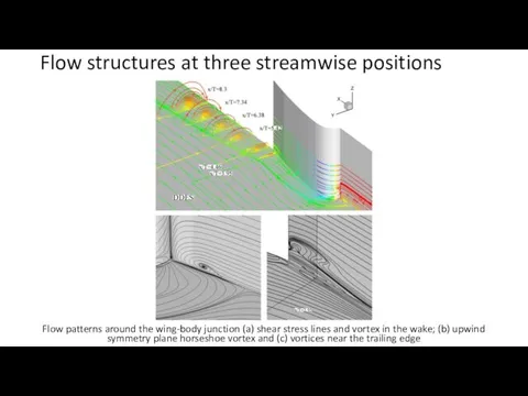
Flow structures at three streamwise positions
Flow patterns around the wing-body junction
Flow structures at three streamwise positions
Flow patterns around the wing-body junction

Flow structures at three streamwise positions
Comparisons of turbulent kinetic energy and
Flow structures at three streamwise positions
Comparisons of turbulent kinetic energy and
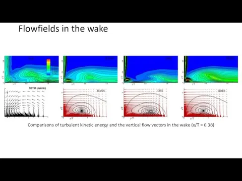
Flowfields in the wake
Comparisons of turbulent kinetic energy and the vertical
Flowfields in the wake
Comparisons of turbulent kinetic energy and the vertical

Results. TN D-712 junction
Grids around TN D-712 Wing-fuselage junction.
Results. TN D-712 junction
Grids around TN D-712 Wing-fuselage junction.
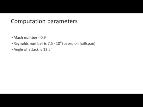
Mach number - 0.9
Reynolds number is 7.5 · 106 (based on
Mach number - 0.9
Reynolds number is 7.5 · 106 (based on

Pressure coefficients
Comparisons of pressure coefficients of different turbulence methods near the
Pressure coefficients
Comparisons of pressure coefficients of different turbulence methods near the
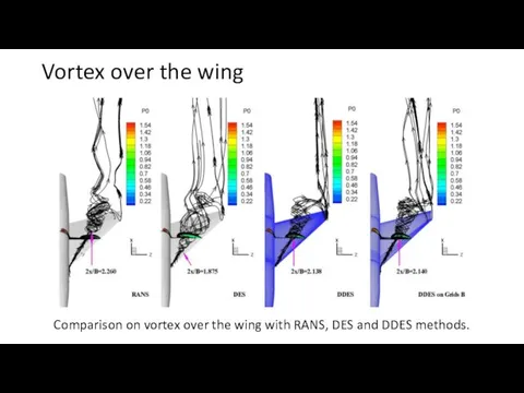
Vortex over the wing
Comparison on vortex over the wing with RANS,
Vortex over the wing
Comparison on vortex over the wing with RANS,

The instantaneous DDES vorticities over the wing at different AoAs (Left:
The instantaneous DDES vorticities over the wing at different AoAs (Left:

Flow patterns of DDES
Transverse flow structure at different streamwise positions by
Flow patterns of DDES
Transverse flow structure at different streamwise positions by
 Монтаж, техническая эксплуатация и обслуживание вакуумных выключателей
 Определение, этапы и компоненты программы совершенствования коммуникаций в организации
 Библейские сказания
 Основа для проектирования: лицензия, горный отвод, учет и классификация запасов
 Ни минуты не теряя, мы здоровье укрепляем
 Боря. Робот-разведчик
 20131223_prez.urok23._oktyabr
 20141211_drevniy_rim
 Od osoby, która cię kocha
 Подготовка деревянных поверхностей под окраску масляными составами
 Правила технической эксплуатации железных дорог Российской Федерации
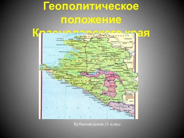 20180405_geopoliticheskoe_polozhenie_krasnodarskogo_kraya
 Мясные копчености
 tUaHoJlgewBqcC2FUjaDsg
 Теплообменные аппараты
 Педагогические коммуникации
 чему и как учились при Петре
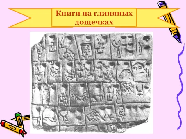 Книги на глиняных дощечках
 结构助词. Структурная частица
 Евангелие от Матфея 25,1-13
 Интересные факты о литературе
 Проект дуговой сталеплавильной печи G=12 т
 Точность механической обработки и погрешности изготовления деталей
 Схемотехника аналоговых устройств
 Воспитание силовых способностей в становой тяге у юношей на примере силового троеборья
 Газовая промышленность
 вопросы диф зачет 238
 урок 76.9