- Visual Output

Содержание
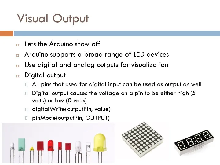
- 2. Visual Output Lets the Arduino show off Arduino supports a broad range of LED devices Use
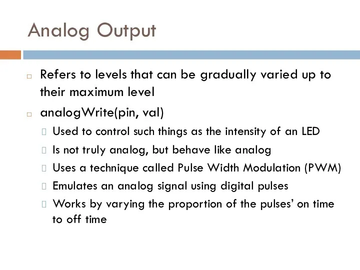
- 3. Analog Output Refers to levels that can be gradually varied up to their maximum level analogWrite(pin,
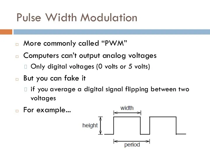
- 4. Pulse Width Modulation More commonly called “PWM” Computers can’t output analog voltages Only digital voltages (0
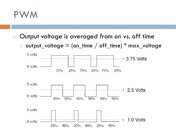
- 5. PWM Output voltage is averaged from on vs. off time output_voltage = (on_time / off_time) *
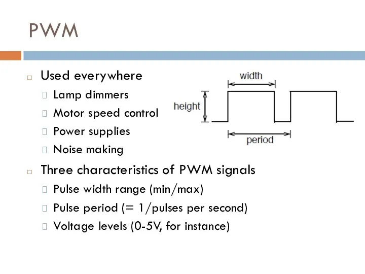
- 6. PWM Used everywhere Lamp dimmers Motor speed control Power supplies Noise making Three characteristics of PWM
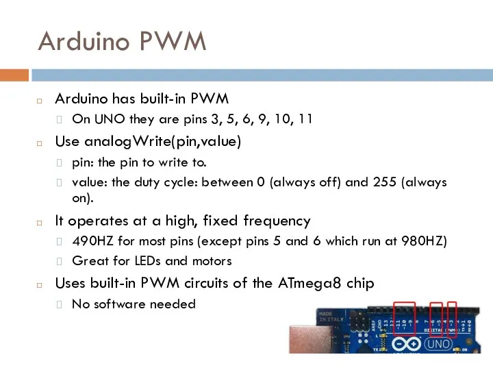
- 7. Arduino PWM Arduino has built-in PWM On UNO they are pins 3, 5, 6, 9, 10,
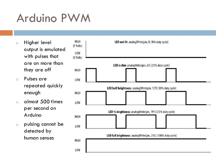
- 8. Arduino PWM Higher level output is emulated with pulses that are on more than they are
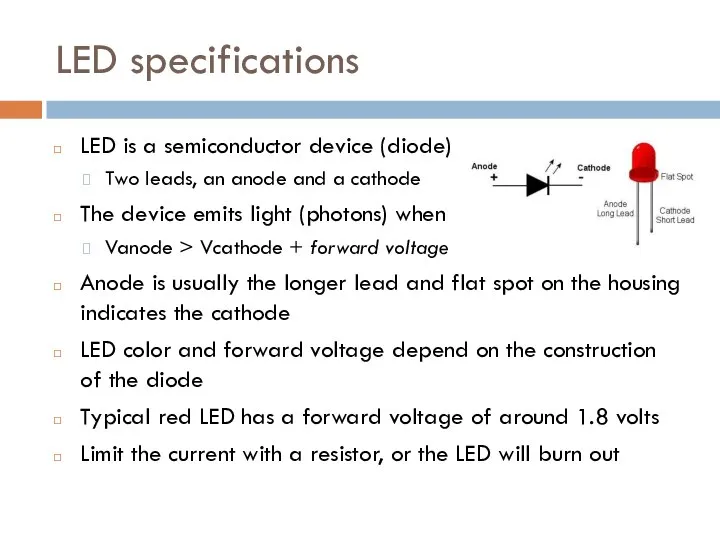
- 9. LED specifications LED is a semiconductor device (diode) Two leads, an anode and a cathode The
- 10. Consult an LED data sheet Arduino pins can supply up to 40 mA of current This
- 11. Adjusting the Brightness of an LED Connect each LED to an analog (PWM) output const int
- 12. Driving High-Power LEDs Arduino can handle current up to 40 mA per pin Use a transistor
- 13. How to Exceed 40 mA per Pin Connect multiple pins in parallel to increase current beyond
- 14. Adjusting the Color of an LED RGB LEDs have red, green, and blue elements in a
- 15. Adjusting the Color of an LED const int redPin = 3; // choose the pin for
- 16. Driving a 7-Segment LED Display Contains 8 LEDs (including Decimal Point indicator) Common Anode & Common
- 17. Driving a 7-Segment LED Display const byte numeral[10][8] = { {1,1,1,1,1,1,0,0}, // 0 {0,1,1,0,0,0,0,0}, // 1
- 18. Multidigit, 7-Segment: Multiplexing Corresponding segments from each digit are connected together
- 19. Multidigit, 7-Segment: Multiplexing const byte numeral[10][8] = { {1,1,1,1,1,1,0,0}, // 0 {0,1,1,0,0,0,0,0}, // 1 {1,1,0,1,1,0,1,0}, //
- 20. Multiplexing To control many LEDs use a technique called multiplexing Multiplexing is switching groups of LEDs
- 21. Controlling an LED Matrix 8X8 LED matrix contains 64 LEDs Anodes connected in rows and cathodes
- 22. Lighting Each Pixel of LED Matrix const int columnPins[] = { 2, 3, 4, 5, 6,
- 23. Displaying Images on an LED Matrix byte bigHeart[] = { B01100110, B11111111, B11111111, B11111111, B01111110, B00111100,
- 24. Controlling LEDs: Charlieplexing Charlieplexing - increases the number of LEDs that can be driven by a
- 26. Скачать презентацию
Visual Output
Lets the Arduino show off
Arduino supports a broad range of
Visual Output
Lets the Arduino show off
Arduino supports a broad range of
Analog Output
Refers to levels that can be gradually varied up to
Analog Output
Refers to levels that can be gradually varied up to
Pulse Width Modulation
More commonly called “PWM”
Computers can’t output analog voltages
Only digital
Pulse Width Modulation
More commonly called “PWM”
Computers can’t output analog voltages
Only digital
PWM
Output voltage is averaged from on vs. off time
output_voltage = (on_time
PWM
Output voltage is averaged from on vs. off time
output_voltage = (on_time
PWM
Used everywhere
Lamp dimmers
Motor speed control
Power supplies
Noise making
Three characteristics of PWM signals
Pulse
PWM
Used everywhere
Lamp dimmers
Motor speed control
Power supplies
Noise making
Three characteristics of PWM signals
Pulse
Arduino PWM
Arduino has built-in PWM
On UNO they are pins 3, 5,
Arduino PWM
Arduino has built-in PWM
On UNO they are pins 3, 5,
Arduino PWM
Higher level output is emulated with pulses that are on
Arduino PWM
Higher level output is emulated with pulses that are on
LED specifications
LED is a semiconductor device (diode)
Two leads, an anode and
LED specifications
LED is a semiconductor device (diode)
Two leads, an anode and
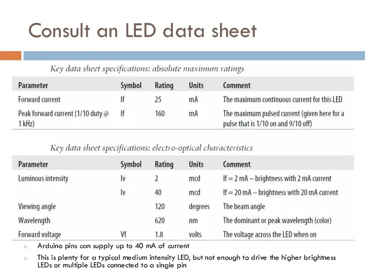
Consult an LED data sheet
Arduino pins can supply up to 40
Consult an LED data sheet
Arduino pins can supply up to 40
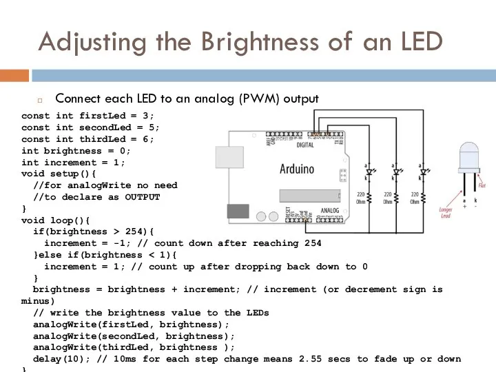
Adjusting the Brightness of an LED
Connect each LED to an analog
Adjusting the Brightness of an LED
Connect each LED to an analog
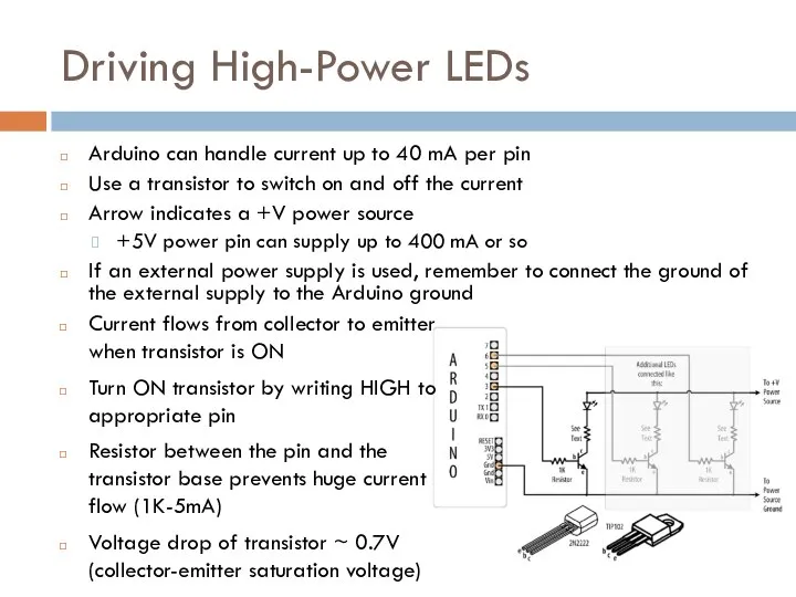
Driving High-Power LEDs
Arduino can handle current up to 40 mA per
Driving High-Power LEDs
Arduino can handle current up to 40 mA per
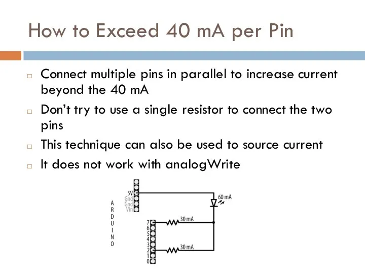
How to Exceed 40 mA per Pin
Connect multiple pins in parallel
How to Exceed 40 mA per Pin
Connect multiple pins in parallel

Adjusting the Color of an LED
RGB LEDs have red, green, and
Adjusting the Color of an LED
RGB LEDs have red, green, and
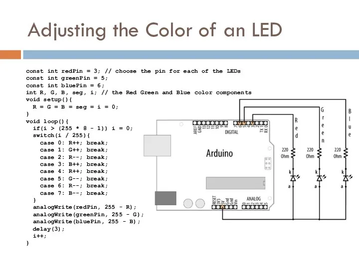
Adjusting the Color of an LED
const int redPin = 3; //
Adjusting the Color of an LED
const int redPin = 3; //
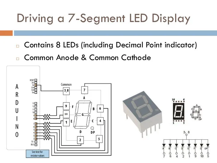
Driving a 7-Segment LED Display
Contains 8 LEDs (including Decimal Point indicator)
Common
Driving a 7-Segment LED Display
Contains 8 LEDs (including Decimal Point indicator)
Common
![Driving a 7-Segment LED Display const byte numeral[10][8] = { {1,1,1,1,1,1,0,0},](/_ipx/f_webp&q_80&fit_contain&s_1440x1080/imagesDir/jpg/622026/slide-16.jpg)
Driving a 7-Segment LED Display
const byte numeral[10][8] = {
{1,1,1,1,1,1,0,0}, //
Driving a 7-Segment LED Display
const byte numeral[10][8] = {
{1,1,1,1,1,1,0,0}, //
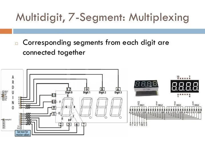
Multidigit, 7-Segment: Multiplexing
Corresponding segments from each digit are connected together
Multidigit, 7-Segment: Multiplexing
Corresponding segments from each digit are connected together
![Multidigit, 7-Segment: Multiplexing const byte numeral[10][8] = { {1,1,1,1,1,1,0,0}, // 0](/_ipx/f_webp&q_80&fit_contain&s_1440x1080/imagesDir/jpg/622026/slide-18.jpg)
Multidigit, 7-Segment: Multiplexing
const byte numeral[10][8] = {
{1,1,1,1,1,1,0,0}, // 0
{0,1,1,0,0,0,0,0},
Multidigit, 7-Segment: Multiplexing
const byte numeral[10][8] = {
{1,1,1,1,1,1,0,0}, // 0
{0,1,1,0,0,0,0,0},
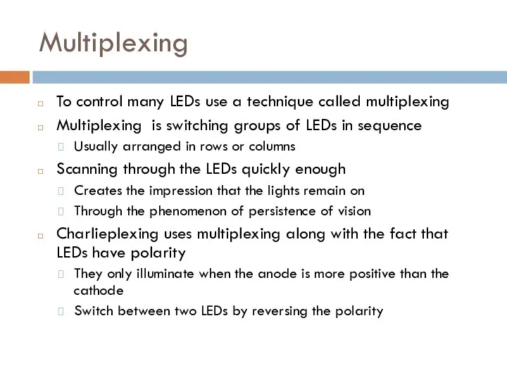
Multiplexing
To control many LEDs use a technique called multiplexing
Multiplexing is switching
Multiplexing
To control many LEDs use a technique called multiplexing
Multiplexing is switching
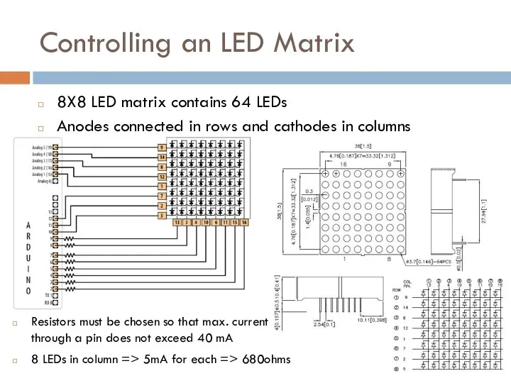
Controlling an LED Matrix
8X8 LED matrix contains 64 LEDs
Anodes connected in
Controlling an LED Matrix
8X8 LED matrix contains 64 LEDs
Anodes connected in
![Lighting Each Pixel of LED Matrix const int columnPins[] = {](/_ipx/f_webp&q_80&fit_contain&s_1440x1080/imagesDir/jpg/622026/slide-21.jpg)
Lighting Each Pixel of LED Matrix
const int columnPins[] = { 2,
Lighting Each Pixel of LED Matrix
const int columnPins[] = { 2,
![Displaying Images on an LED Matrix byte bigHeart[] = { B01100110,](/_ipx/f_webp&q_80&fit_contain&s_1440x1080/imagesDir/jpg/622026/slide-22.jpg)
Displaying Images on an LED Matrix
byte bigHeart[] = {
B01100110,
B11111111,
B11111111,
B11111111,
B01111110,
B00111100,
B00011000,
B00000000};
byte smallHeart[] =
Displaying Images on an LED Matrix
byte bigHeart[] = {
B01100110,
B11111111,
B11111111,
B11111111,
B01111110,
B00111100,
B00011000,
B00000000};
byte smallHeart[] =
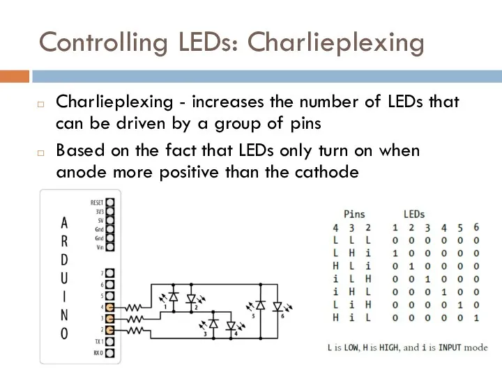
Controlling LEDs: Charlieplexing
Charlieplexing - increases the number of LEDs that can
Controlling LEDs: Charlieplexing
Charlieplexing - increases the number of LEDs that can
 Христинский смысл таинства крещения
 Основные направления деятельности МЗ Арсенал
 HSEの東洋学部
 Почетная грамота
 Устройство и текущее содержание железнодорожного пути. Исправление пути на пучинах
 Перспективы развития оборудования с ЧПУ на основе расширения технологических возможностей
 Кормление дойных коров
 Конденсатно-питательная система
 Мудборд
 Адалдық сағаты
 Образец распоряжения о переводе в уплату в бюджет
 Продвинутые таймеры на STM32F1xx
 Ресурсы, понятие и их классификация
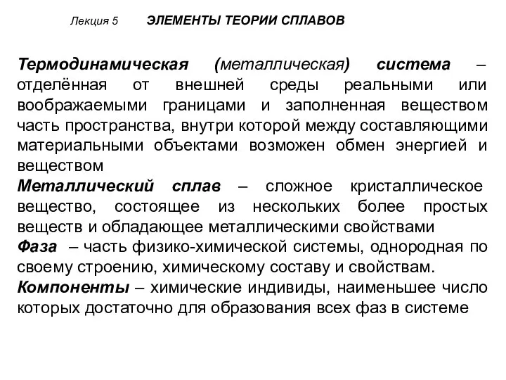 Элементы теории сплавов (Лекция 5)
 Интенсив. Mr.Braun
 Презентация11 класс
 ТЭУ_102_Задание на 270320
 Перевод котла ПК-10 на сжигание газообразного топлива
 САР расхода с комбинированной ветвью
 Как взрослому/учителю развивать эмоциональную саморегуляцию у детей
 Джйотиш (разделы)
 Трудовое право, ЮБ1703
 Пейзажная живопись и графика Японии
 Промежуточная аттестация (первое полугодие, декабрь)
 Биопсия пищевода Павлодар
 Спортзал будущего
 Расчет физических свойств газа при условиях перекачки (занятие 1)
 Моделирование плечевого изделия с использованием ИКТ. Интегрированный урок русский язык + технология