- AMT Technical Training. Automatic Mechanical Transmission

Содержание
- 2. Kindly attention: 1.The course will take you approx 45 minutes 2.Please linsten carefully,and we will have
- 3. Catalog Components Service standard Trouble-shooting and solutions
- 4. System overview
- 5. Following information display on LCD and cluster: Current gears, Current mode(Auto/Manual) Normal/Economical(Shifting pattern under auto Mode)
- 6. System layout 1ECU 2 Electrohydraulic unit 3TCU 4 Cluster 5Econ/Norm button 6brake switch 7Shift lever 8Accelerator
- 7. System introduction On the basis of the original manual transmission gearbox and clutch to add auxiliary
- 8. Shift lever position with three stable and three unstable position, the position signal was transformed by
- 9. Shift to Neutral during running APP sensor released Vehicle speed requirement System introduction
- 10. Shift to Reverse Brake pedal was depressed Vehicle speed Requirement R System introduction
- 11. Possible following situation may cause when the driver try to move shift lever without depressing the
- 12. Knowledge prepration Three types of operation on transmission are replace by Actuator ( Electrohydraulic mechanism )
- 13. Electrohydraulic Mechanism
- 14. ECU Brake switch -----------? Clutch speed --- --- --- ? Clutch fork position--? Gear selected position?
- 15. Input signal TCU APP sensor Brake switch Mode switch(M/A) Econ/Norm button Shift Up/down(+/-) switch Vehicle speed
- 16. Input signal TCU Gear engage position sensor Gear selection sensor Clutch fork position sensor Friction disc
- 17. Output signal TCU Clutch solenoid valve(EV0) Even gears engage solenoid valve(EV2) 1-2 gears selection solenoid valve(EV3)
- 18. System specification
- 19. System will be woke up in two ways: — Open the driver's side door: The system
- 20. Engine start control Start requirement: Once TCU receives the brake (except Neutral gear) and the start
- 21. Vehicle can start to move on 1st & 2nd gear Starting move Driver release brake pedal
- 22. Shift process under Manual Mode Shift process When vehicle is running and the clutch engaged, driver
- 23. Control intervention under Manual Mode In Manual mode, TCU will control the gears automatically avoid overspeed
- 24. Auto mode Shift lever can switch to automatic mode at any time(If condition is met).Once automatic
- 25. When the driver stepped on the accelerator to fully open, TCU will downshift one or two
- 26. Deceleration TCU will automatically downshift during deceleration and the gears above 2nd gear. For example, in
- 27. System security features
- 28. When the vehicle stopped but the engine working and engage gear (such as 1st , 2nd
- 29. Emergency start during brake switch is broken If the TCU detected brake switch is broken, Ignition
- 30. System control theory APP sensor Brake switch Dash panel Door switch Shift lever Vehicle speed TCU
- 31. Components
- 32. Shift components
- 33. Shift gears Shift pin Selection gear 5-R shift fork 3-4 shift fork
- 34. Hydraulic actuator SQR 513 transmission hydraulic actuator location (Bracket of hydraulic actuator must be remove)
- 35. Power Unit Hydraulic power unit provides power to hydraulic. Motor Accumulator Gear pump Low pressure fluid
- 36. Pump 12V DC。 System pressure: >46 bar stop TCU 30 31
- 37. Tank 150 micrometer filter was fitted in exports of tank. Fluid level standard Relief system pressure
- 38. Accumulator Capacity:250 cm3
- 39. Valve body Valve body has follow functions: Control gear engage and detach。 Control gear selection Control
- 40. Valve body Joint Mounting location
- 41. Clutch actuator
- 42. Clutch actuator assembly 1. Release cable 2. Clutch actuator body 3. Clutch cable position sensor 4.
- 43. Data stream in X431 concerning clutch
- 44. Clutch cable position sensor Function: feedback the clutch cable position signal to TCU
- 45. Gear engage and selection solenoid valves
- 46. Gear engage solenoid valves Even gear engage valve(EV2) Odd gear engage valve(EV1)
- 47. Gear selection valves 1-2 gears selection solenoid valve(EV3) 5-R gears selection solenoid valve(EV4)
- 48. Summary of solenoid valves
- 49. Pressure sensor Function :Monitor system pressure
- 50. Pressure sensor What is special meaning that the range from 36-46 bar? TCU + - Pressure
- 51. Maintenance specification ——AMT system self-learn
- 52. System maintenance services Replace or assemble parts must perform the following functions in whole or in
- 53. Service should be taken after parts replacement
- 54. ——Guide of dismount and assemble Maintenance specification
- 55. Pressure Fluid Abnormal pressure fluid add into system will cause a serious situation and miss the
- 56. Before removing the AMT ASSM, selection shaft must be released. Remove the cover Rotate the selection
- 57. Mount guide First of all, after cleaning and coating sealant, should ensure a good seal interfaces
- 58. Remove cover Select shaft must be adjusted to the self-locking pole position, then press it down,
- 59. Fault code
- 60. Fault code
- 61. Trouble-shooting and solutions
- 62. Problem I: The vehicle shivers noticeably upon releasing the accelerator pedal at the first, second or
- 63. Problem II: The transmission failure lamp is lit during movement, and the failure code P0715 (friction
- 64. Problem III: Friction disc revolution sensor failure; the gear is locked at the first/second gear, allowing
- 65. 4. Clutch position sensor failure (in this case, P1810 and P0715 will be indicated at the
- 66. Problem IV: Oil leakage in the oil pot Causes: 1. The vent on the pot cover
- 67. Problem V: There is trip stop or failure of gear engagement in the vehicle, and the
- 68. Problem VI: One of direct gears is always missing in the operation, for example, the transmission
- 69. Problem VII 1. No depression of the accelerator pedal is required in the engagement of the
- 70. Problem VIII: After the transmission is shifted to the first gear and the vehicle is stopped,
- 71. Thank you very much!
- 72. Pratice Check resistence of each solenoid valve。 Remove gear selection/gear engage sensor/ clutch sensor and how
- 74. Скачать презентацию

Kindly attention:
1.The course will take you approx 45 minutes
2.Please linsten carefully,and
Kindly attention:
1.The course will take you approx 45 minutes
2.Please linsten carefully,and

Catalog
Components
Service standard
Trouble-shooting and solutions
Catalog
Components
Service standard
Trouble-shooting and solutions

System overview
System overview

Following information display on LCD and cluster:
Current gears, Current mode(Auto/Manual)
Normal/Economical(Shifting pattern
Following information display on LCD and cluster:
Current gears, Current mode(Auto/Manual)
Normal/Economical(Shifting pattern

System layout
1ECU 2 Electrohydraulic unit 3TCU 4 Cluster
5Econ/Norm button 6brake switch 7Shift lever 8Accelerator
System layout
1ECU 2 Electrohydraulic unit 3TCU 4 Cluster
5Econ/Norm button 6brake switch 7Shift lever 8Accelerator

System introduction
On the basis of the original manual transmission gearbox and
System introduction
On the basis of the original manual transmission gearbox and
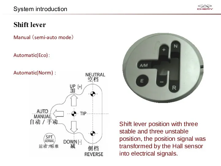
Shift lever position with three stable and three unstable position, the
Shift lever position with three stable and three unstable position, the

Shift to Neutral during running
APP sensor released
Vehicle speed <80KM/H
requirement
System introduction
Shift to Neutral during running
APP sensor released
Vehicle speed <80KM/H
requirement
System introduction

Shift to Reverse
Brake pedal
was depressed
Vehicle speed
<2Km/h
Requirement
R
System introduction
Shift to Reverse
Brake pedal
was depressed
Vehicle speed
<2Km/h
Requirement
R
System introduction
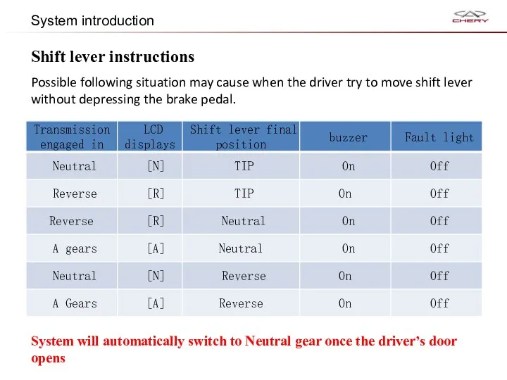
Possible following situation may cause when the driver try to move
Possible following situation may cause when the driver try to move

Knowledge prepration
Three types of operation on transmission are replace by Actuator
Knowledge prepration
Three types of operation on transmission are replace by Actuator

Electrohydraulic Mechanism
Electrohydraulic Mechanism

ECU<-------------?
Brake switch -----------?
Clutch speed --- --- --- ?
Clutch fork position--?
Gear
ECU<-------------?
Brake switch -----------?
Clutch speed --- --- --- ?
Clutch fork position--?
Gear

Input signal
TCU
APP sensor
Brake switch
Mode switch(M/A)
Econ/Norm button
Shift Up/down(+/-) switch
Vehicle speed sensor
Engine
Input signal
TCU
APP sensor
Brake switch
Mode switch(M/A)
Econ/Norm button
Shift Up/down(+/-) switch
Vehicle speed sensor
Engine
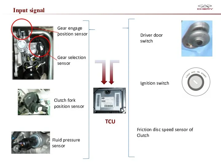
Input signal
TCU
Gear engage position sensor
Gear selection sensor
Clutch fork position sensor
Friction disc
Input signal
TCU
Gear engage position sensor
Gear selection sensor
Clutch fork position sensor
Friction disc

Output signal
TCU
Clutch solenoid valve(EV0)
Even gears engage solenoid valve(EV2)
1-2 gears selection solenoid
Output signal
TCU
Clutch solenoid valve(EV0)
Even gears engage solenoid valve(EV2)
1-2 gears selection solenoid
System specification
System specification

System will be woke up in two ways:
— Open the driver's
System will be woke up in two ways:
— Open the driver's

Engine start control
Start requirement:
Once TCU receives the brake (except Neutral gear)
Engine start control
Start requirement:
Once TCU receives the brake (except Neutral gear)

Vehicle can start to move on 1st & 2nd gear
Starting move
Driver
Vehicle can start to move on 1st & 2nd gear
Starting move
Driver

Shift process under Manual Mode
Shift process
When vehicle is running and the
Shift process under Manual Mode
Shift process
When vehicle is running and the

Control intervention under Manual Mode
In Manual mode, TCU will control the
Control intervention under Manual Mode
In Manual mode, TCU will control the

Auto mode
Shift lever can switch to automatic mode at any time(If
Auto mode
Shift lever can switch to automatic mode at any time(If
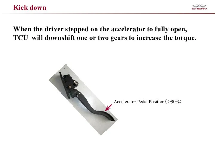
When the driver stepped on the accelerator to fully open, TCU
When the driver stepped on the accelerator to fully open, TCU
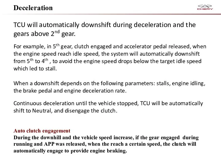
Deceleration
TCU will automatically downshift during deceleration and the gears above 2nd
Deceleration
TCU will automatically downshift during deceleration and the gears above 2nd

System security features
System security features
When the vehicle stopped but the engine working and engage gear
When the vehicle stopped but the engine working and engage gear

Emergency start during brake switch is broken
If the TCU detected brake
Emergency start during brake switch is broken
If the TCU detected brake

System control theory
APP sensor
Brake switch
Dash panel
Door switch
Shift lever
Vehicle speed
TCU
ECU
Engine
Hydraulic system
solenoid valves
Transmission
System control theory
APP sensor
Brake switch
Dash panel
Door switch
Shift lever
Vehicle speed
TCU
ECU
Engine
Hydraulic system
solenoid valves
Transmission

Components
Components

Shift components
Shift components
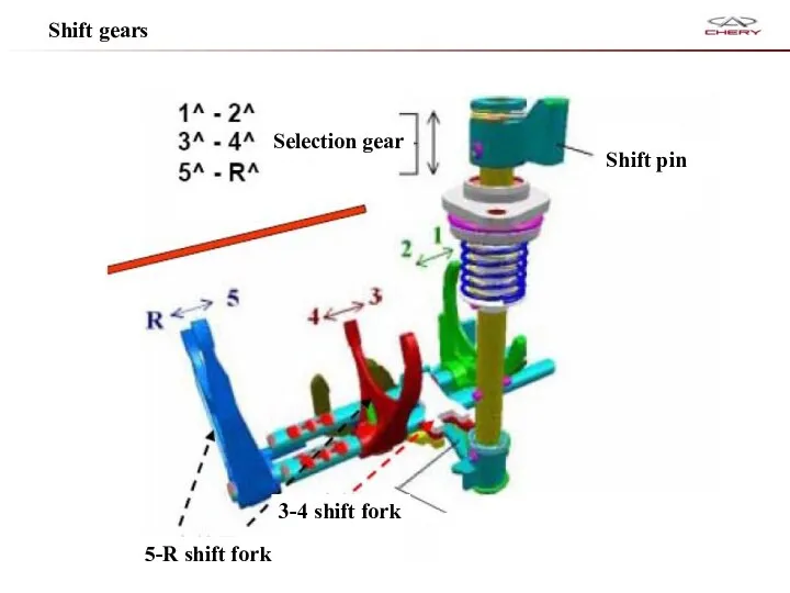
Shift gears
Shift pin
Selection gear
5-R shift fork
3-4 shift fork
Shift gears
Shift pin
Selection gear
5-R shift fork
3-4 shift fork
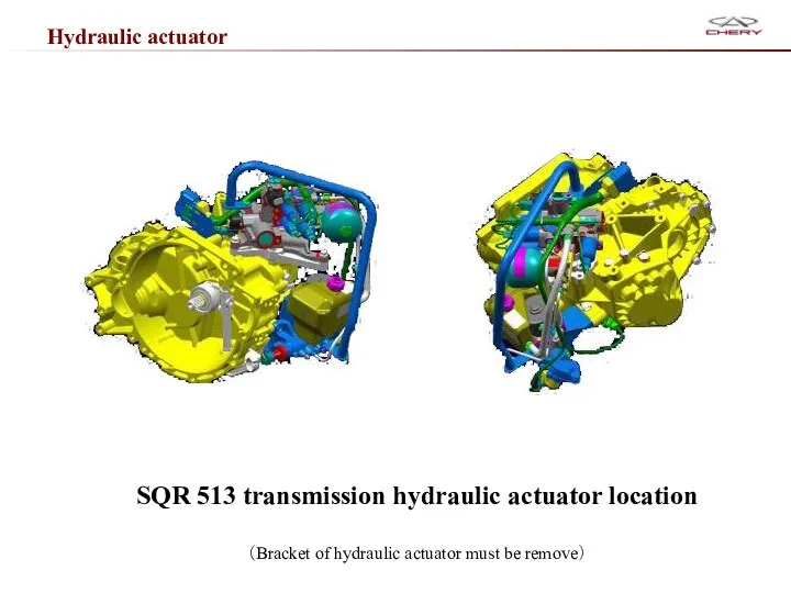
Hydraulic actuator
SQR 513 transmission hydraulic actuator location
(Bracket of hydraulic actuator must
Hydraulic actuator
SQR 513 transmission hydraulic actuator location
(Bracket of hydraulic actuator must

Power Unit
Hydraulic power unit provides power to hydraulic.
Motor
Accumulator
Gear pump
Low pressure fluid
Power Unit
Hydraulic power unit provides power to hydraulic.
Motor
Accumulator
Gear pump
Low pressure fluid

Pump
12V DC。
System pressure:
<36 bar run
>46 bar stop
TCU
30
31
Pump
12V DC。
System pressure:
<36 bar run
>46 bar stop
TCU
30
31

Tank
150 micrometer filter was fitted in exports of tank.
Fluid level standard
Relief
Tank
150 micrometer filter was fitted in exports of tank.
Fluid level standard
Relief

Accumulator
Capacity:250 cm3
Accumulator
Capacity:250 cm3

Valve body
Valve body has follow functions:
Control gear engage and detach。
Control gear
Valve body
Valve body has follow functions:
Control gear engage and detach。
Control gear
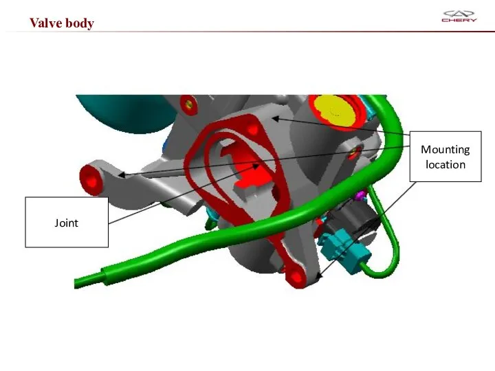
Valve body
Joint
Mounting location
Valve body
Joint
Mounting location
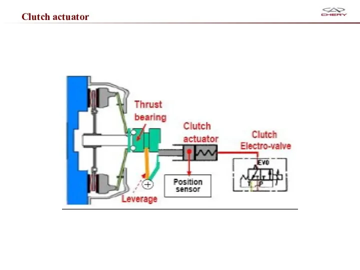
Clutch actuator
Clutch actuator
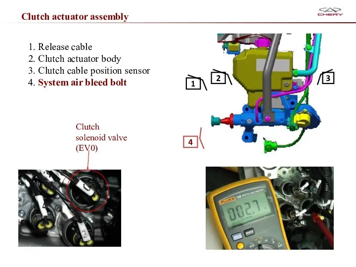
Clutch actuator assembly
1. Release cable
2. Clutch actuator body
3. Clutch cable position
Clutch actuator assembly
1. Release cable
2. Clutch actuator body
3. Clutch cable position

Data stream in X431 concerning clutch
Data stream in X431 concerning clutch

Clutch cable position sensor
Function: feedback the clutch cable position signal to
Clutch cable position sensor
Function: feedback the clutch cable position signal to

Gear engage and selection solenoid valves
Gear engage and selection solenoid valves
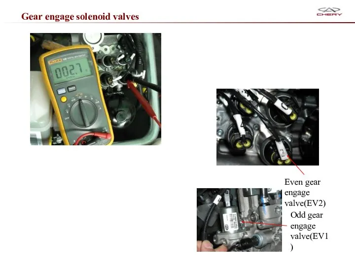
Gear engage solenoid valves
Even gear engage valve(EV2)
Odd gear engage valve(EV1)
Gear engage solenoid valves
Even gear engage valve(EV2)
Odd gear engage valve(EV1)

Gear selection valves
1-2 gears selection solenoid valve(EV3)
5-R gears selection solenoid valve(EV4)
Gear selection valves
1-2 gears selection solenoid valve(EV3)
5-R gears selection solenoid valve(EV4)

Summary of solenoid valves
Summary of solenoid valves

Pressure sensor
Function :Monitor system pressure
Pressure sensor
Function :Monitor system pressure
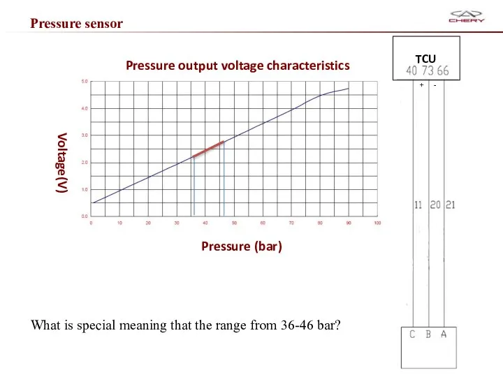
Pressure sensor
What is special meaning that the range from 36-46 bar?
TCU
Pressure sensor
What is special meaning that the range from 36-46 bar?
TCU

Maintenance specification
——AMT system self-learn
Maintenance specification
——AMT system self-learn
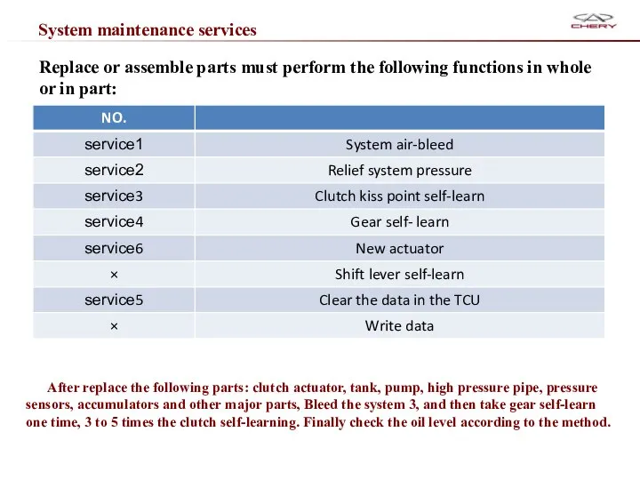
System maintenance services
Replace or assemble parts must perform the following functions
System maintenance services
Replace or assemble parts must perform the following functions

Service should be taken after parts replacement
Service should be taken after parts replacement

——Guide of dismount and assemble
Maintenance specification
——Guide of dismount and assemble
Maintenance specification
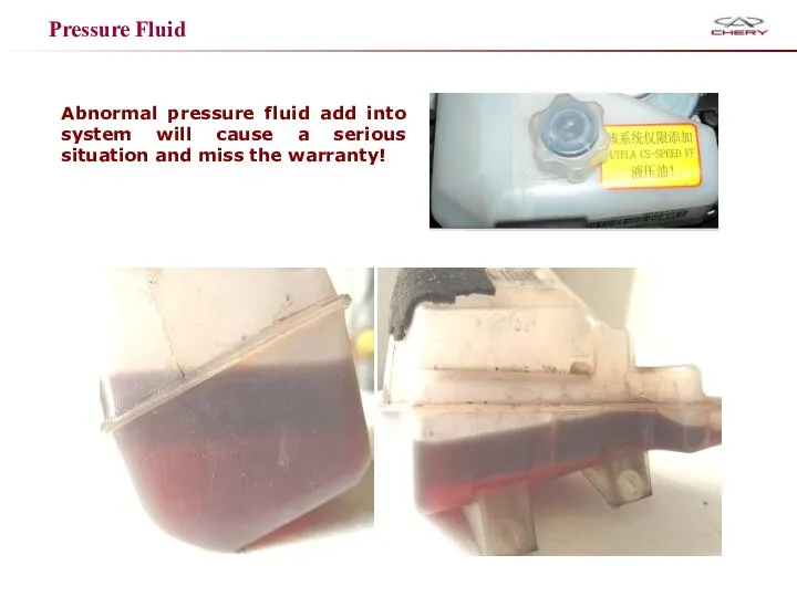
Pressure Fluid
Abnormal pressure fluid add into system will cause a serious
Pressure Fluid
Abnormal pressure fluid add into system will cause a serious

Before removing the AMT ASSM, selection shaft must be released. Remove
Before removing the AMT ASSM, selection shaft must be released. Remove

Mount guide
First of all, after cleaning and coating sealant,
should ensure
Mount guide
First of all, after cleaning and coating sealant,
should ensure
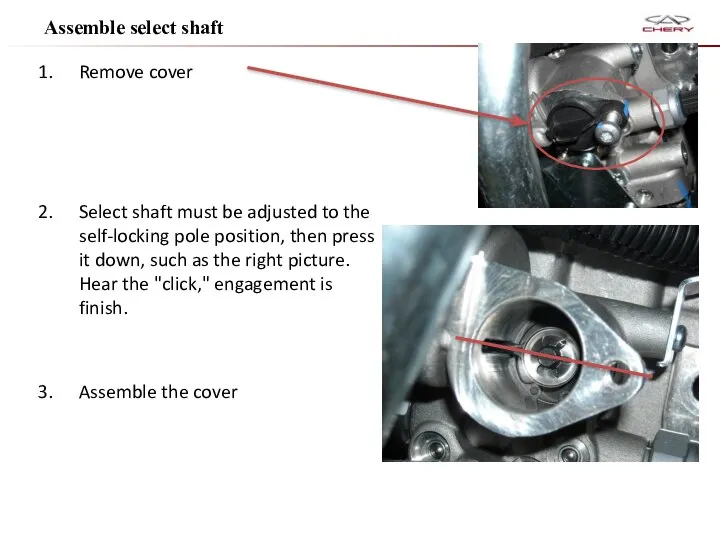
Remove cover
Select shaft must be adjusted to the self-locking pole position,
Remove cover
Select shaft must be adjusted to the self-locking pole position,

Fault code
Fault code
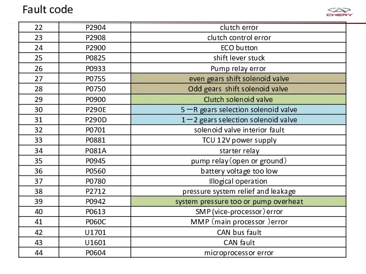
Fault code
Fault code
Trouble-shooting and solutions
Trouble-shooting and solutions

Problem I: The vehicle shivers noticeably upon releasing the accelerator pedal
Problem I: The vehicle shivers noticeably upon releasing the accelerator pedal

Problem II: The transmission failure lamp is lit during movement, and
Problem II: The transmission failure lamp is lit during movement, and

Problem III: Friction disc revolution sensor failure; the gear is locked
Problem III: Friction disc revolution sensor failure; the gear is locked

4. Clutch position sensor failure (in this case, P1810 and P0715
4. Clutch position sensor failure (in this case, P1810 and P0715
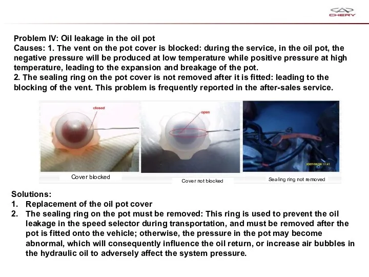
Problem IV: Oil leakage in the oil pot
Causes: 1. The
Problem IV: Oil leakage in the oil pot
Causes: 1. The

Problem V: There is trip stop or failure of gear engagement
Problem V: There is trip stop or failure of gear engagement
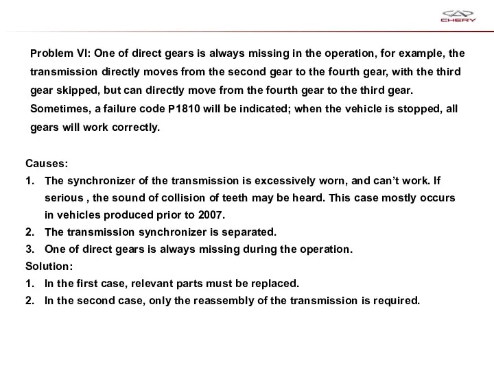
Problem VI: One of direct gears is always missing in the
Problem VI: One of direct gears is always missing in the

Problem VII
1. No depression of the accelerator pedal is required
Problem VII
1. No depression of the accelerator pedal is required
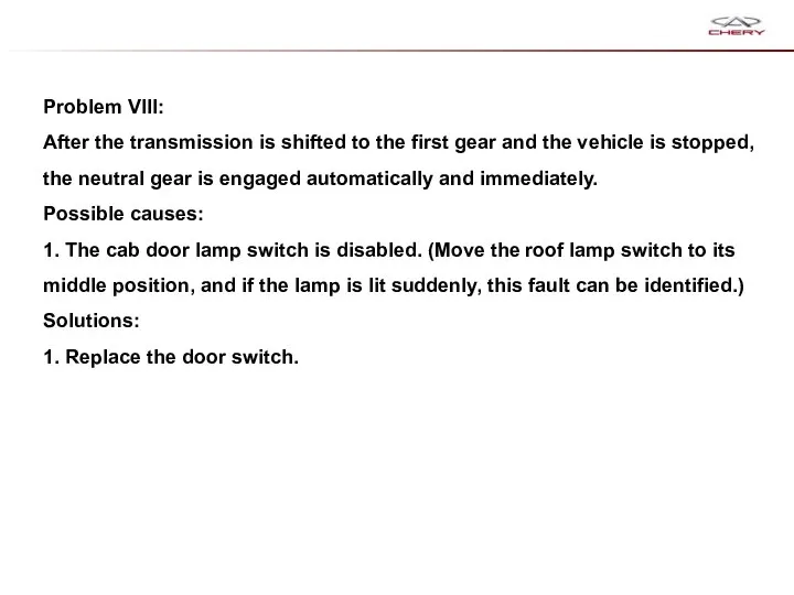
Problem VIII:
After the transmission is shifted to the first gear
Problem VIII:
After the transmission is shifted to the first gear

Thank you very much!
Thank you very much!

Pratice
Check resistence of each solenoid valve。
Remove gear selection/gear engage sensor/ clutch
Pratice
Check resistence of each solenoid valve。
Remove gear selection/gear engage sensor/ clutch
 «Граф. Построение графов»
 Презентация на тему "Веганы" - скачать презентации по Медицине
 Что продавать в кризис. Как выбрать нишу для бизнеса?
 Презентация "Русский модерн в живописи" - скачать презентации по МХК
 Способы преобразования проекций (Лекция 3)
 Народы Норвегии
  Тропинки здоровья кружка «Становление»
 Способы организации памяти для хранения данных
 Уголовное право Ирана
 Программирование и разработка веб-приложений. Использование Python для работы с базой данных
 Презентация на тему "Экологическое воспитание младших школьников" - скачать презентации по Педагогике
 ВЕКСЕЛЬ И ВЕКСЕЛЬНОЕ ОБРАЩЕНИЕ Функции и виды векселей Общая характеристика векселя как ценной бумаги Понятия, используемые
 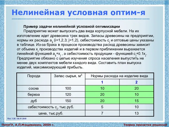 Нелинейная условная оптимизация
 Массивы, коллекции (лабораторные работы)
 Инженерные системы зданий и сооружений
 Фронтальная перспектива в архитектуре
 Презентация на тему "Розвиток критичного та креативного мислення на уроках особистісно зорієнтованого навчання." - скачать п
 Структурні елементи науки
 Презентация "Стилевое многообразие искусства XVII-XVIII веков" - скачать презентации по МХК
 Робот, которому захотелось спать - презентация для начальной школы
 Основы алгоритмики. Объектно-ориентированный подход
 Стратегия развития информационного общества в Российской Федерации Подготовила студентка 3 курса Группы Ю-123б Полина Колесни
 Презентация "Всемирный банк в Казахстане" - скачать презентации по Экономике
 Презентация "Виды и способы торговли" - скачать презентации по Экономике
 Преемственность наследственности в ряду поколений 5
 Генеральный прокурор Республики Казахстан Асхат Даулбаев
 Брестская область. Объект №73 (комплексная база для всех видов спорта)
 Презентация "История музыки" - скачать презентации по МХК