- Exercises. Analog module

Содержание
- 2. 6 – Analog module Goal : Use an Analog Input ( BMX AMI 0410 ) and
- 3. Solution
- 4. 6 – Analog modules Wiring 0v 24v 1 2 VOIE0 BMX AMI 0410 BMX AMI 0410
- 5. 6 – Analog module Configuration Methodology : Realize the configuration for the BMX AMI 0410 in
- 6. 6 – Analog modules Programming Create a DFB ‘VALVE’ With : - 2 inputs - 1
- 7. 6 – Analog modules Programming Create a FBD section named “Ex_7” Convert In_Ana1.value as an REAL
- 8. 6 – Analog modules Possible solution
- 10. Скачать презентацию
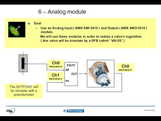
6 – Analog module
Goal :
Use an Analog Input ( BMX AMI
6 – Analog module
Goal :
Use an Analog Input ( BMX AMI
Solution
Solution

6 – Analog modules
Wiring
0v
24v
1
2
VOIE0
BMX AMI 0410
BMX AMI 0410
BMX AMI0 0210
This
6 – Analog modules
Wiring
0v
24v
1
2
VOIE0
BMX AMI 0410
BMX AMI 0410
BMX AMI0 0210
This

6 – Analog module
Configuration Methodology :
Realize the configuration for the BMX
6 – Analog module
Configuration Methodology :
Realize the configuration for the BMX

6 – Analog modules
Programming
Create a DFB ‘VALVE’
With :
- 2
6 – Analog modules
Programming
Create a DFB ‘VALVE’
With :
- 2

6 – Analog modules
Programming
Create a FBD section named “Ex_7”
Convert In_Ana1.value as
6 – Analog modules
Programming
Create a FBD section named “Ex_7”
Convert In_Ana1.value as

6 – Analog modules
Possible solution
6 – Analog modules
Possible solution
 Русско-Турецкая война 1806-1812
 Дом снаружи и внутри. Урок ИЗО 1 класс
 МОТИВАЦИОННАЯ ТЕОРИЯ А. МАСЛОУ
 State of India - Kashmir
 СИСТЕМА ЗДРАВООХРАНЕНИЯ ГЕРМАНИИ И ФРАНЦИИ Школа качества и управления Занятие 11 Отдел маркетинга и инноваций
 Аттестационная работа. Программа духовно-нравственного воспитания «От истоков к современности» (5-9 классы
 Микроскопический анализ металлов
 Коммуникации в проектах
 ЗАГАДКА "Собака" - презентация для начальной школы_
 Субъекты социального обеспечения
 Презентация____
 Дидактичні завдання з української мови (3 клас)
 Древняя архитектура Первоэлементы архитектуры; Цивилизации Древней Америки; Семь чудес света; - Великие Египетские пирамид
 Экстремизм и терроризм: основные понятия и причины его возникновения
 Введение в ПОР. Основные теоретические вопросы проектирования ПОР
 презентация по микроэкономике с использованием статистических баз официальных сайтов
  Волейбол
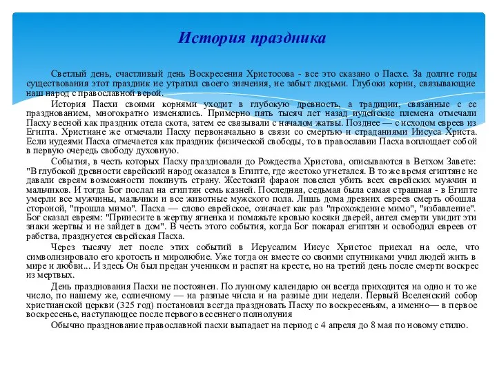 История праздника Пасха
 Передвиборча програма кандидата на посаду голови студентської ради Полтавського національного педагогічного університету
 Тематическая ( сюжетная) картина
 Взрывная травма. Повреждения при взрывах. Выполнили: Студенты 4-го курса Меженько Ю.В и Уварова В.Н
 Калькулятор. Принцип работі
 Помни правила движения, как таблицу умножения! - презентация для начальной школы
 Lectia de educatie fizica si sport
 Кибернетика
  Евроклуб При 78 СОУ “Христо Смирненски”
 Презентация "Андрей Рублёв (10 класс)" - скачать презентации по МХК
 Общая физиология возбудимых систем