- Features that are available only in the Advanced version: 3D simulation

Содержание
- 2. 3D Simulation The wire-frame 3D simulation allows to display on the PC the real machining process,
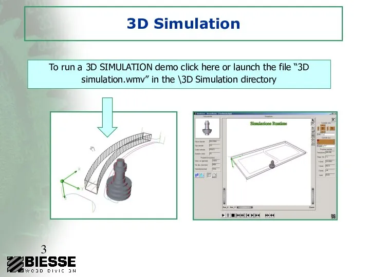
- 3. 3D Simulation To run a 3D SIMULATION demo click here or launch the file “3D simulation.wmv”
- 4. Pocketing and text engraving Automatic calculation of the tool routes necessary for the performance of automatic
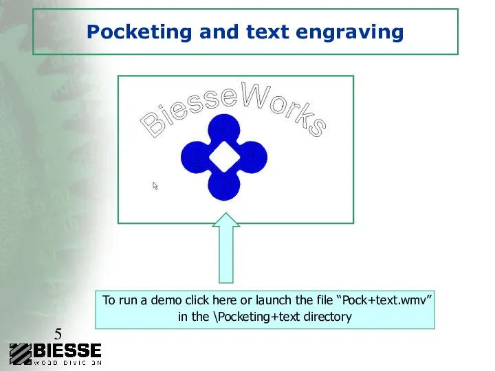
- 5. Pocketing and text engraving To run a demo click here or launch the file “Pock+text.wmv” in
- 6. Sides defined by the operator Creation of linear and circular sides defined by the operator in
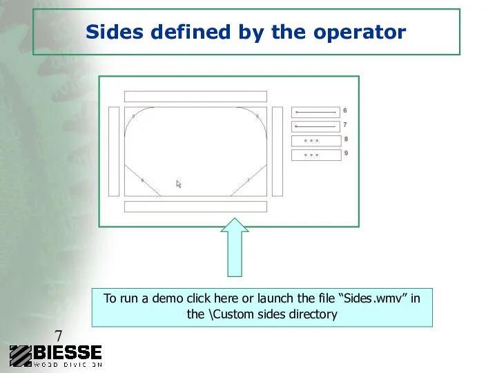
- 7. Sides defined by the operator To run a demo click here or launch the file “Sides.wmv”
- 8. Parametric Work Table Tooling Creation of parametric rules for the positioning of locking devices, so that
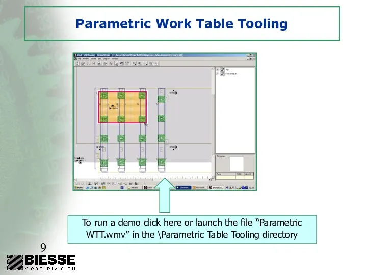
- 9. Parametric Work Table Tooling To run a demo click here or launch the file “Parametric WTT.wmv”
- 10. Chip deflector Chip deflector programming
- 11. Edge banding Easy and friendly programming for the edge banding and finishing process Tools for the
- 12. Edge banding
- 14. Скачать презентацию
3D Simulation
The wire-frame 3D simulation allows to display on the
3D Simulation
The wire-frame 3D simulation allows to display on the
3D Simulation
To run a 3D SIMULATION demo click here or launch
3D Simulation
To run a 3D SIMULATION demo click here or launch
Pocketing and text engraving
Automatic calculation of the tool routes necessary
Pocketing and text engraving
Automatic calculation of the tool routes necessary
Pocketing and text engraving
To run a demo click here or launch
Pocketing and text engraving
To run a demo click here or launch
Sides defined by the operator
Creation of linear and circular sides
Sides defined by the operator
Creation of linear and circular sides
Sides defined by the operator
To run a demo click here or
Sides defined by the operator
To run a demo click here or
Parametric Work Table Tooling
Creation of parametric rules for the
Parametric Work Table Tooling
Creation of parametric rules for the
Parametric Work Table Tooling
To run a demo click here or launch
Parametric Work Table Tooling
To run a demo click here or launch
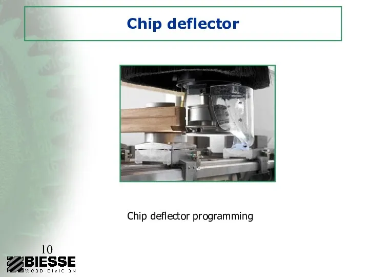
Chip deflector
Chip deflector programming
Chip deflector
Chip deflector programming
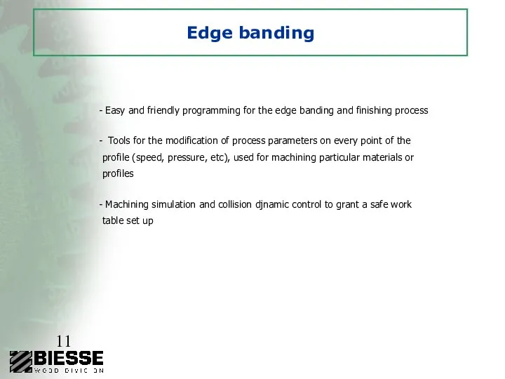
Edge banding
Easy and friendly programming for the edge banding and
Edge banding
Easy and friendly programming for the edge banding and
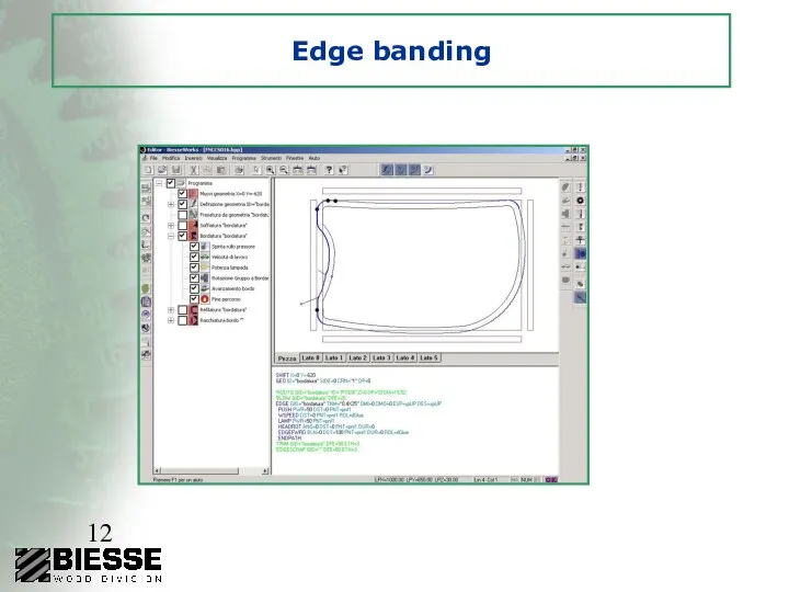
Edge banding
Edge banding
 Наши национальные денежные знаки - презентация для начальной школы_
 Обробка інформації в обліковій системі
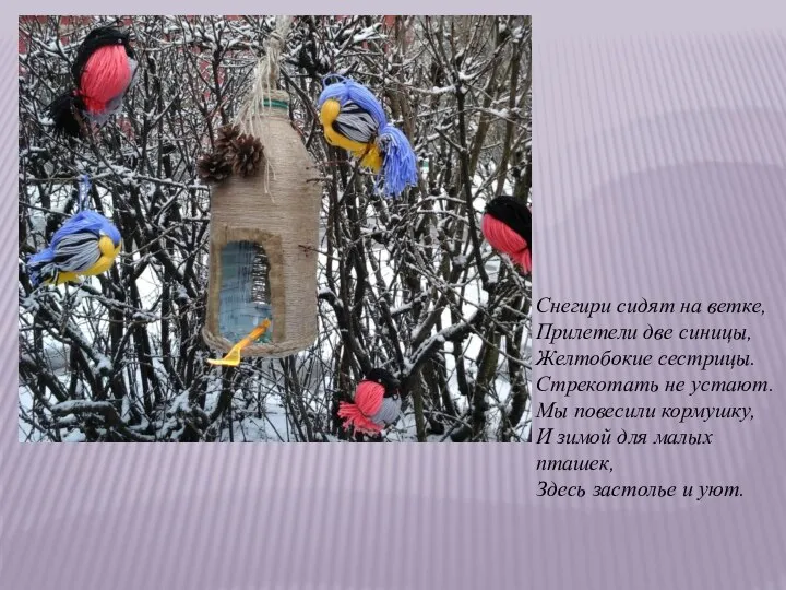 Кормушки для птиц
 кредитно-денежная система
 P-Урок 04 Равномерное прямолинейное движение
 Кафедра микробиологии, вирусологии и иммунологии КазНМУ Электронное пособие на тему: Алгоритм лабораторной диагностики уроге
 Лесли Алвин Уайт
 Чарльз Роберт Дарвин: фрагменты жизни
 Разработка Internet- и Web-приложений. Изучаем JavaScript. (Лекция 4)
 Event-менеджмент Выполнили Симбирская О. В. , Шаляпина О. Н., МАОУ «Гимназия №2» В. Новгород 2012 год
 Презентация "УПРАВЛЕНИЕ КАЧЕСТВОМ логистических процессов" - скачать презентации по Экономике
 Обработка ошибок
 Organization of the Diplomatic protocol in Italy
 Производственная практика. ООО «Сибирская ярмарка»
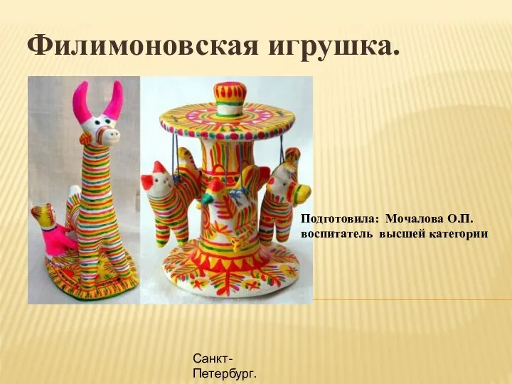 Филимоновская игрушка
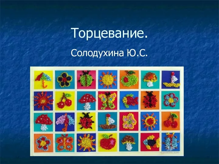 Техника торцевания
 Содержание курса - Как стать успешным в XXI веке?Содержание курса Эти навыки дает программа «Учимся с INTEL» - 15 занятий! Расписание зан
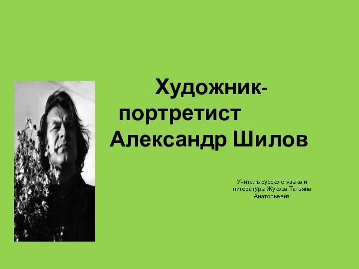 Художник- портретист Александр Шилов Учитель русского языка и литературы Жукова Татьяна Анатольевна
 Нейрофизиология программы
  Винайдення автобуса
 ГЕОЛОГИЧЕСКАЯ ДЕЯТЕЛЬНОСТЬ РЕК И ВРЕМЕННЫХ ПОТОКОВ
 Нейронная регуляция 1. Отличие нейронной регуляции от гуморальной. 2. Рефлекторный принцип регуляции. 3. Физиологическая харак
 Интеграция различных подходов к менеджменту Выполнил: Студент 41 БЖД Гильматдинов М.М.
 Договор синдицированного кредита по российскому праву Иван Борисов Vice President, Legal counsel
  Художник-воин-патриот Монографический урок по творчеству Василия Васильевича Верещагина 1842-1904
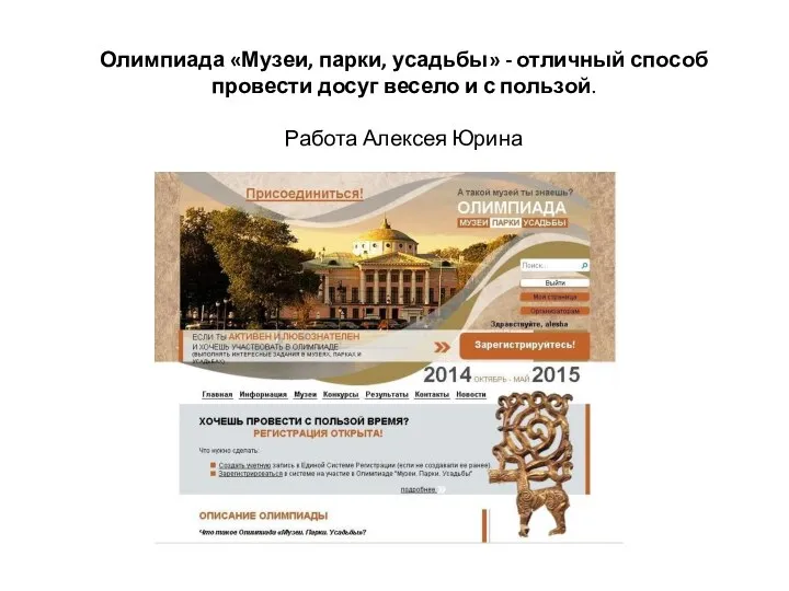 Музеи. Парки. Усадьбы
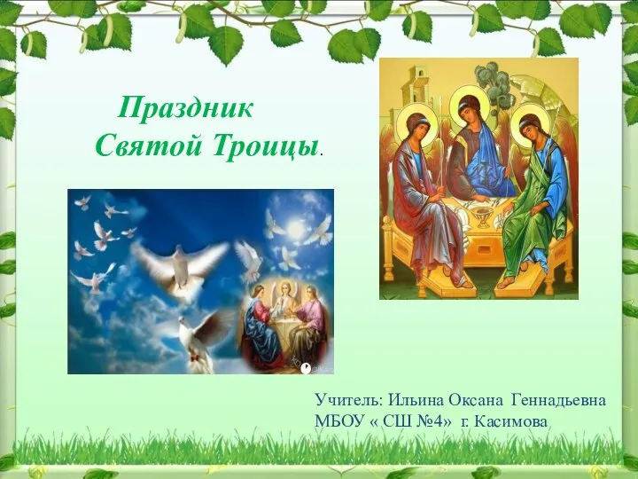 Праздник Святой Троицы
 История возникновения петербургской росписи