- Composites in the growing field of carbon nanotubes and other carbon nano-forms

Содержание
- 2. Initial studies in carbon nanotubes and nanoclay modified composites Cytec Engineering Materials. CYCOM 977-20, 177˚C curing
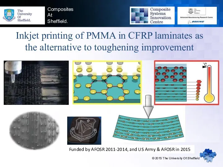
- 3. Composites At Sheffield. Inkjet printing of PMMA in CFRP laminates as the alternative to toughening improvement
- 4. Shear Modulus & ILSS Fibre-reinforced plastic composites — Determination of apparent interlaminar shear strength by short-beam
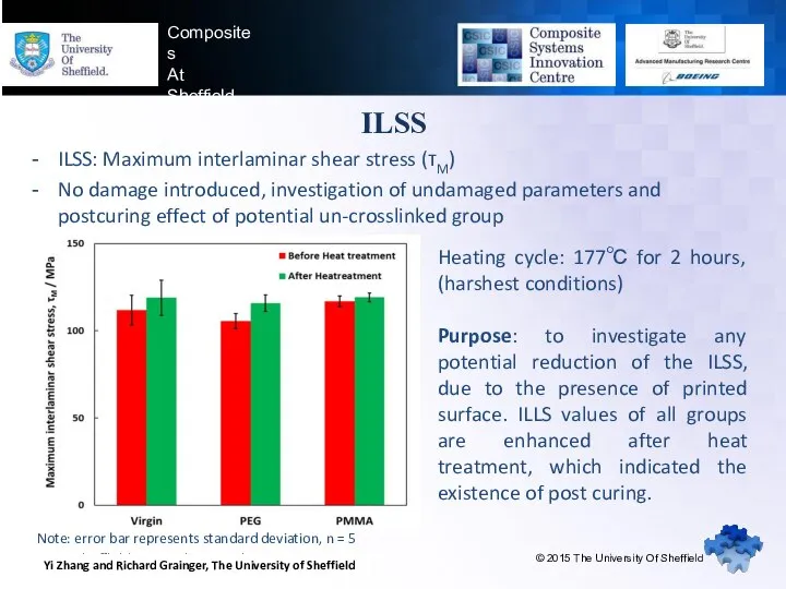
- 5. www.sheffieldcomposites.co.uk Composites At Sheffield ILSS ILSS: Maximum interlaminar shear stress (τM) No damage introduced, investigation of
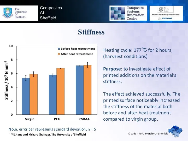
- 6. www.sheffieldcomposites.co.uk Composites At Sheffield. Stiffness © 2015 The University Of Sheffield Heating cycle: 177℃ for 2
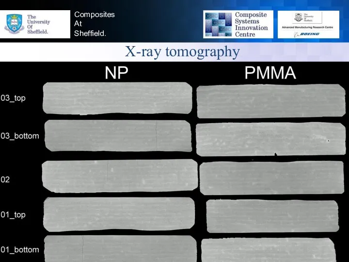
- 7. www.sheffieldcomposites.co.uk Composites At Sheffield. X-ray tomography © 2013 The University Of Sheffield
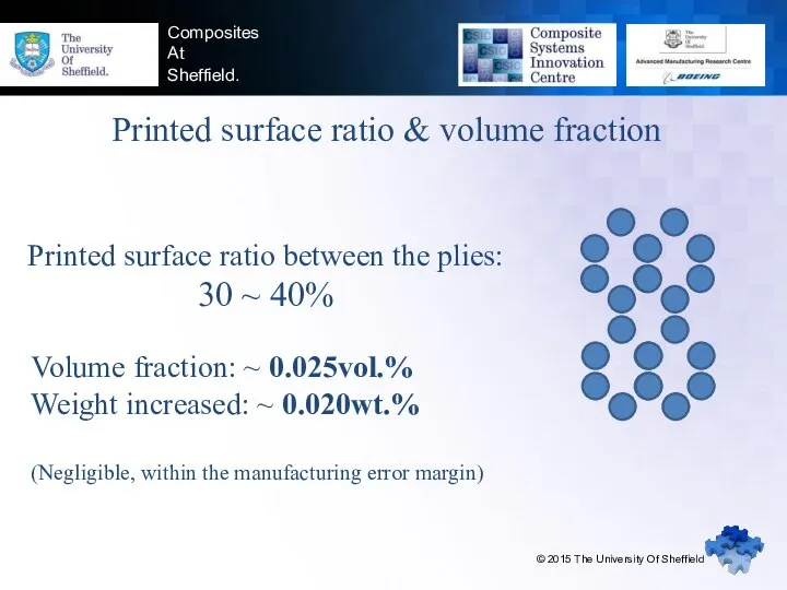
- 8. Composites At Sheffield. Printed surface ratio & volume fraction Volume fraction: ~ 0.025vol.% Weight increased: ~
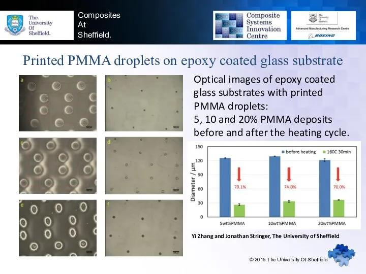
- 9. Composites At Sheffield. Printed PMMA droplets on epoxy coated glass substrate © 2015 The University Of
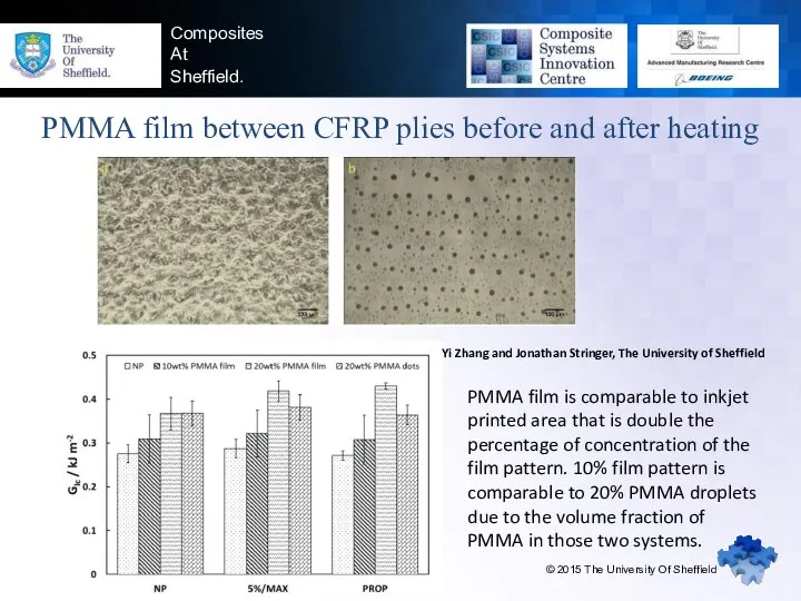
- 10. Composites At Sheffield. PMMA film between CFRP plies before and after heating © 2015 The University
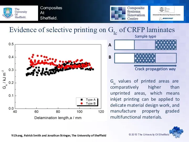
- 11. © 2015 The University Of Sheffield Composites At Sheffield. Evidence of selective printing on GIc of
- 12. Composites At Sheffield. PMMA contribution to CFRP properties © 2015 The University Of Sheffield PMMA droplets
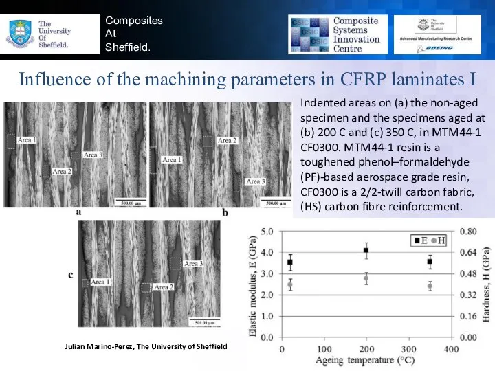
- 13. Composites At Sheffield. Influence of the machining parameters in CFRP laminates I © 2015 The University
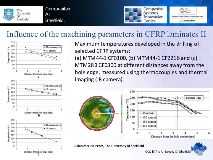
- 14. Composites At Sheffield. Influence of the machining parameters in CFRP laminates II © 2015 The University
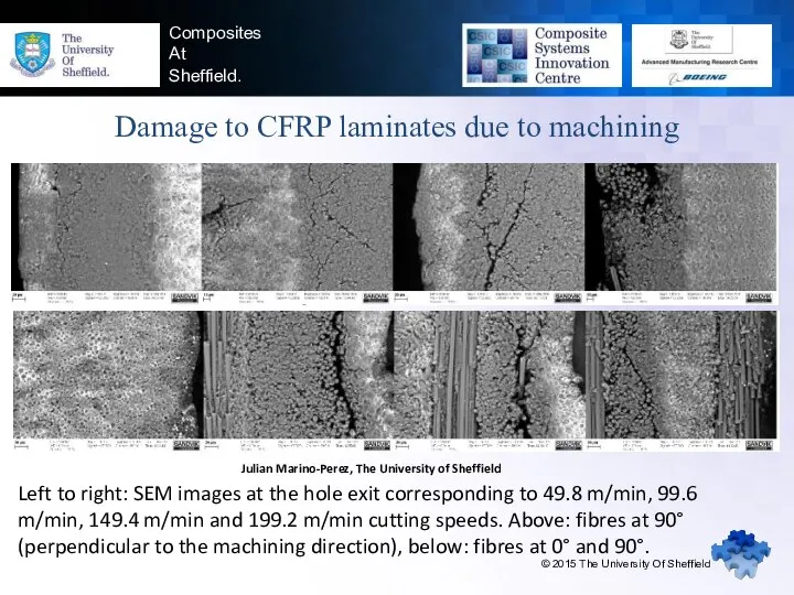
- 15. Composites At Sheffield. Damage to CFRP laminates due to machining © 2015 The University Of Sheffield
- 17. Скачать презентацию
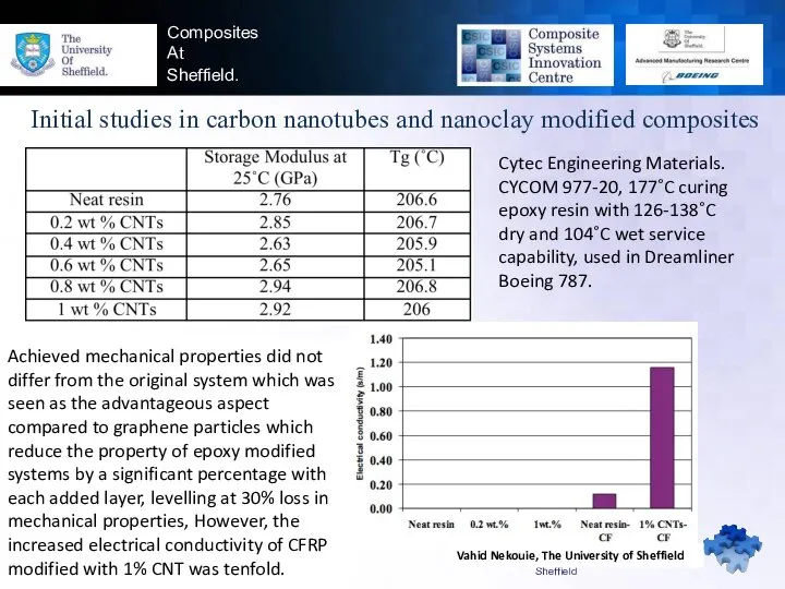
Initial studies in carbon nanotubes and nanoclay modified composites
Cytec Engineering Materials.
Initial studies in carbon nanotubes and nanoclay modified composites
Cytec Engineering Materials.
Composites
At
Sheffield.
Inkjet printing of PMMA in CFRP laminates as the
Composites
At
Sheffield.
Inkjet printing of PMMA in CFRP laminates as the
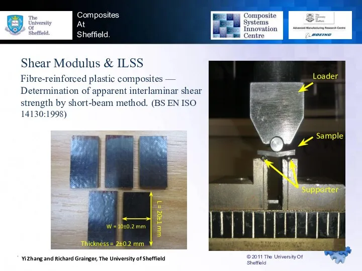
Shear Modulus & ILSS
Fibre-reinforced plastic composites — Determination of apparent interlaminar
Shear Modulus & ILSS
Fibre-reinforced plastic composites — Determination of apparent interlaminar
www.sheffieldcomposites.co.uk
Composites
At
Sheffield
ILSS
ILSS: Maximum interlaminar shear stress (τM)
No damage introduced, investigation
www.sheffieldcomposites.co.uk
Composites
At
Sheffield
ILSS
ILSS: Maximum interlaminar shear stress (τM)
No damage introduced, investigation
www.sheffieldcomposites.co.uk
Composites
At
Sheffield.
Stiffness
© 2015 The University Of Sheffield
Heating cycle: 177℃ for
www.sheffieldcomposites.co.uk
Composites
At
Sheffield.
Stiffness
© 2015 The University Of Sheffield
Heating cycle: 177℃ for
www.sheffieldcomposites.co.uk
Composites
At
Sheffield.
X-ray tomography
© 2013 The University Of Sheffield
www.sheffieldcomposites.co.uk
Composites
At
Sheffield.
X-ray tomography
© 2013 The University Of Sheffield
Composites
At
Sheffield.
Printed surface ratio & volume fraction
Volume fraction: ~ 0.025vol.%
Weight
Composites
At
Sheffield.
Printed surface ratio & volume fraction
Volume fraction: ~ 0.025vol.%
Weight
Composites
At
Sheffield.
Printed PMMA droplets on epoxy coated glass substrate
© 2015
Composites
At
Sheffield.
Printed PMMA droplets on epoxy coated glass substrate
© 2015
Composites
At
Sheffield.
PMMA film between CFRP plies before and after heating
©
Composites
At
Sheffield.
PMMA film between CFRP plies before and after heating
©
© 2015 The University Of Sheffield
Composites
At
Sheffield.
Evidence of selective printing
© 2015 The University Of Sheffield
Composites
At
Sheffield.
Evidence of selective printing
Composites
At
Sheffield.
PMMA contribution to CFRP properties
© 2015 The University Of
Composites
At
Sheffield.
PMMA contribution to CFRP properties
© 2015 The University Of
Composites
At
Sheffield.
Influence of the machining parameters in CFRP laminates I
Composites
At
Sheffield.
Influence of the machining parameters in CFRP laminates I
Composites
At
Sheffield.
Influence of the machining parameters in CFRP laminates II
Composites
At
Sheffield.
Influence of the machining parameters in CFRP laminates II
Composites
At
Sheffield.
Damage to CFRP laminates due to machining
© 2015 The
Composites
At
Sheffield.
Damage to CFRP laminates due to machining
© 2015 The
 Дисперсиялык талдаудын бір факторлы параметрлік емес үқсастығы критерий - Крускал Уоллис критерийі
 Радиактивность
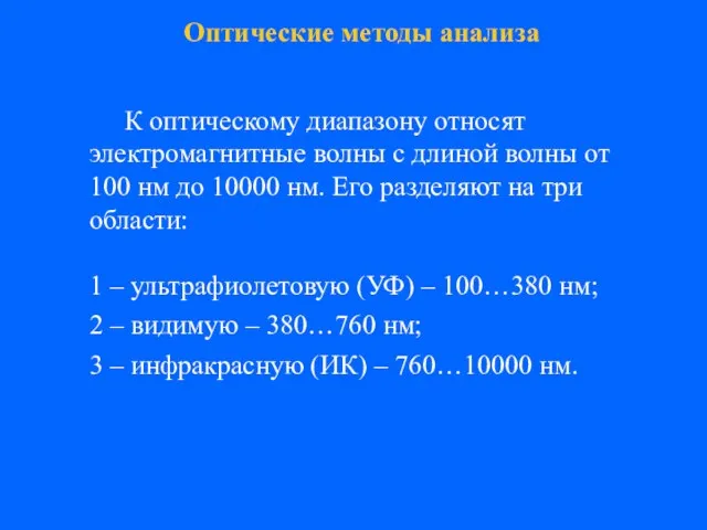 Оптические методы анализа
 Измерение показателей преломления жидкостей и твердых сред на рефрактометрах (ЛР №3)
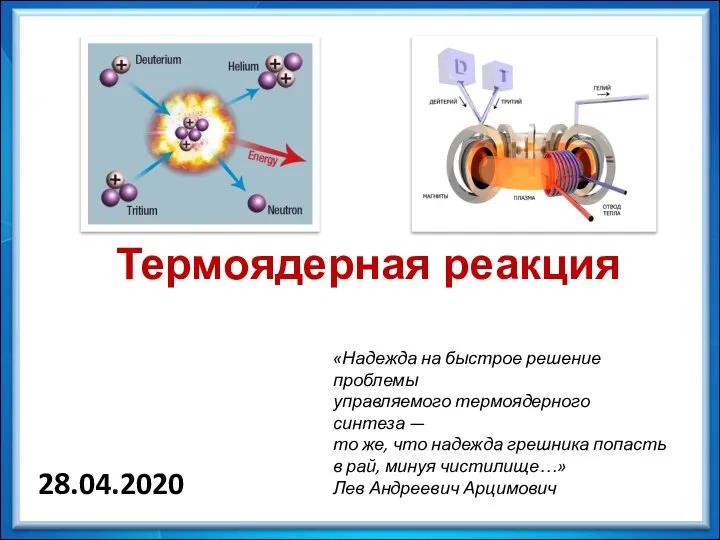 Термоядерная реакция
 Строение атомного ядра
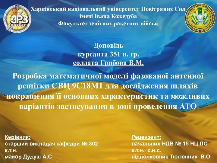 Розробка математичної моделі фазованої антенної решітки СВЦ 9С18М1
 Магнитное и электрическое поле. Введение
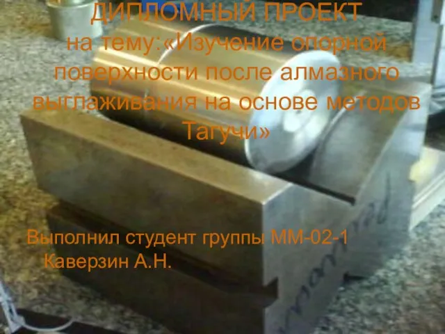 Изучение опорной поверхности после алмазного выглаживания на основе методов Тагучи
 Относительность движения
  Электромагнетизм
 Машиноведение. История, устройство и использование швейных машин
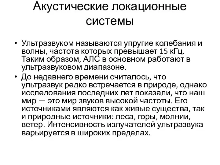 Акустические локационные системы
 Достоинство и недостатки тепловых двигателей
 Электродинамика. Электростатика
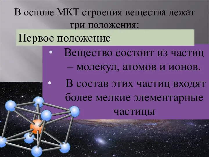 МКТ. Строение вещества
 Кольца Гельмгольца
 Закон сохранения заряда. Закон Кулона
 Механика. Сплошная среда
 Цифровые ключи на биполярных транзисторах. Схемотехника, принципы работы, параметры и характеристики
 Измерение вершинных отрезков и рабочих расстояний
 Квантовые свойства света. Фотоэффект и его законы. Применение фотоэффекта в технике
 Плотность овощей и фруктов, выращиваемых на приусадебном участке МОУ “Средняя общеобразовательная школа № 1 с углублённым изучением английского языка”
 3. Первоначальные сведения об электрических явлениях. Электризация тел.
 Резка ножницами с параллельными ножами с гидравлическим приводом
 Поляризация диэлектриков. Электрическое поле в диэлектрике
 система конструирования отопительных устройств
 КАФЕДРА КАФЕДРА ИНФОРМАЦИОННЫХ ТЕХНОЛОГИЙ ТОПЛИВНО-ЭНЕРГЕТИЧЕСКОГО КОМПЛЕКСА