- Co-design and testing of safety-critical embedded systems

Содержание
- 2. 2 General course information 2. Prerequisites: Computer Systems and System Analysis; Foundations of Logic Engineering; Probability
- 3. Teaching and Learning Time Allocation Master Course. Co-Design and Testing of Safety-Critical Embedded Systems 3
- 4. MODULE 1. Co-design foundation of S-CES 4 Master Course. Co-Design and Testing of Safety-Critical Embedded Systems
- 5. MODULE 1. Co-Design Foundation of S-CES 5 Lecture 1. Traditional ideas of S-CES co-design 1.2. Standards
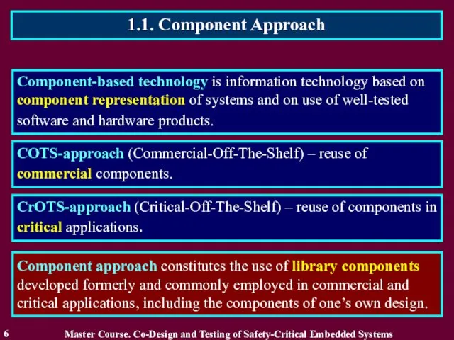
- 6. 1.1. Component Approach 6 Component-based technology is information technology based on component representation of systems and
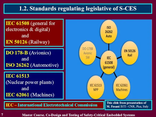
- 7. 1.2. Standards regulating legislative of S-CES 7 IEC 61508 (general for electronics & digital) and EN
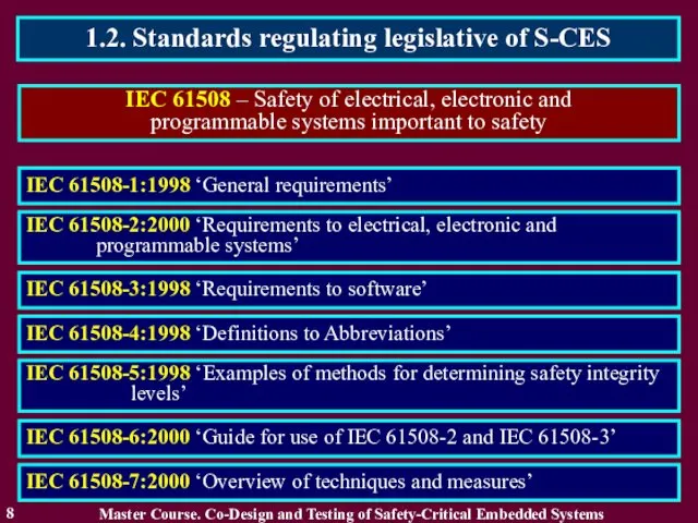
- 8. 1.2. Standards regulating legislative of S-CES 8 IEC 61508 – Safety of electrical, electronic and programmable
- 9. 1.2. Standards regulating legislative of S-CES 9 Features of IEC 61508 standard Master Course. Co-Design and
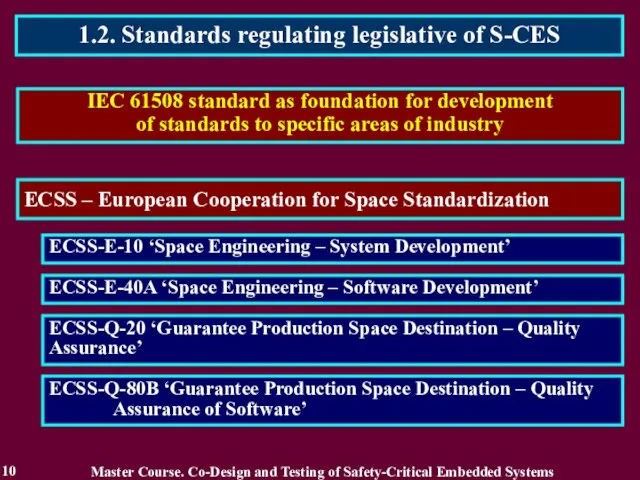
- 10. 1.2. Standards regulating legislative of S-CES 10 IEC 61508 standard as foundation for development of standards
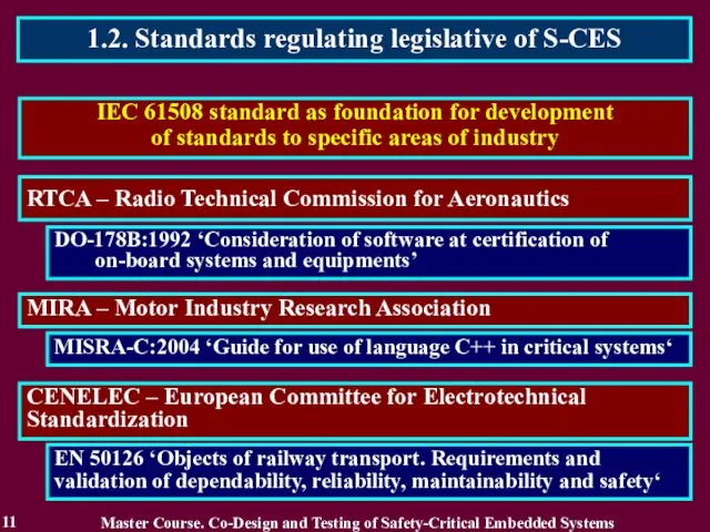
- 11. 1.2. Standards regulating legislative of S-CES 11 IEC 61508 standard as foundation for development of standards
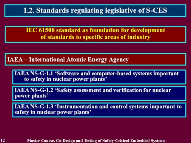
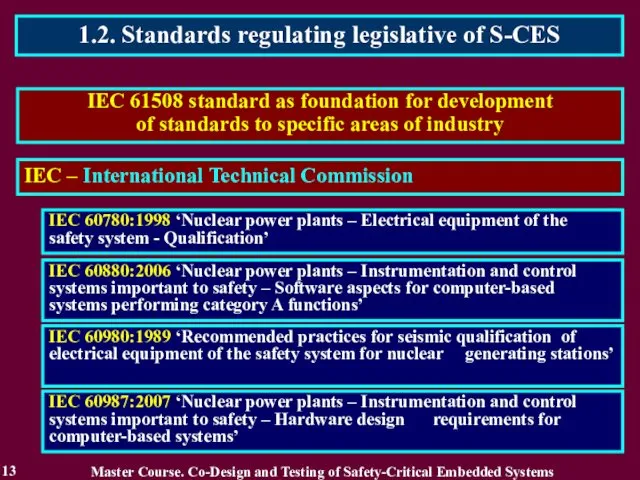
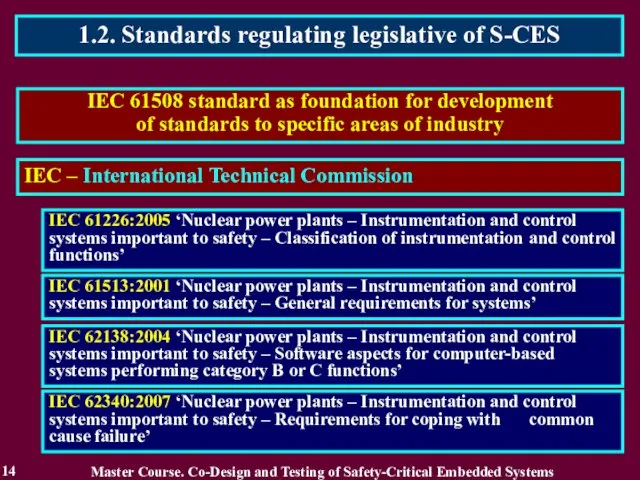
- 12. 1.2. Standards regulating legislative of S-CES 12 IEC 61508 standard as foundation for development of standards
- 13. 1.2. Standards regulating legislative of S-CES 13 IEC 61508 standard as foundation for development of standards
- 14. 1.2. Standards regulating legislative of S-CES 14 IEC 61508 standard as foundation for development of standards
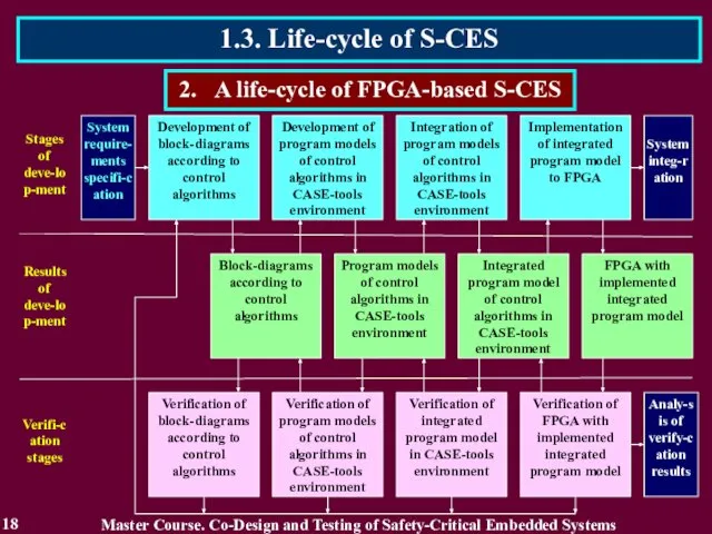
- 15. 1.3. Life-cycle of S-CES 15 1. Development of signal formation algorithm block-diagram. 1. Stages of FPGA-based
- 16. 1.3. Life-cycle of S-CES 16 1. Block-diagrams according to control algorithms. 2. Results of FPGA-based digital
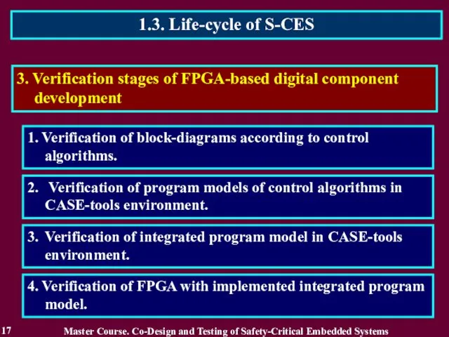
- 17. 1.3. Life-cycle of S-CES 17 1. Verification of block-diagrams according to control algorithms. 3. Verification stages
- 18. 1.3. Life-cycle of S-CES 18 2. A life-cycle of FPGA-based S-CES Master Course. Co-Design and Testing
- 19. Reading List 19 Master Course. Co-Design and Testing of Safety-Critical Embedded Systems Бахмач Е.С., Герасименко А.Д.,
- 20. Conclusion 20 2. Component approach constitutes the use of library components developed formerly and commonly employed
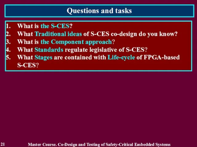
- 21. Questions and tasks 21 What is the S-CES? What Traditional ideas of S-CES co-design do you
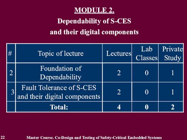
- 22. MODULE 2. Dependability of S-CES and their digital components Master Course. Co-Design and Testing of Safety-Critical
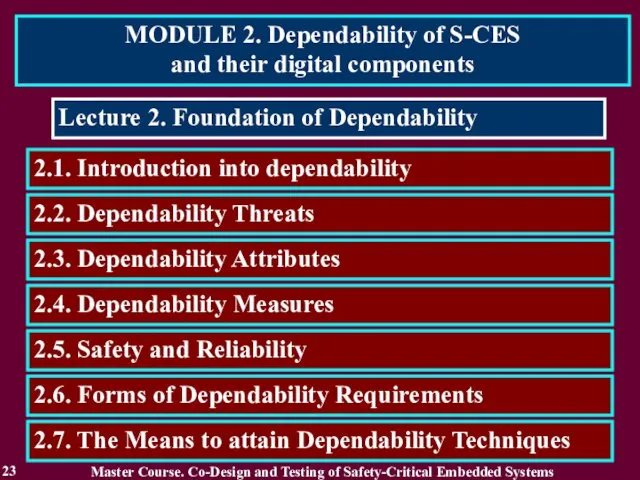
- 23. MODULE 2. Dependability of S-CES and their digital components 23 Lecture 2. Foundation of Dependability 2.2.
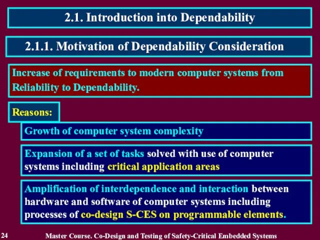
- 24. 2.1. Introduction into Dependability 24 Increase of requirements to modern computer systems from Reliability to Dependability.
- 25. 2.1.2. Related Works 25 Different aspects of Dependability, principles of construction and realization of dependable computer
- 26. 2.1.3. Definition of Dependability 26 Dependability is ability to avoid service failures that are more frequent
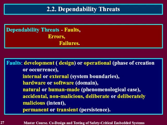
- 27. 2.2. Dependability Threats 27 Dependability Threats - Faults, Errors, Failures. Master Course. Co-Design and Testing of
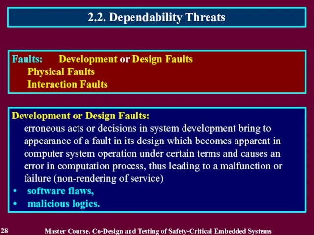
- 28. 2.2. Dependability Threats 28 Master Course. Co-Design and Testing of Safety-Critical Embedded Systems Faults: Development or
- 29. 2.2. Dependability Threats 29 Master Course. Co-Design and Testing of Safety-Critical Embedded Systems Physical Faults: due
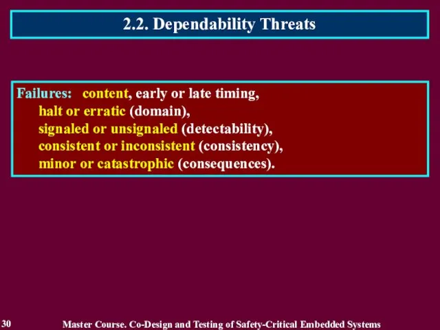
- 30. 2.2. Dependability Threats 30 Master Course. Co-Design and Testing of Safety-Critical Embedded Systems Failures: content, early
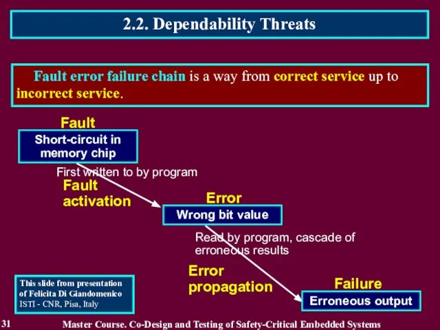
- 31. 2.2. Dependability Threats 31 Fault error failure chain is a way from correct service up to
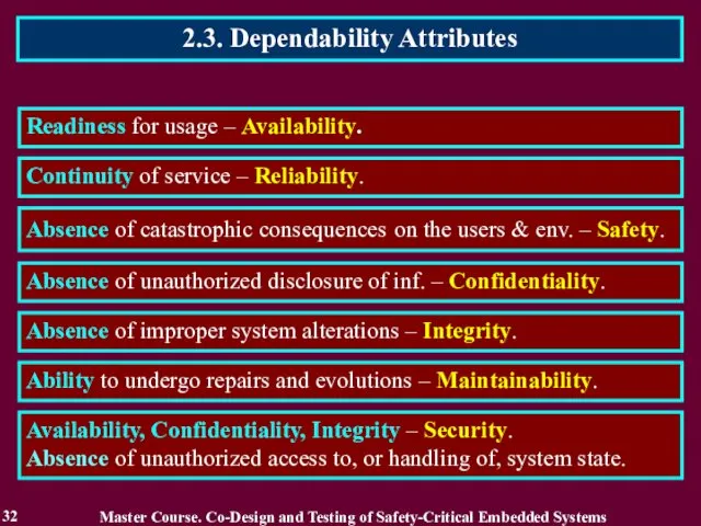
- 32. 2.3. Dependability Attributes 32 Readiness for usage – Availability. Continuity of service – Reliability. Absence of
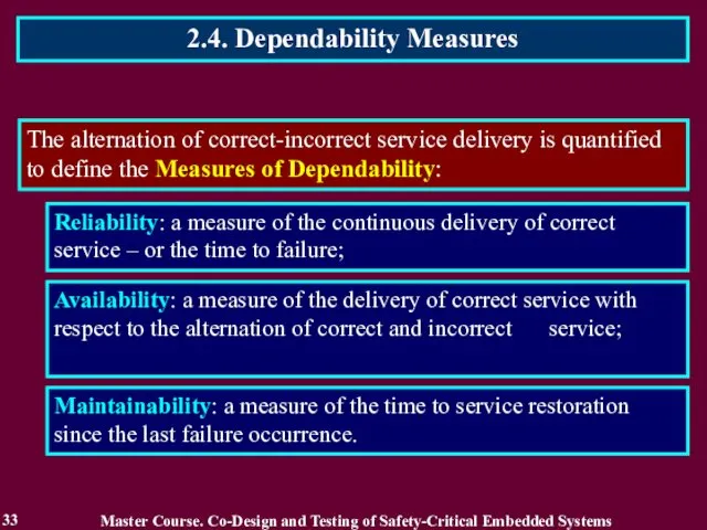
- 33. 2.4. Dependability Measures 33 The alternation of correct-incorrect service delivery is quantified to define the Measures
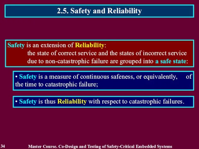
- 34. 2.5. Safety and Reliability 34 Safety is an extension of Reliability: the state of correct service
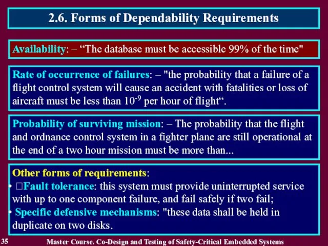
- 35. 2.6. Forms of Dependability Requirements 35 Availability: – “The database must be accessible 99% of the
- 36. 2.7. The Means to attain Dependability Techniques 36 The development of a Dependable Computing System calls
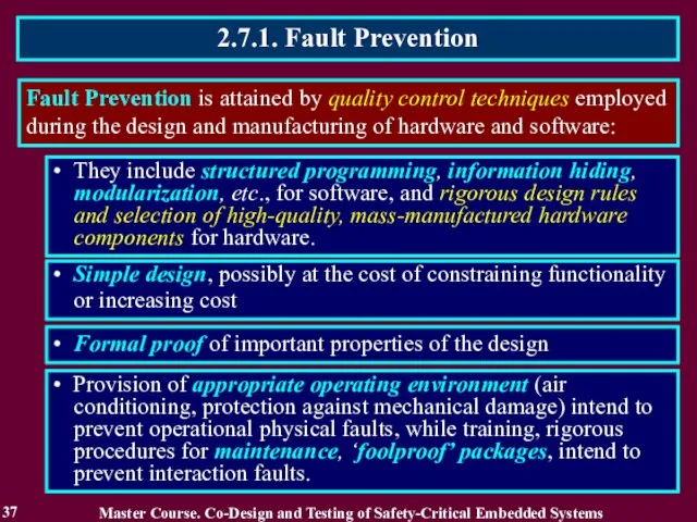
- 37. 2.7.1. Fault Prevention 37 Fault Prevention is attained by quality control techniques employed during the design
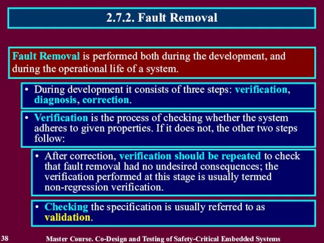
- 38. 2.7.2. Fault Removal 38 Fault Removal is performed both during the development, and during the operational
- 39. 2.7.2.1. Fault Removal during Development 39 Verification Techniques can be classified according to whether or not
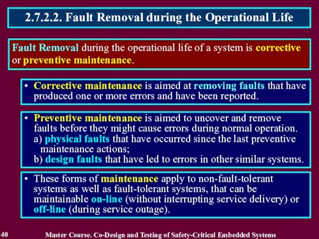
- 40. 2.7.2.2. Fault Removal during the Operational Life 40 Fault Removal during the operational life of a
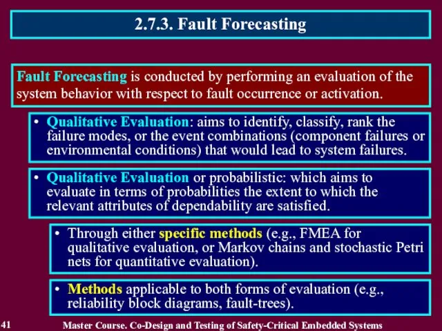
- 41. 2.7.3. Fault Forecasting 41 Fault Forecasting is conducted by performing an evaluation of the system behavior
- 42. Reading List 42 Master Course. Co-Design and Testing of Safety-Critical Embedded Systems Бахмач Е.С., Герасименко А.Д.,
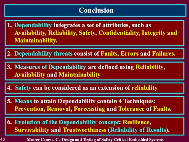
- 43. Conclusion 43 2. Dependability threats consist of Faults, Errors and Failures. 1. Dependability integrates a set
- 44. Questions and tasks 44 What is the Dependability? What Dependability threats of S-CES do you know?
- 45. MODULE 2. Dependability of S-CES and their digital components 45 Lecture 3. Fault Tolerance of S-CES
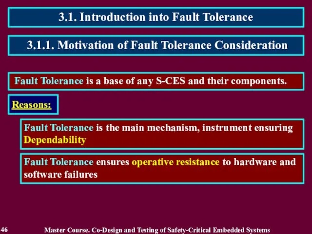
- 46. 3.1. Introduction into Fault Tolerance 46 Fault Tolerance is a base of any S-CES and their
- 47. 3.1.2. Related Works 47 Master Course. Co-Design and Testing of Safety-Critical Embedded Systems 1. Dobson I.,
- 48. 3.1.3. Definition of Fault Tolerance 48 Fault Tolerance is intended to preserve the delivery of correct
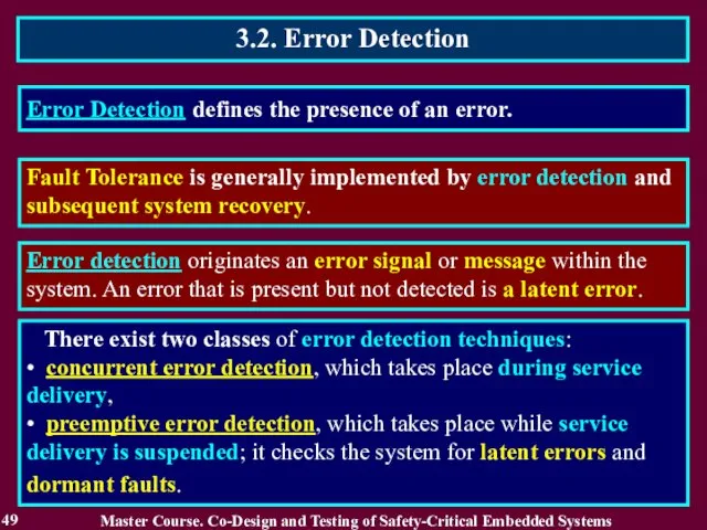
- 49. 3.2. Error Detection 49 Error Detection defines the presence of an error. There exist two classes
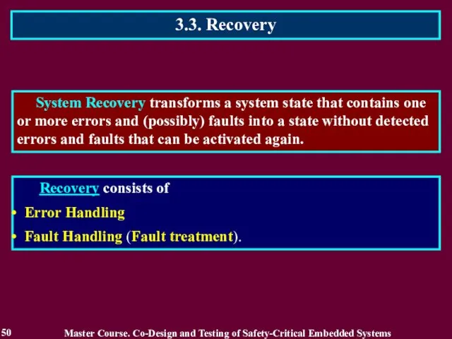
- 50. 3.3. Recovery 50 System Recovery transforms a system state that contains one or more errors and
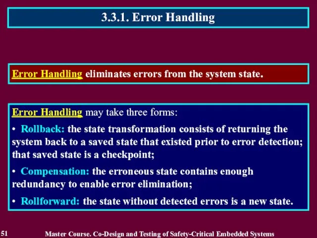
- 51. 3.3.1. Error Handling 51 Error Handling eliminates errors from the system state. Error Handling may take
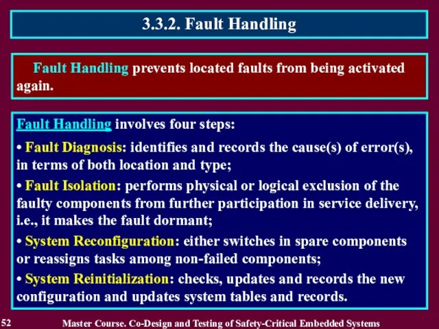
- 52. 3.3.2. Fault Handling 52 Fault Handling prevents located faults from being activated again. Fault Handling involves
- 53. 3.4. Fault-Tolerant Technologies 53 Fault-Tolerant Technologies traditionally used in co-design of S-CES: Use of Detecting and
- 54. 3.4.1 Use of Detecting and Correcting codes 54 Residue check equations: KA + KB = KS
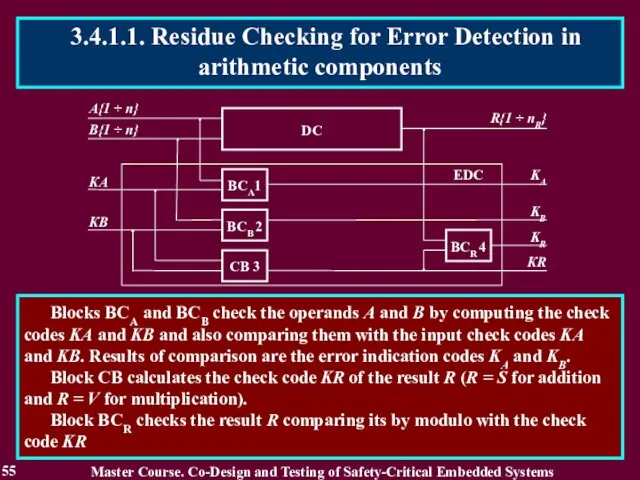
- 55. 55 Blocks BCA and BCB check the operands A and B by computing the check codes
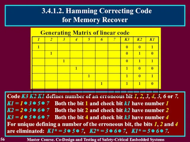
- 56. 56 Code K3 K2 K1 defines number of an erroneous bit 1, 2, 3, 4, 5,
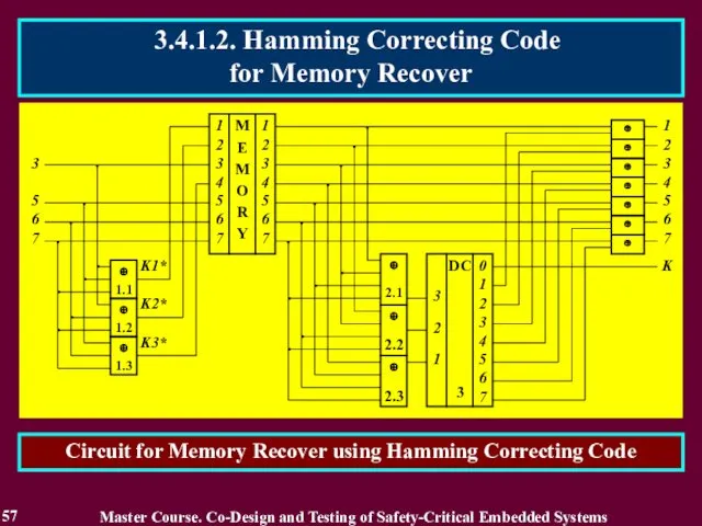
- 57. 57 Circuit for Memory Recover using Hamming Correcting Code Master Course. Co-Design and Testing of Safety-Critical
- 58. Generating Matrix of correcting code for Majority Structures Majority circuit 3.4.2. Majority Structures 58 Majority structure
- 59. Multi-Version System (MVS) contains more than one version for solving a computing task. The version is
- 60. Multi-Version System based on Diversity (Multi-Versity or Version Redundancy). Diversity means a type of redundancy based
- 61. A two-version system W is described by quintuple: W = {X, F, Z, V, U}, where
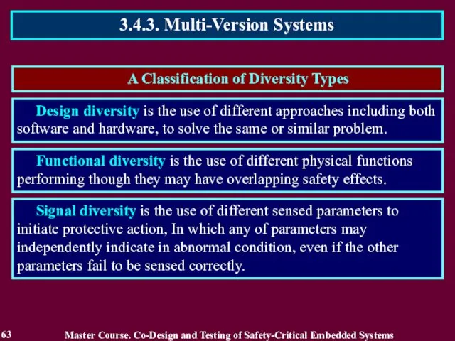
- 62. A Classification of Diversity Types 3.4.3. Multi-Version Systems 62 Master Course. Co-Design and Testing of Safety-Critical
- 63. A Classification of Diversity Types 3.4.3. Multi-Version Systems 63 Master Course. Co-Design and Testing of Safety-Critical
- 64. 3.4.3. Multi-Version Systems 64 Master Course. Co-Design and Testing of Safety-Critical Embedded Systems Diversity types in
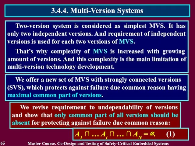
- 65. Two-version system is considered as simplest MVS. It has only two independent versions. And requirement of
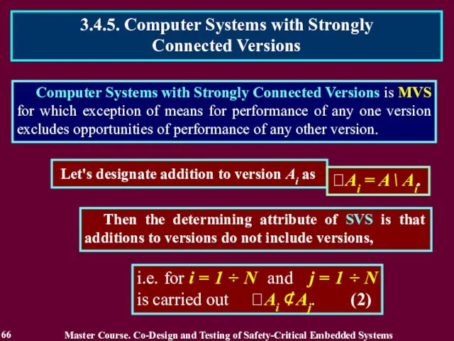
- 66. Computer Systems with Strongly Connected Versions is MVS for which exception of means for performance of
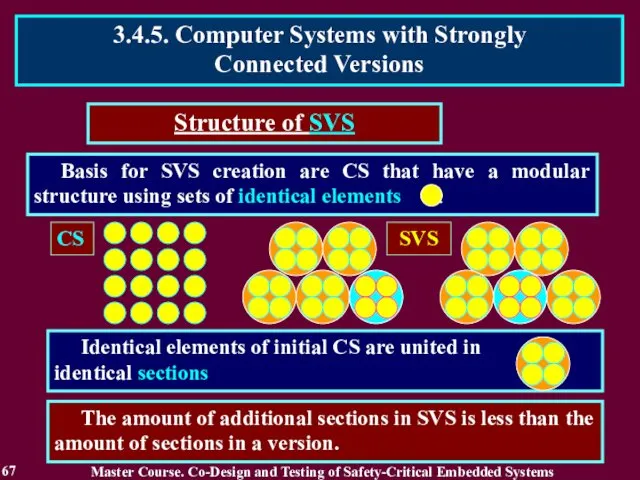
- 67. Basis for SVS creation are CS that have a modular structure using sets of identical elements
- 68. A minimum quantity of versions in a SVS is three A maximum quantity of versions in
- 69. The SVS becomes protected from failure due to the common reason using two components: means of
- 70. Complexity of SVS QIE = R + R / K, QSVS MIN = R (1+1/K) 2,
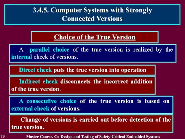
- 71. The SVS can be realized with: Choice of the True Version a consecutive choice of the
- 72. Choice of the true version is executed by the on-line testing methods using means of hardware
- 73. A parallel choice of the true version is realized by the internal check of versions. Direct
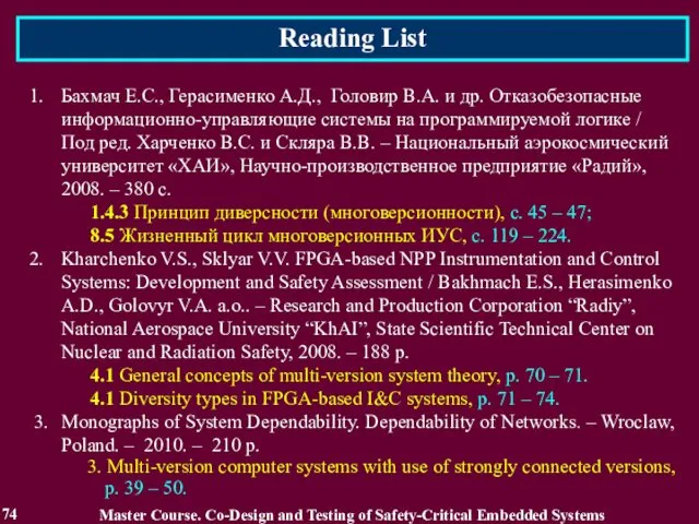
- 74. Reading List 74 Master Course. Co-Design and Testing of Safety-Critical Embedded Systems Бахмач Е.С., Герасименко А.Д.,
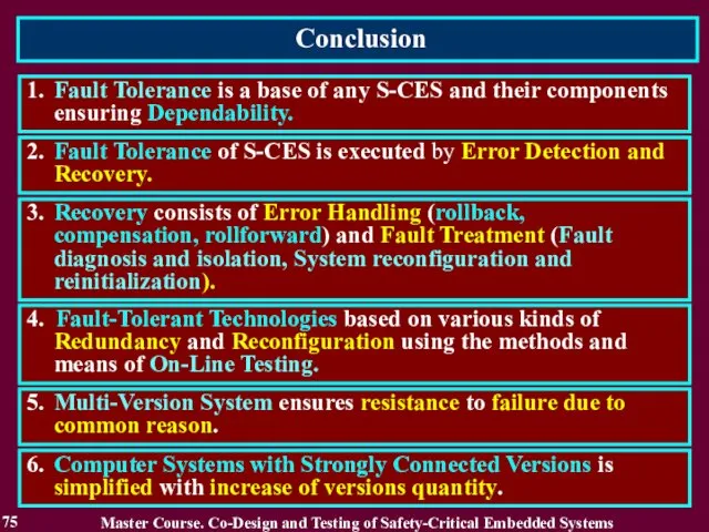
- 75. Conclusion 75 1. Fault Tolerance is a base of any S-CES and their components ensuring Dependability.
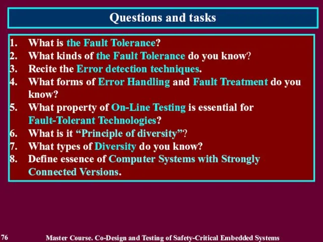
- 76. Questions and tasks 76 What is the Fault Tolerance? What kinds of the Fault Tolerance do
- 77. MODULE 3. On-line testing for digital component of S-CES Master Course. Co-Design and Testing of Safety-Critical
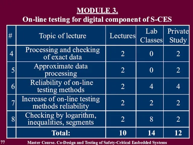
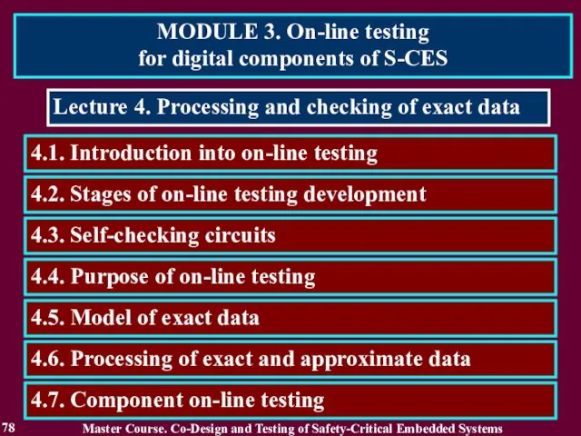
- 78. MODULE 3. On-line testing for digital components of S-CES 78 Lecture 4. Processing and checking of
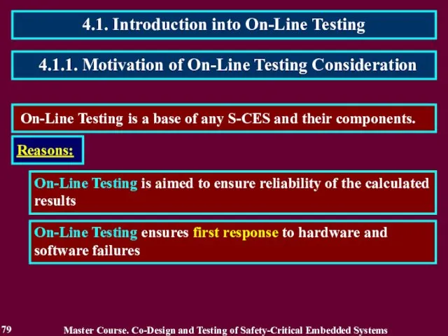
- 79. 4.1. Introduction into On-Line Testing 79 On-Line Testing is a base of any S-CES and their
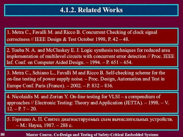
- 80. 4.1.2. Related Works 80 Master Course. Co-Design and Testing of Safety-Critical Embedded Systems 1. Metra C.,
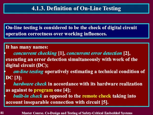
- 81. 4.1.3. Definition of On-Line Testing 81 It has many names: concurrent checking [1], concurrent error detection
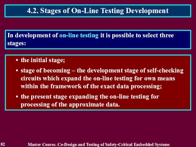
- 82. 4.2. Stages of On-Line Testing Development 82 the initial stage; stage of becoming – the development
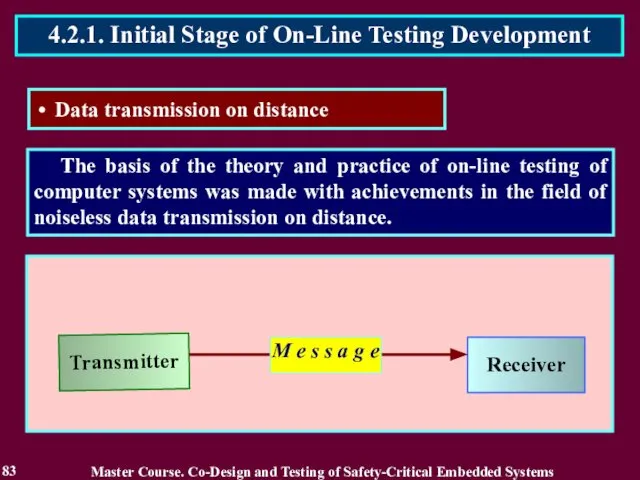
- 83. The basis of the theory and practice of on-line testing of computer systems was made with
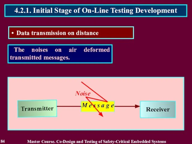
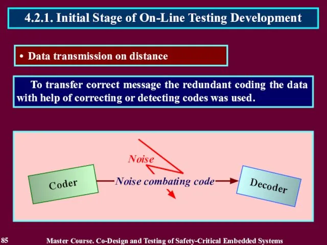
- 84. The noises on air deformed transmitted messages. 84 4.2.1. Initial Stage of On-Line Testing Development Data
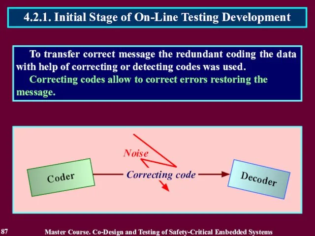
- 85. To transfer correct message the redundant coding the data with help of correcting or detecting codes
- 86. To transfer correct message the redundant coding the data with help of correcting or detecting codes
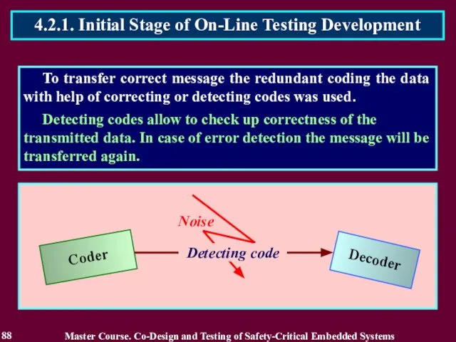
- 87. To transfer correct message the redundant coding the data with help of correcting or detecting codes
- 88. To transfer correct message the redundant coding the data with help of correcting or detecting codes
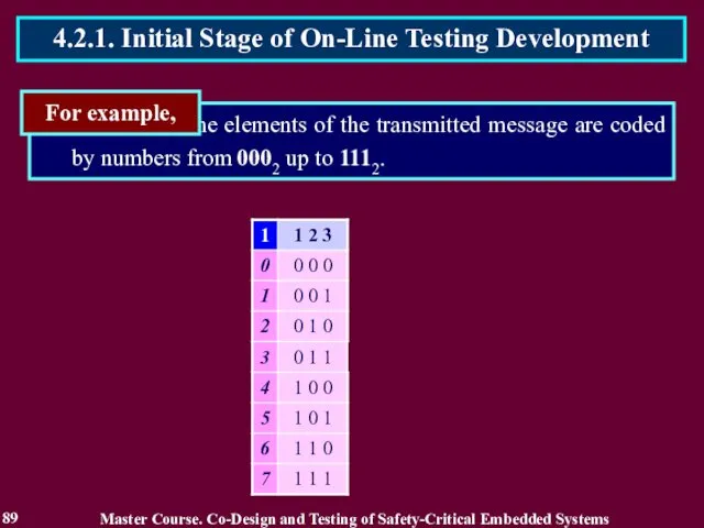
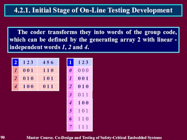
- 89. the elements of the transmitted message are coded by numbers from 0002 up to 1112. For
- 90. The coder transforms they into words of the group code, which can be defined by the
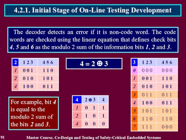
- 91. The decoder detects an error if it is non-code word. The code words are checked using
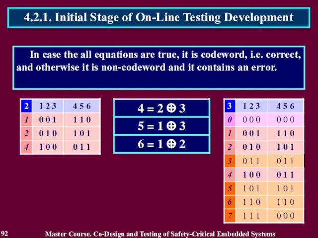
- 92. In case the all equations are true, it is codeword, i.e. correct, and otherwise it is
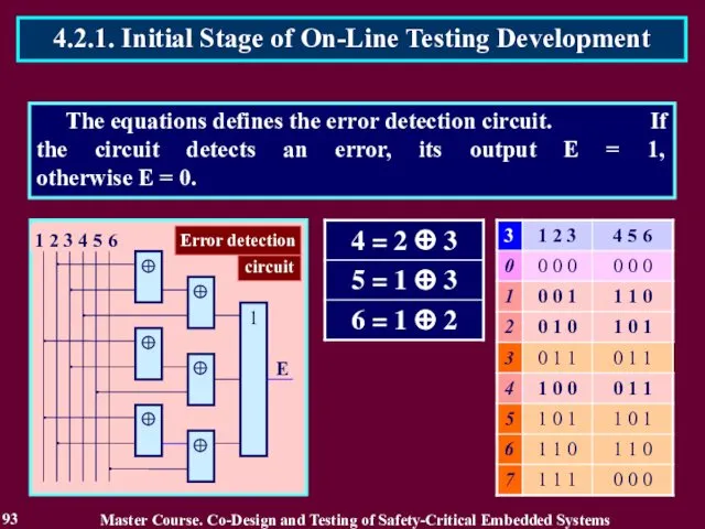
- 93. The equations defines the error detection circuit. If the circuit detects an error, its output E
- 94. Coders and decoders were considered absolutely reliable during message transfer and consequently were checked only by
- 95. In 1968 on the congress in Edinburgh Carter and Schneider for the first time have paid
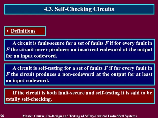
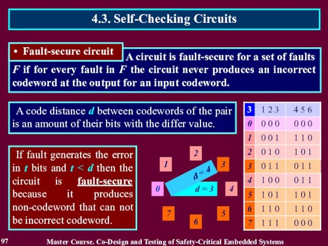
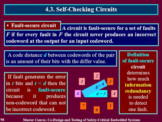
- 96. A circuit is fault-secure for a set of faults F if for every fault in F
- 97. A circuit is fault-secure for a set of faults F if for every fault in F
- 98. A circuit is fault-secure for a set of faults F if for every fault in F
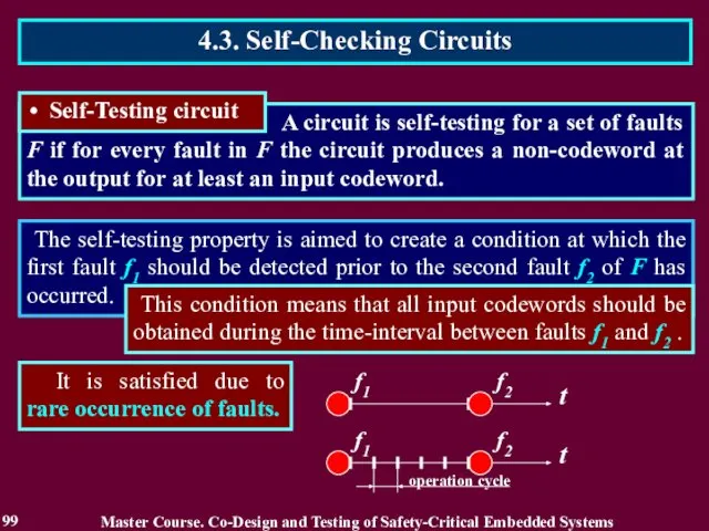
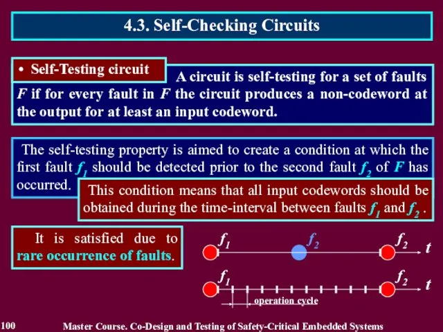
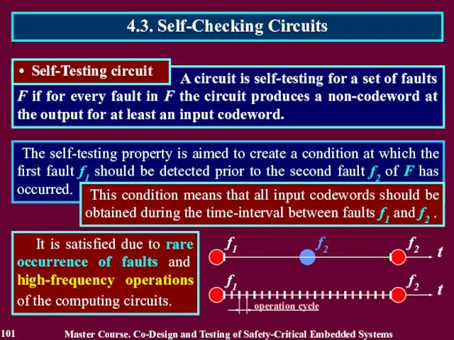
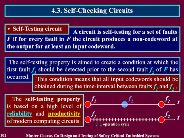
- 99. The self-testing property is aimed to create a condition at which the first fault f1 should
- 100. The self-testing property is aimed to create a condition at which the first fault f1 should
- 101. The self-testing property is aimed to create a condition at which the first fault f1 should
- 102. The self-testing property is aimed to create a condition at which the first fault f1 should
- 103. According to these definitions the designed circuit is not self-checking in a set of stuck-at faults.
- 104. Such circuit is not self-testing and not self-checking in set of the stuck-at faults. Stuck-at «0»
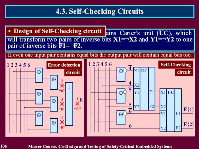
- 105. 4.3. Self-Checking Circuits In order to design self-checking circuit the bits 4, 5 and 6 are
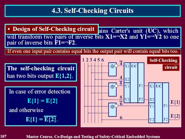
- 106. If even one input pair contains equal bits the output pair will contain equal bits too.
- 107. If even one input pair contains equal bits the output pair will contain equal bits too.
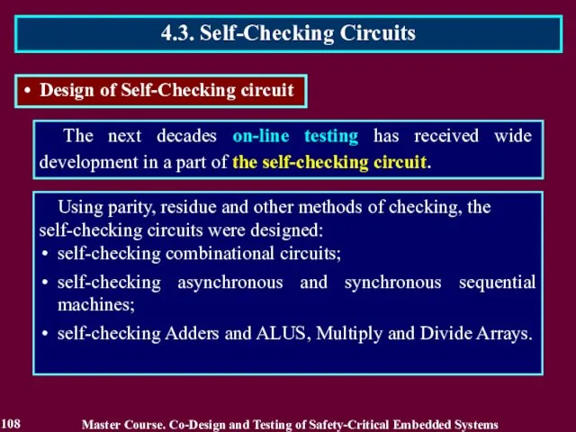
- 108. The next decades on-line testing has received wide development in a part of the self-checking circuit.
- 109. The definitions of self-checking circuit have executed an important role in on-line testing development. There were
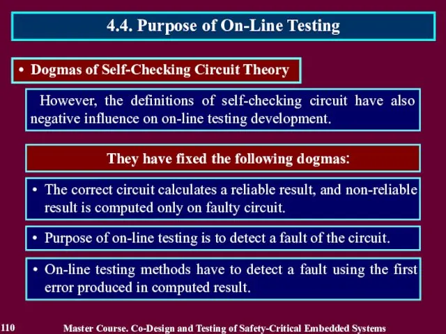
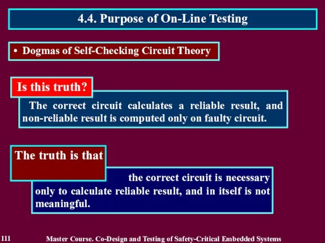
- 110. However, the definitions of self-checking circuit have also negative influence on on-line testing development. They have
- 111. The correct circuit calculates a reliable result, and non-reliable result is computed only on faulty circuit.
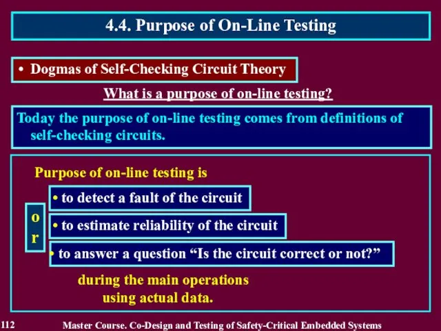
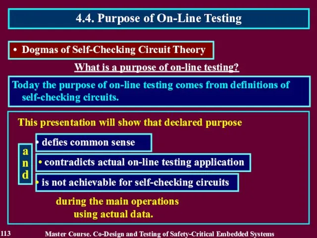
- 112. What is a purpose of on-line testing? Today the purpose of on-line testing comes from definitions
- 113. What is a purpose of on-line testing? Today the purpose of on-line testing comes from definitions
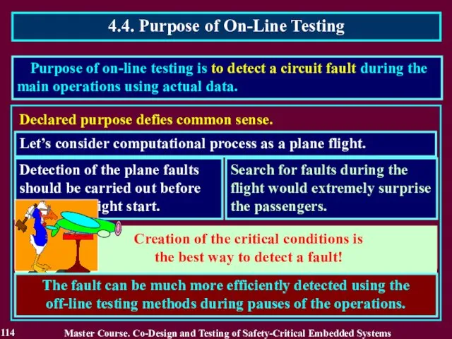
- 114. Creation of the critical conditions is the best way to detect a fault! Purpose of on-line
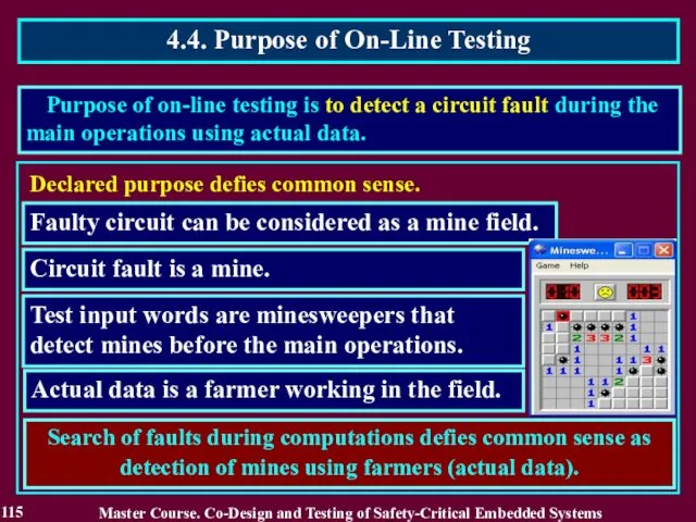
- 115. Search of faults during computations defies common sense as detection of mines using farmers (actual data).
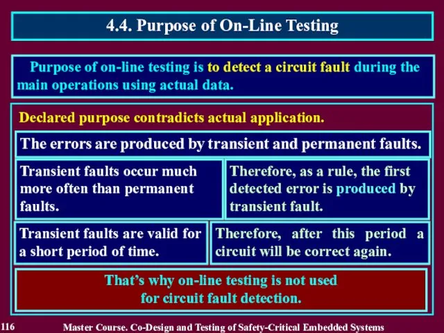
- 116. Declared purpose contradicts actual application. The errors are produced by transient and permanent faults. Transient faults
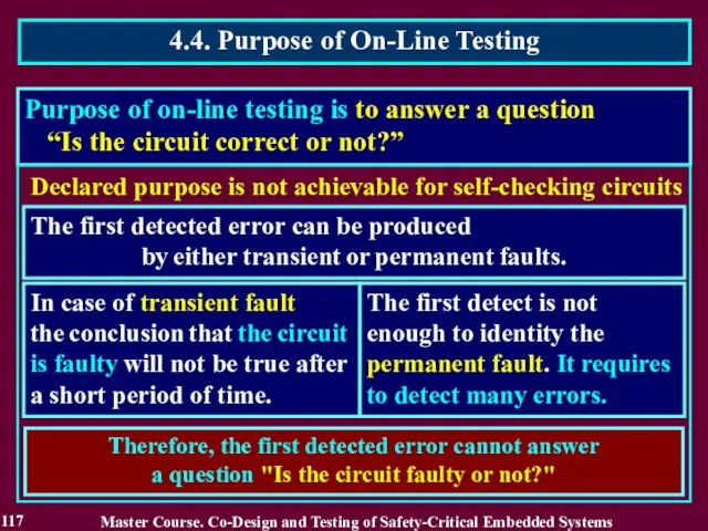
- 117. Purpose of on-line testing is to answer a question “Is the circuit correct or not?” Declared
- 118. Actual purpose of on-line testing is to detect an error, which reduces reliability of the calculated
- 119. Declared purpose Declared vs. Actual purpose Actual purpose is to estimate reliability of a result is
- 120. This model means that all numbers irrespectively of their true nature are considered as exact data.
- 121. The universe of the approximated data The universe outside of an error does not exist, does
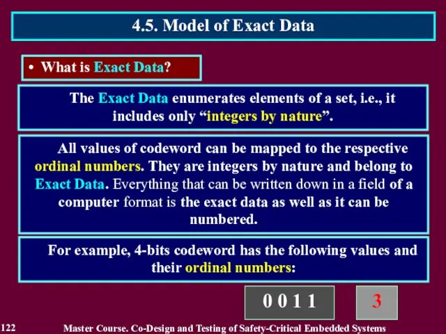
- 122. All values of codeword can be mapped to the respective ordinal numbers. They are integers by
- 123. The exact data model means that all numbers irrespectively of their true nature are considered as
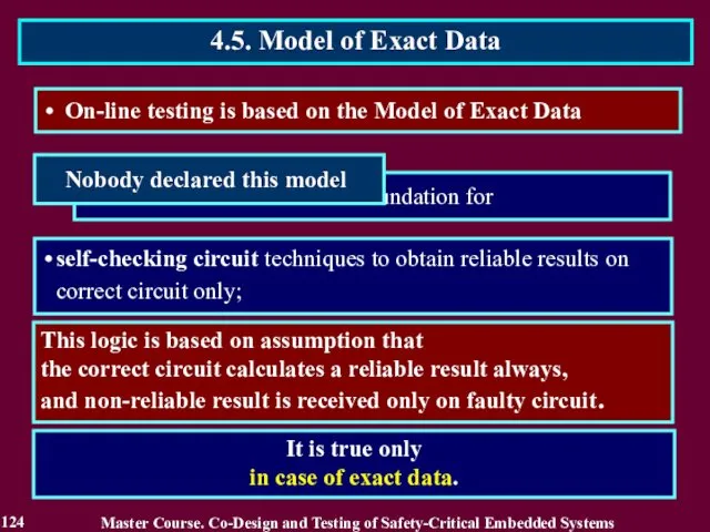
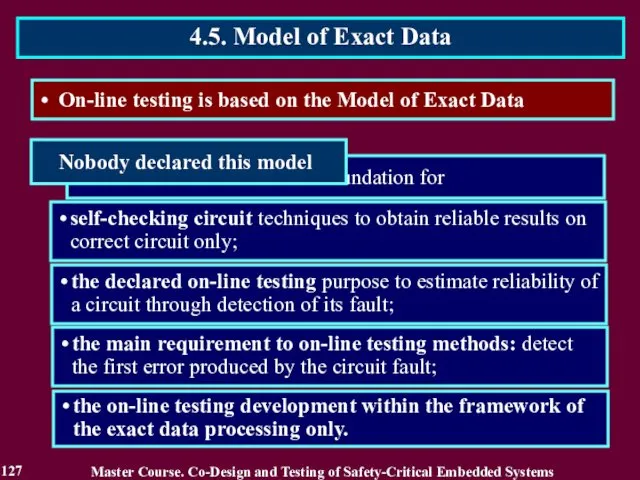
- 124. On-line testing is based on the Model of Exact Data This logic is based on assumption
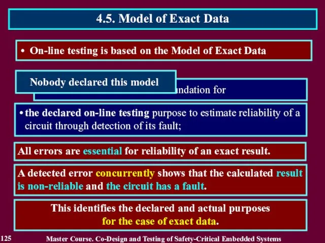
- 125. On-line testing is based on the Model of Exact Data All errors are essential for reliability
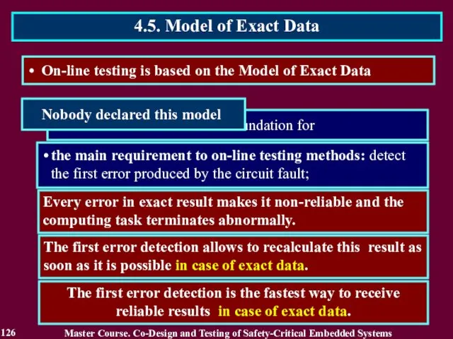
- 126. Every error in exact result makes it non-reliable and the computing task terminates abnormally. The first
- 127. self-checking circuit techniques to obtain reliable results on correct circuit only; the declared on-line testing purpose
- 128. Reading List 128 Master Course. Co-Design and Testing of Safety-Critical Embedded Systems Дрозд А. Этапы развития
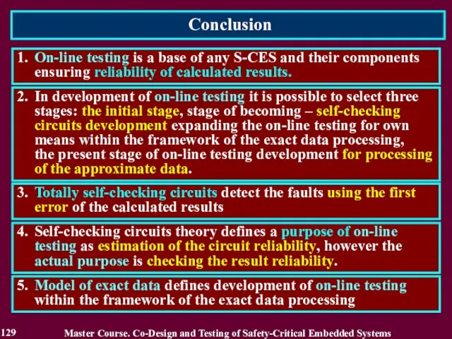
- 129. Conclusion 129 1. On-line testing is a base of any S-CES and their components ensuring reliability
- 130. Questions and tasks 130 What names of on-line testing do you know? Recite the stages of
- 131. MODULE 3. On-line testing for digital components of S-CES Lecture 5. Approximate Data Processing 5.3. Complete
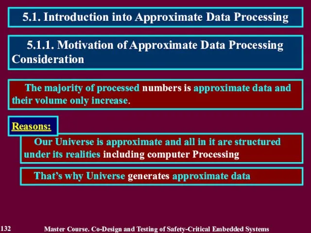
- 132. 5.1. Introduction into Approximate Data Processing The majority of processed numbers is approximate data and their
- 133. 5.1.2. Related Works Master Course. Co-Design and Testing of Safety-Critical Embedded Systems 1. Гук М. Процессоры
- 134. 2. Like special dedicated computing systems. 1. Like reactor-trip systems for nuclear power plants. Sensors Comparators
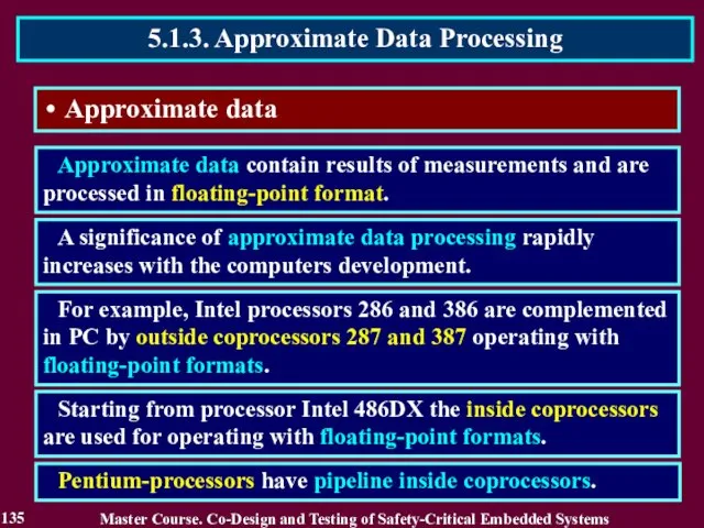
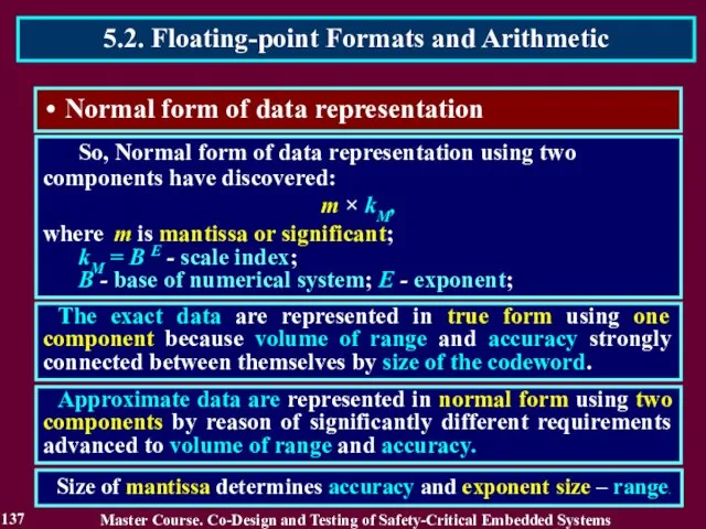
- 135. Approximate data Approximate data contain results of measurements and are processed in floating-point format. A significance
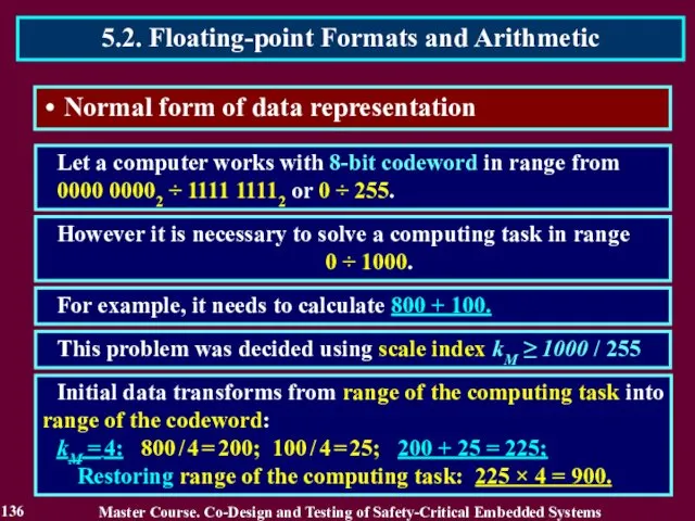
- 136. Normal form of data representation Let a computer works with 8-bit codeword in range from 0000
- 137. Normal form of data representation So, Normal form of data representation using two components have discovered:
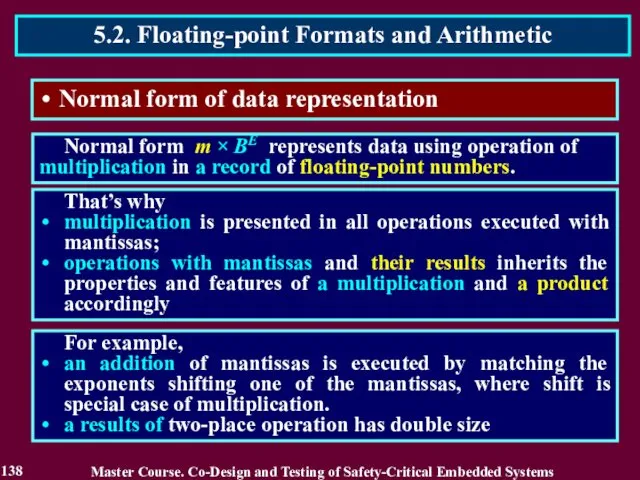
- 138. Normal form of data representation Normal form m × BE represents data using operation of multiplication
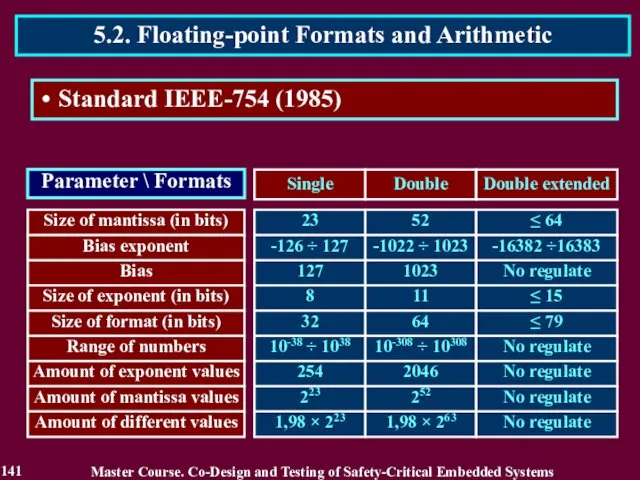
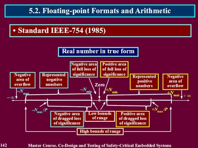
- 139. Extended Formats: Master Course. Co-Design and Testing of Safety-Critical Embedded Systems 5.2. Floating-point Formats and Arithmetic
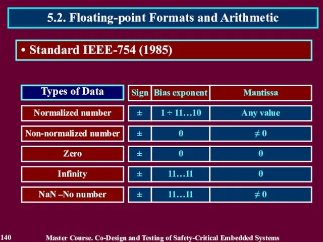
- 140. Master Course. Co-Design and Testing of Safety-Critical Embedded Systems 5.2. Floating-point Formats and Arithmetic 140 Standard
- 141. Master Course. Co-Design and Testing of Safety-Critical Embedded Systems 5.2. Floating-point Formats and Arithmetic 141 Standard
- 142. Master Course. Co-Design and Testing of Safety-Critical Embedded Systems 5.2. Floating-point Formats and Arithmetic 142 Standard
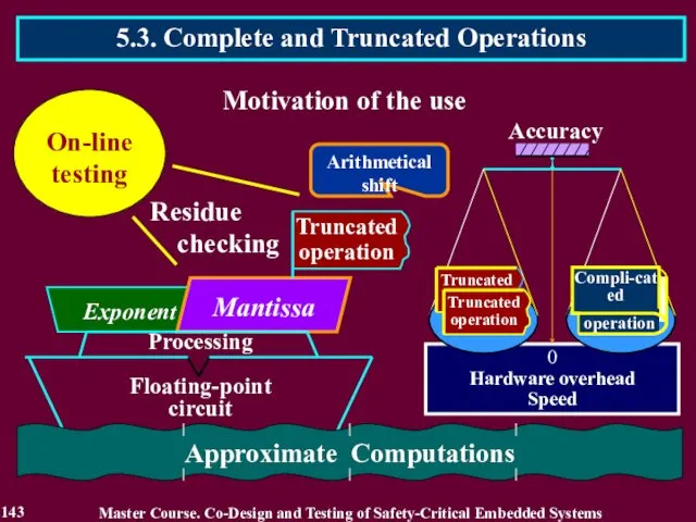
- 143. 5.3. Complete and Truncated Operations 143 Master Course. Co-Design and Testing of Safety-Critical Embedded Systems
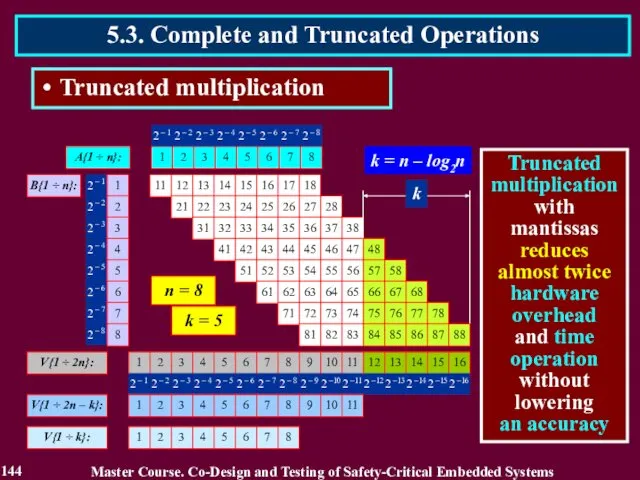
- 144. 5.3. Complete and Truncated Operations Truncated multiplication 144 Master Course. Co-Design and Testing of Safety-Critical Embedded
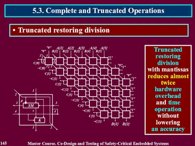
- 145. Master Course. Co-Design and Testing of Safety-Critical Embedded Systems 5.3. Complete and Truncated Operations 145 Truncated
- 146. Master Course. Co-Design and Testing of Safety-Critical Embedded Systems 5.3. Complete and Truncated Operations 146 Truncated
- 147. Master Course. Co-Design and Testing of Safety-Critical Embedded Systems 5.3. Complete and Truncated Operations 147 Truncated
- 148. Deleting of low bits of the calculated result An approximate number A is represented as a
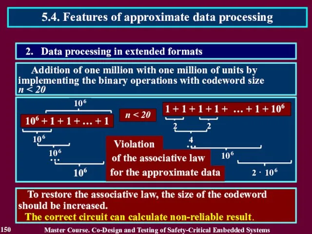
- 149. Addition of one million with one million of units by implementing the binary operations with codeword
- 150. To restore the associative law, the size of the codeword should be increased. The correct circuit
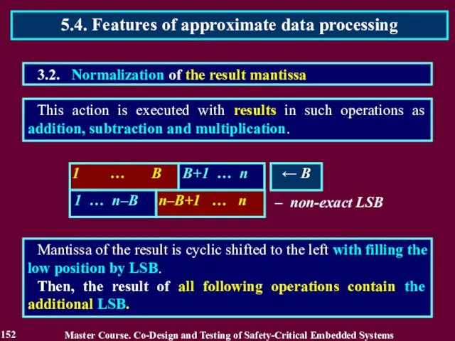
- 151. This action is frequently executed in such operations as addition, subtraction and matching operands. Mantissa of
- 152. This action is executed with results in such operations as addition, subtraction and multiplication. Mantissa of
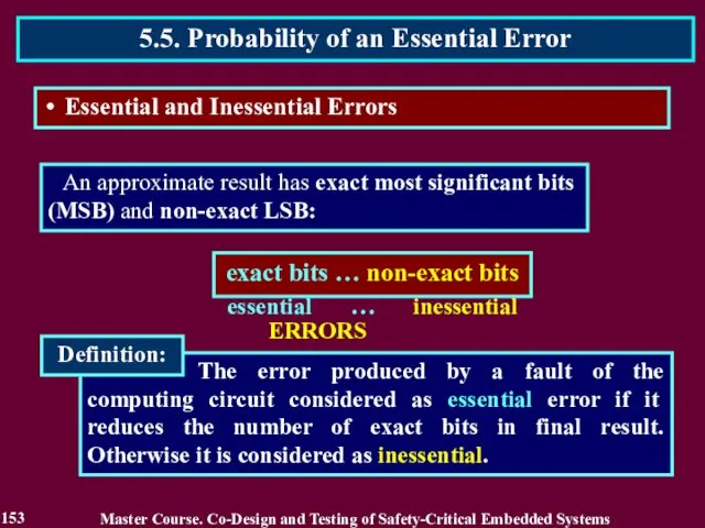
- 153. The error produced by a fault of the computing circuit considered as essential error if it
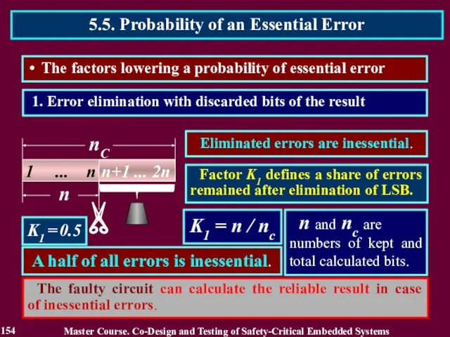
- 154. 1. Error elimination with discarded bits of the result K1 = n / nс K1 =
- 155. K2 = nE / n nE and n are the number of exact bits and total
- 156. OS and OC are the hardware overhead of computing circuits preceding a shifter and total number
- 157. 1 ... n-d 1 ... n-d OS and OC are the hardware overhead of computing circuits
- 158. Probability that the occurred error is essential PE = K1 K2 K3 PE For approximate data
- 159. Reading List 159 Master Course. Co-Design and Testing of Safety-Critical Embedded Systems Полин Е. Л. Арифметика
- 160. Conclusion 160 1. The majority of processed numbers is approximate data and their volume only increase.
- 161. Questions and tasks 161 What role do the approximate data play in computer processing? What kind
- 162. MODULE 3. On-line testing for digital components of S-CES Lecture 6. Reliability of on-line testing methods
- 163. 6.1. Reliability of traditional on-line testing methods Estimation in reliability of traditional on-line testing methods should
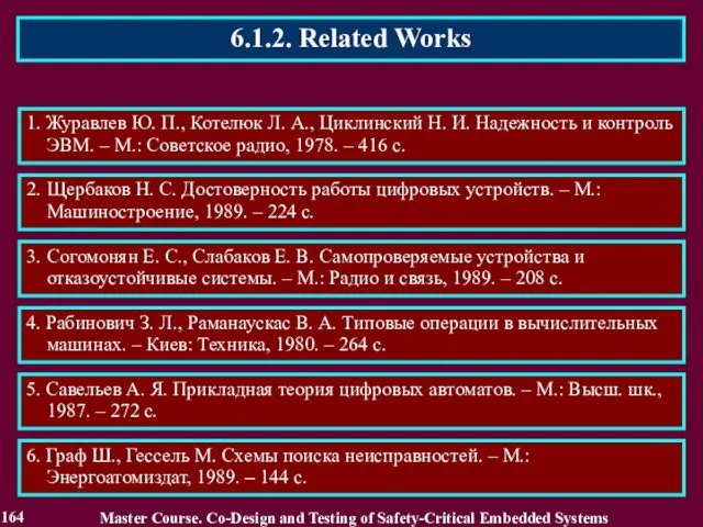
- 164. 6.1.2. Related Works Master Course. Co-Design and Testing of Safety-Critical Embedded Systems 1. Журавлев Ю. П.,
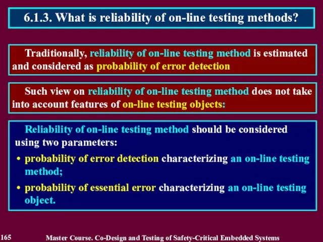
- 165. Traditionally, reliability of on-line testing method is estimated and considered as probability of error detection 6.1.3.
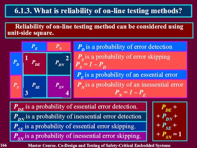
- 166. Reliability of on-line testing method can be considered using unit-side square. 6.1.3. What is reliability of
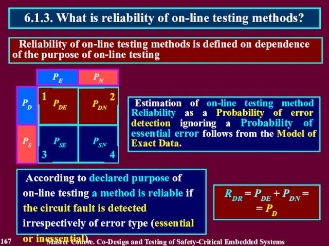
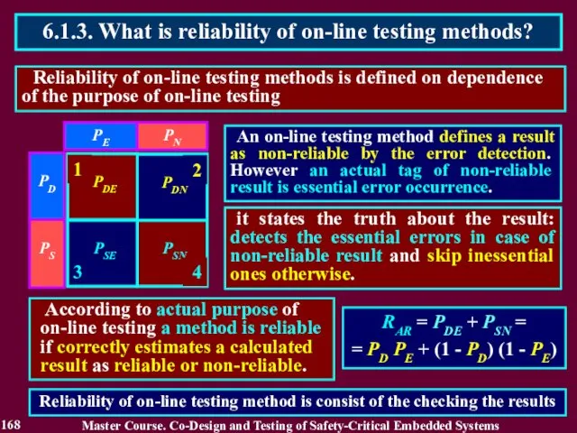
- 167. Reliability of on-line testing methods is defined on dependence of the purpose of on-line testing 6.1.3.
- 168. Reliability of on-line testing methods is defined on dependence of the purpose of on-line testing 6.1.3.
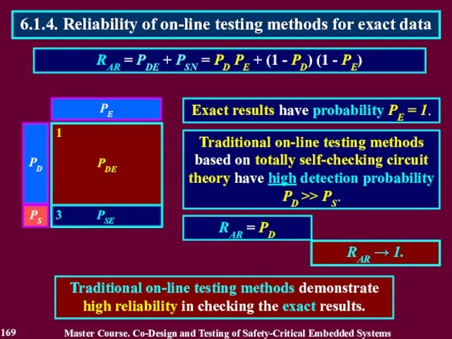
- 169. Traditional on-line testing methods based on totally self-checking circuit theory have high detection probability PD >>
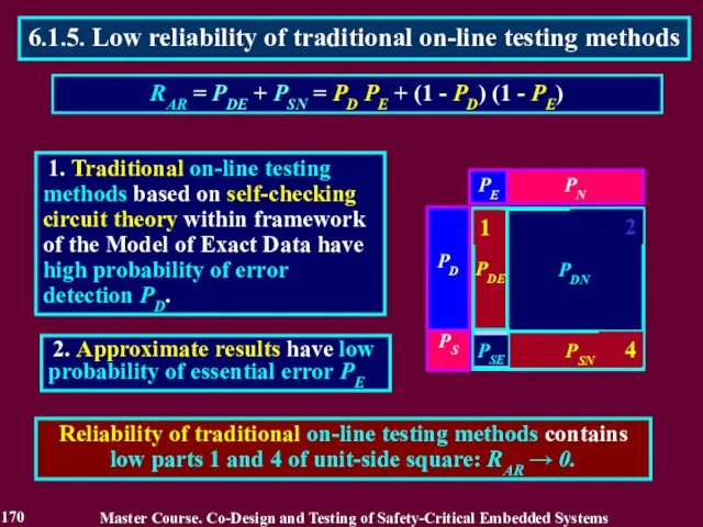
- 170. 1. Traditional on-line testing methods based on self-checking circuit theory within framework of the Model of
- 171. 3. The part 2 demonstrates a new property of an on-line testing method to eject reliable
- 172. CURRENT VIEW Existing on-line testing is applicable to any type of data. A purpose of on-line
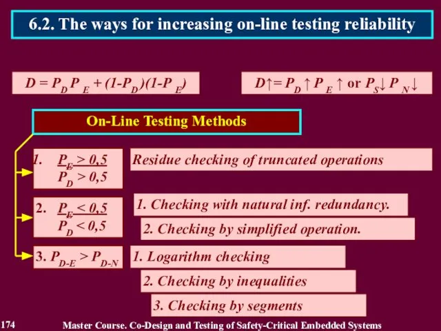
- 173. 1. РE > 0,5 D = РD Р E + (1-РD )(1-Р E) D↑= РD ↑
- 174. D = РD Р E + (1-РD )(1-Р E) D↑= РD ↑ Р E ↑ or
- 175. D↑= РD ↑ Р E ↑ (РE > 0,5) & (РD > 0,5) 1. The first
- 176. 176 Master Course. Co-Design and Testing of Safety-Critical Embedded Systems 6.3. The first way for increasing
- 177. V{1 ÷ 2n}: n = 14 k = 10 V1 V2 V3 V6 V8 V9 V10
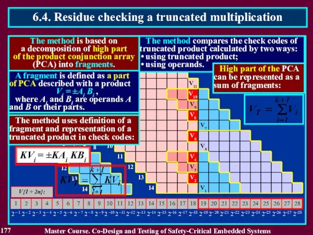
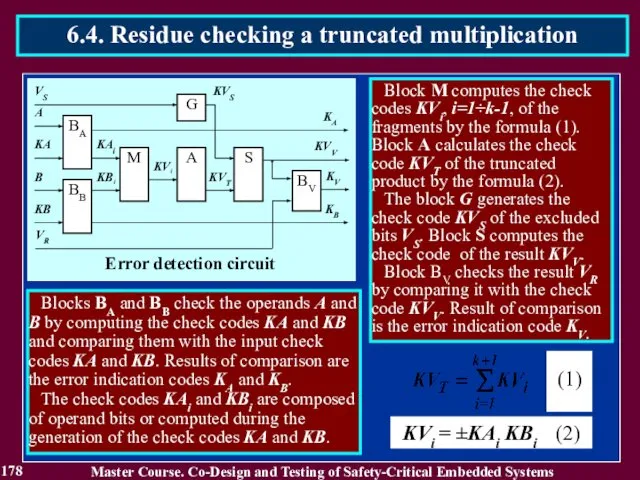
- 178. 178 Master Course. Co-Design and Testing of Safety-Critical Embedded Systems 6.4. Residue checking a truncated multiplication
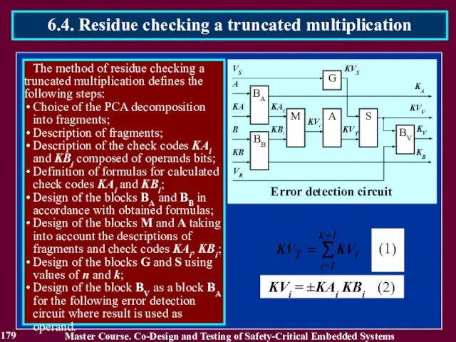
- 179. 179 Master Course. Co-Design and Testing of Safety-Critical Embedded Systems 6.4. Residue checking a truncated multiplication
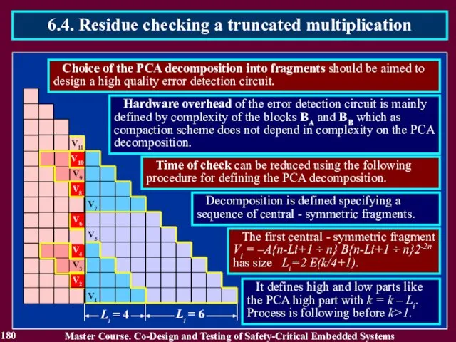
- 180. 180 Master Course. Co-Design and Testing of Safety-Critical Embedded Systems 6.4. Residue checking a truncated multiplication
- 181. 181 Master Course. Co-Design and Testing of Safety-Critical Embedded Systems 6.4. Residue checking a truncated multiplication
- 182. 182 Master Course. Co-Design and Testing of Safety-Critical Embedded Systems 6.4. Residue checking a truncated multiplication
- 183. 183 Master Course. Co-Design and Testing of Safety-Critical Embedded Systems 6.4. Residue checking a truncated multiplication
- 184. 184 Master Course. Co-Design and Testing of Safety-Critical Embedded Systems 6.5. Residue checking a truncated division
- 185. 185 Master Course. Co-Design and Testing of Safety-Critical Embedded Systems 6.5. Residue checking a truncated division
- 186. 186 Master Course. Co-Design and Testing of Safety-Critical Embedded Systems 6.5. Residue checking a truncated division
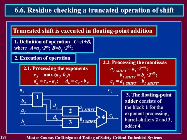
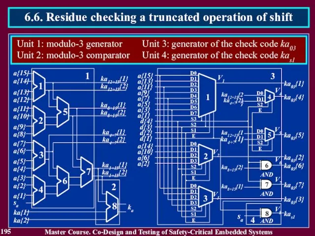
- 187. 187 Master Course. Co-Design and Testing of Safety-Critical Embedded Systems 6.6. Residue checking a truncated operation
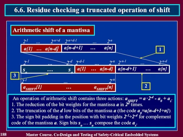
- 188. 188 Master Course. Co-Design and Testing of Safety-Critical Embedded Systems 6.6. Residue checking a truncated operation
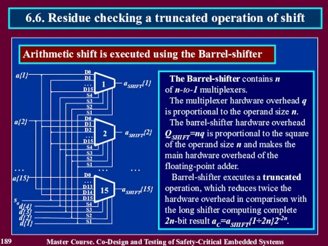
- 189. 189 Master Course. Co-Design and Testing of Safety-Critical Embedded Systems 6.6. Residue checking a truncated operation
- 190. 190 Master Course. Co-Design and Testing of Safety-Critical Embedded Systems 6.6. Residue checking a truncated operation
- 191. 191 Master Course. Co-Design and Testing of Safety-Critical Embedded Systems 6.6. Residue checking a truncated operation
- 192. 192 Master Course. Co-Design and Testing of Safety-Critical Embedded Systems 6.6. Residue checking a truncated operation
- 193. 193 Master Course. Co-Design and Testing of Safety-Critical Embedded Systems 6.6. Residue checking a truncated operation
- 194. 194 Master Course. Co-Design and Testing of Safety-Critical Embedded Systems 6.6. Residue checking a truncated operation
- 195. 195 Master Course. Co-Design and Testing of Safety-Critical Embedded Systems 6.6. Residue checking a truncated operation
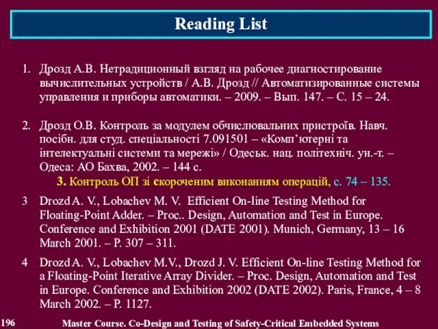
- 196. Reading List 196 Master Course. Co-Design and Testing of Safety-Critical Embedded Systems 1. Дрозд А.В. Нетрадиционный
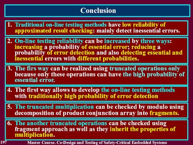
- 197. Conclusion 197 1. Traditional on-line testing methods have low reliability of approximated result checking: mainly detect
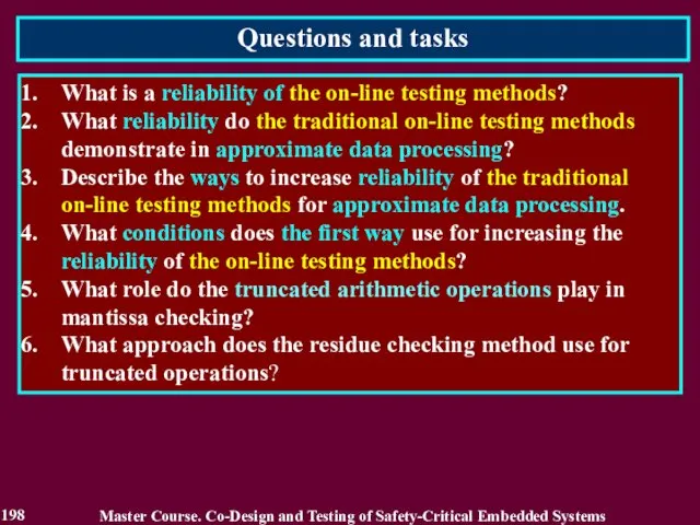
- 198. Questions and tasks 198 What is a reliability of the on-line testing methods? What reliability do
- 199. MODULE 3. On-line testing for digital components of S-CES Lecture 7. Increase of on-line testing methods
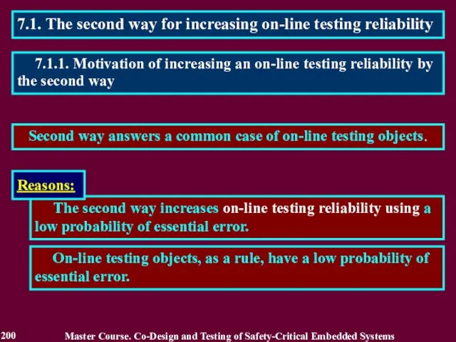
- 200. 7.1. The second way for increasing on-line testing reliability Second way answers a common case of
- 201. 7.1.2. Related Works Master Course. Co-Design and Testing of Safety-Critical Embedded Systems 1. Савченко Ю. Г.
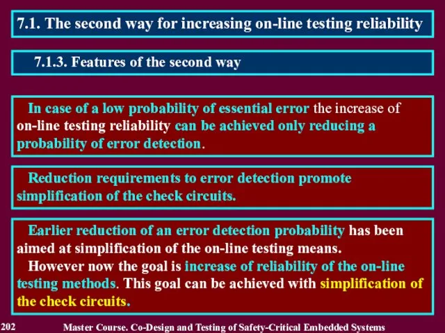
- 202. 7.1. The second way for increasing on-line testing reliability In case of a low probability of
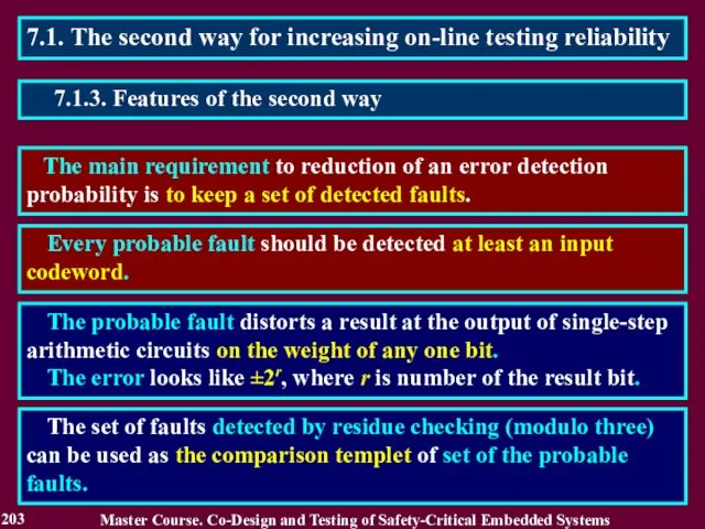
- 203. 7.1. The second way for increasing on-line testing reliability The main requirement to reduction of an
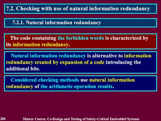
- 204. 7.2. Checking with use of natural information redundancy The code containing the forbidden words is characterized
- 205. 7.3. The use of product information redundancy Really the product contains the forbidden words. This follows
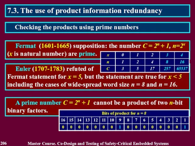
- 206. 7.3. The use of product information redundancy Fermat (1601-1665) supposition: the number C = 2n +
- 207. 7.3. The use of product information redundancy A prime number С = 2n+1 and numbers which
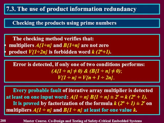
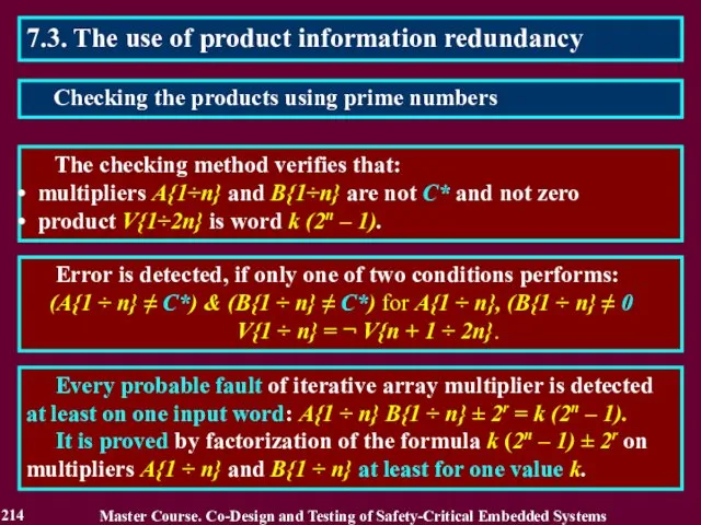
- 208. 7.3. The use of product information redundancy The checking method verifies that: multipliers A{1÷n} and B{1÷n}
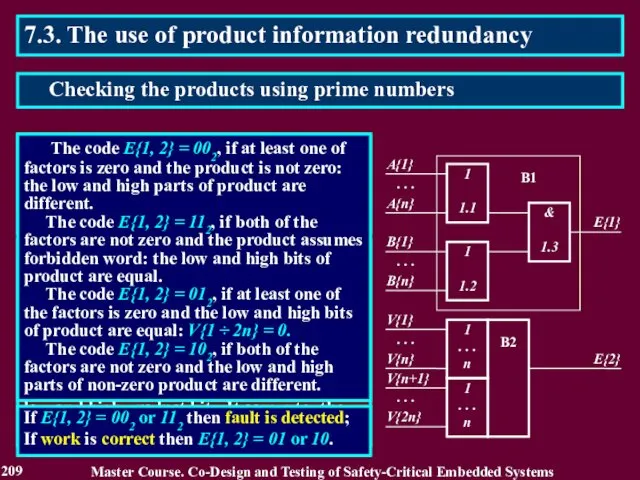
- 209. 7.3. The use of product information redundancy The checker consists of two blocks and forms two-bits
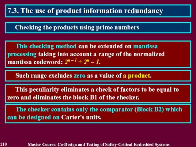
- 210. 7.3. The use of product information redundancy This checking method can be extended on mantissa processing
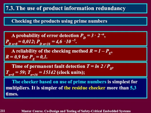
- 211. 7.3. The use of product information redundancy A probability of error detection PD = 3⋅ 2
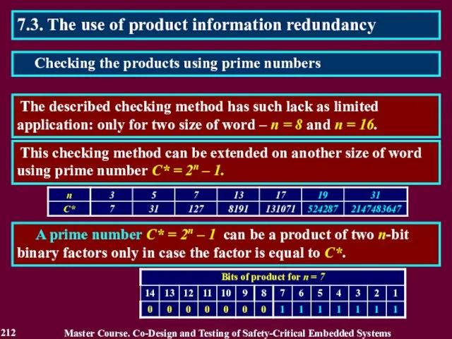
- 212. 7.3. The use of product information redundancy The described checking method has such lack as limited
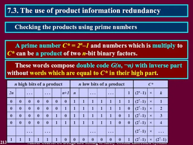
- 213. 7.3. The use of product information redundancy A prime number С* = 2n–1 and numbers which
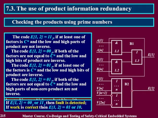
- 214. 7.3. The use of product information redundancy The checking method verifies that: multipliers A{1÷n} and B{1÷n}
- 215. 7.3. The use of product information redundancy The checker consists of two blocks and forms two-bits
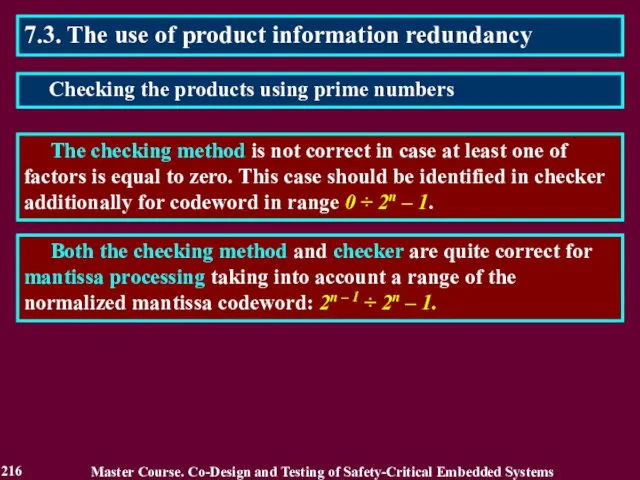
- 216. 7.3. The use of product information redundancy The checking method is not correct in case at
- 217. 7.3. The use of product information redundancy A probability of error detection PD = 3⋅ 2
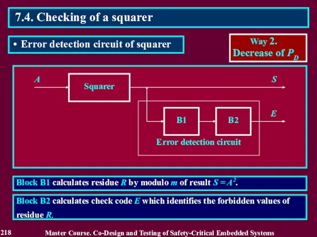
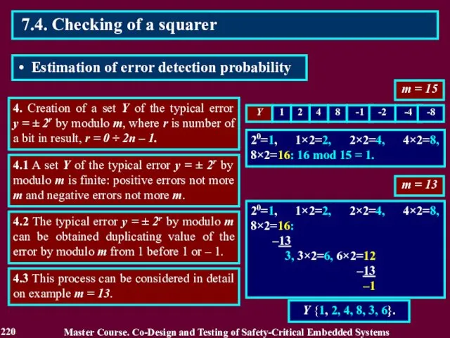
- 218. Block B1 calculates residue R by modulo m of result S = A2. A Squarer B1
- 219. 1. Calculation of square S = A2 and residue R = S mod m for values
- 220. m = 15 4. Creation of a set Y of the typical error y = ±
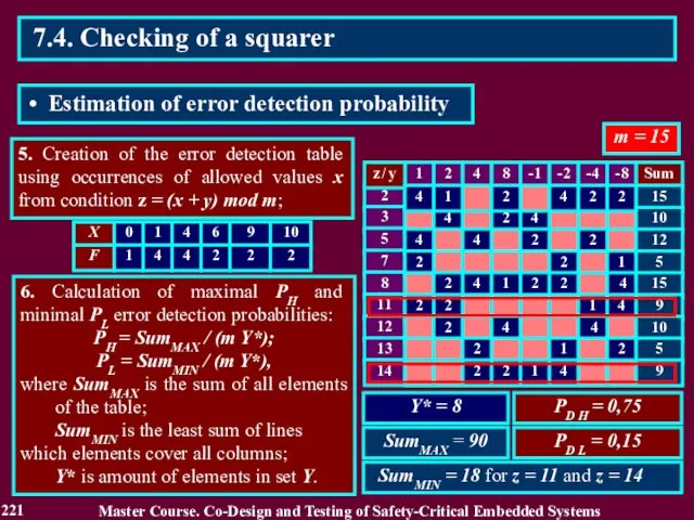
- 221. 5. Creation of the error detection table using occurrences of allowed values x from condition z
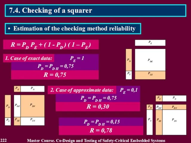
- 222. R = PD PE + ( 1 - PD ) ( 1 – PE ) 222
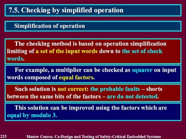
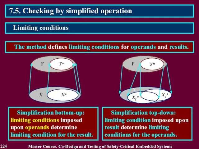
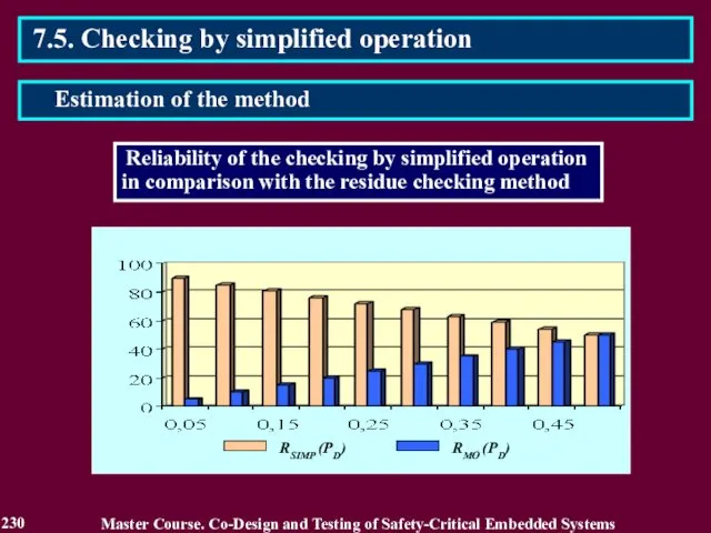
- 223. 7.5. Checking by simplified operation The checking method is based on operation simplification limiting of a
- 224. 7.5. Checking by simplified operation The method defines limiting conditions for operands and results. Master Course.
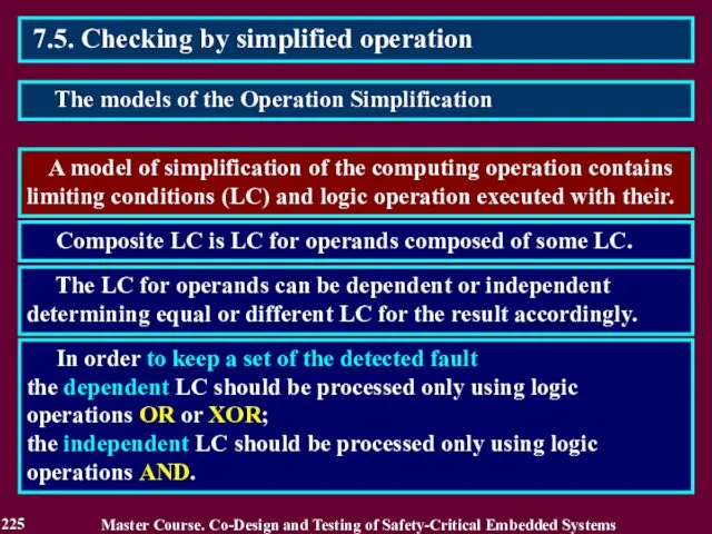
- 225. 7.5. Checking by simplified operation A model of simplification of the computing operation contains limiting conditions
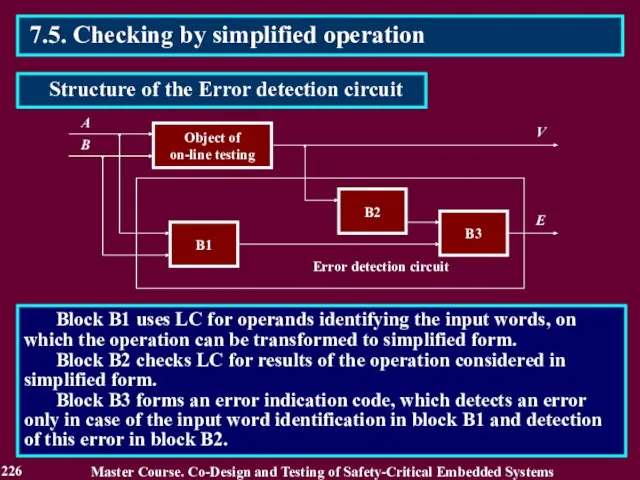
- 226. Block B1 uses LC for operands identifying the input words, on which the operation can be
- 227. 7.5. Checking by simplified operation Two kinds of the check calculations are used: forming the codes
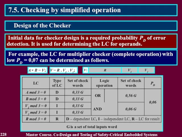
- 228. 7.5. Checking by simplified operation Initial data for checker design is a required probability PD of
- 229. 7.5. Checking by simplified operation Master Course. Co-Design and Testing of Safety-Critical Embedded Systems Design of
- 230. 7.5. Checking by simplified operation Master Course. Co-Design and Testing of Safety-Critical Embedded Systems Estimation of
- 231. Reading List 231 Master Course. Co-Design and Testing of Safety-Critical Embedded Systems 1. Drozd A. V.
- 232. Conclusion 232 1. The second way can be realized using natural information redundancy of results of
- 233. Questions and tasks 233 What is the second method for increasing a reliability of the on-line
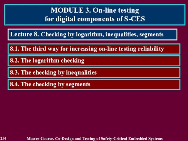
- 234. MODULE 3. On-line testing for digital components of S-CES Lecture 8. Checking by logarithm, inequalities, segments
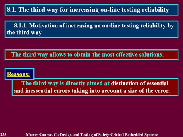
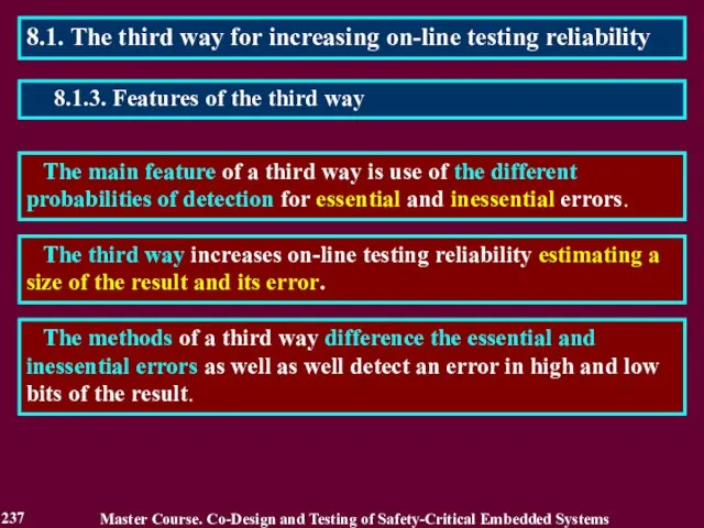
- 235. 8.1. The third way for increasing on-line testing reliability The third way allows to obtain the
- 236. 8.1.2. Related Works Master Course. Co-Design and Testing of Safety-Critical Embedded Systems 1. Селлерс Ф. Методы
- 237. 8.1. The third way for increasing on-line testing reliability The main feature of a third way
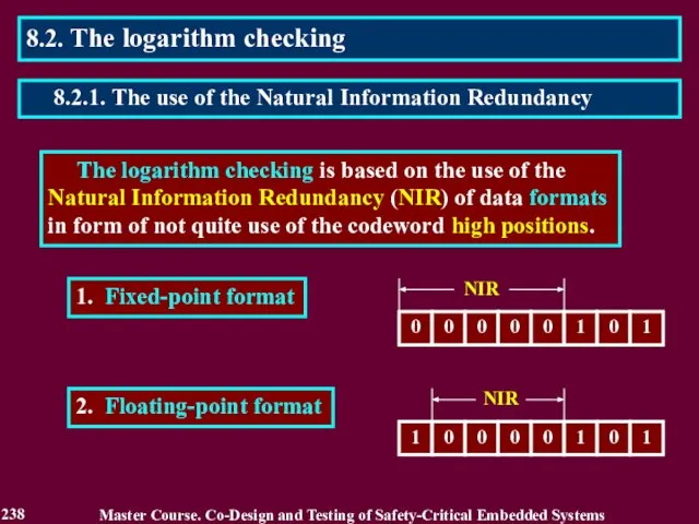
- 238. The logarithm checking is based on the use of the Natural Information Redundancy (NIR) of data
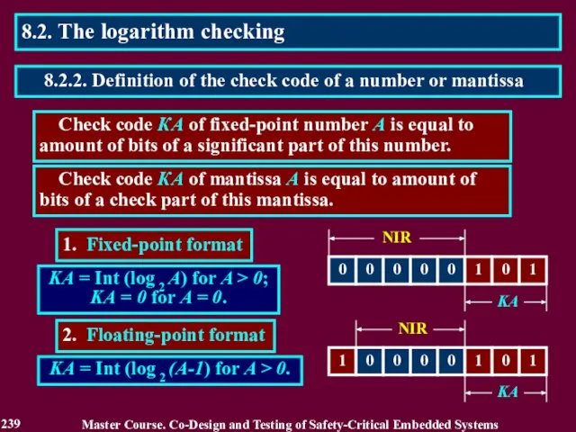
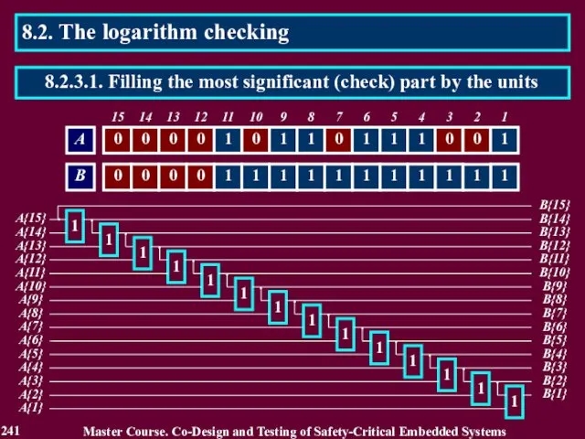
- 239. Check code КА of fixed-point number A is equal to amount of bits of a significant
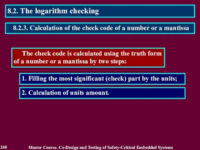
- 240. The check code is calculated using the truth form of a number or a mantissa by
- 241. B{2} 1 A{2} 8.2. The logarithm checking Master Course. Co-Design and Testing of Safety-Critical Embedded Systems
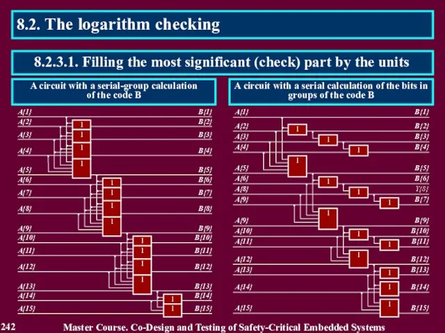
- 242. 8.2. The logarithm checking Master Course. Co-Design and Testing of Safety-Critical Embedded Systems 242 8.2.3.1. Filling
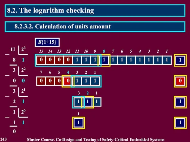
- 243. 8.2. The logarithm checking Master Course. Co-Design and Testing of Safety-Critical Embedded Systems 243 8.2.3.2. Calculation
- 244. The check codes of operands allow predict the check code of arithmetic operation result with difference
- 245. ∙ For addition S = A + B, A ≥ 0 and B ≥ 0: KS
- 246. ∙ For addition S = A + B: KS = KS* + α, where KS* =
- 247. ∙ For multiplication: P = A B, A > 0 and B > 0, KP =
- 248. ∙ For multiplication: P = A ⋅ B, A ≥ 0 and B ≥ 0, KP
- 249. 2 KA – 1 ≤ A Master Course. Co-Design and Testing of Safety-Critical Embedded Systems 249
- 250. Master Course. Co-Design and Testing of Safety-Critical Embedded Systems 250 8.2. The logarithm checking 8.2.4. The
- 251. 1, 2, 3 – formers of check codes V – unit of check codes rename 4
- 252. 1. The error 0 → 1 in the bit γ γ 2. The error 1 →
- 253. 1. The error 0 → 1 in the bit γ is detected with PD = 2
- 254. A method of the checking by inequalities includes: 2. Comparison of the result with its high
- 255. 9/16 Y X YH YL Y = x2 0.5 ≤ x YH = 3/2 x -
- 256. ΔYH = YH - Y 1/16 1/16 ΔYH а = 3/2 x - 1/2 - x2,
- 257. 8.3. Checking by inequalities Master Course. Co-Design and Testing of Safety-Critical Embedded Systems 257 8.3.2. Error
- 258. Master Course. Co-Design and Testing of Safety-Critical Embedded Systems 258 8.4. The checking by segments The
- 259. Examples of the PSCT components 1. Time during which the result remains reliable despite of action
- 260. Estimation of reliability in checking the result D = РDE + РSN without consideration of PSCT
- 261. 1. Division of a result on segments of the bits 2. Serial checking the segments 3.
- 262. PD = 1 / n hN = nE / nN hD = PDE / PDN ,
- 263. The block BO connects inputs of the circuit elements, which calculate the selected segments, to blocks
- 264. Array P of bits Pi j in binary codes of probabilities Pi Sequences of segment checks
- 265. Reliability of the checking the result in a segment i: Di = Pi PE + (1
- 266. Reading List 266 Master Course. Co-Design and Testing of Safety-Critical Embedded Systems 1. Дрозд А. В.
- 267. Conclusion 267 1. The third way is directly aimed at distinction of essential and inessential errors
- 268. Questions and tasks 268 What feature of the third way for increasing a reliability of the
- 269. MODULE 4. Checkability of S-CES digital components Master Course. Co-Design and Testing of Safety-Critical Embedded Systems
- 270. MODULE 4. Checkability of S-CES digital components Lecture 9. Checkability of S-CES digital components: a problem,
- 271. 9.1. Introduction into checkability Master Course. Co-Design and Testing of Safety-Critical Embedded Systems 9.1.1. Motivation of
- 272. 9.1.2. Related Works Master Course. Co-Design and Testing of Safety-Critical Embedded Systems 1. Yastrebenetsky M.A. (edit.).
- 273. 1. Two main operational modes, i.e. normal and emergency ones of S-CES and heir components. For
- 274. Both in the normal and emergency modes, the S-CES components operate with different sets of input
- 275. It is correct for the digital components operating in a single i.e. only normal mode. 9.1.5.
- 276. M(SN, SC, S), where: SN is a component description characterizing its functioning in the normal mode
- 277. Description D of the digital circuit should be illustrated by the specific elements. For instance, the
- 278. 9.2.2. Controllable points of the digital component 1. An internal point of the digital circuit is
- 279. 9.2.3. Observable points of the digital component: 1. A point of the digital circuit is a
- 280. 9.2.4. Properties of the controllable and observable points 9.2. The model of a digital component in
- 281. 9.2.5. Controllability and observability of the points Controllability C can accept 3 values: 0, 1, 2
- 282. 9.2. The model of a digital component in view of the on-line testing for S-CES M(CN,
- 283. 9.3.1. The dangerous points of the S-CES digital components possibility of the latent fault occurrence in
- 284. 9.3.2. Possibilities of the latent fault accumulation in a normal mode The point is a non-controllable
- 285. The point is an observable and non-controllable and its value as a value of the non-controllable
- 286. The external point is dangerous to an emergency mode under the following condition: ((CN + CE
- 287. 9.3.5. Checkability of a digital component Checkability of a digital component can be appreciated by the
- 288. 9.4.1. Research of the digital component checkability 9.4. The ways to increase a checkability of S-CES
- 289. 9.4.1. Research of the digital component checkability 9.4. The ways to increase a checkability of S-CES
- 290. 9.4.1. Research of the digital component checkability 9.4. The ways to increase a checkability of S-CES
- 291. Particularities of the S-CES digital components: 1. High level of the input data consistency in a
- 292. Particularities of the S-CES digital components: 9.4.2. Reasons of low checkability of the S-CES digital components
- 293. 1. Change of input data alternating a normal mode with a simulated one 2. Reducing the
- 294. 1. Simulated mode is aimed at testing of the digital components on input words of an
- 295. 9.4.3.2. Reducing the threshold accuracy 1. The threshold accuracy can be as high as to difference
- 296. 9.4.3.3. Reuse of the circuit points during data processing in a serial code 1. Frequency of
- 297. 9.4.4.1. Influence of the serial code processing on controlability and observability of the circuit points. 1.
- 298. 9.4.4.2.Influence of the serial code processing on a checkability of the S-CES components. 1. Increase of
- 299. 9.4.4.3. Dominant role of a checkability of the points in a normal mode. 1. In case
- 300. Reading List 300 Master Course. Co-Design and Testing of Safety-Critical Embedded Systems Drozd A. On-line testing
- 301. Conclusion 301 1. The fault tolerant technology does not solve a problem of safety for the
- 303. Скачать презентацию

2
General course information
2. Prerequisites:
Computer Systems and System Analysis; Foundations of
2
General course information
2. Prerequisites:
Computer Systems and System Analysis; Foundations of
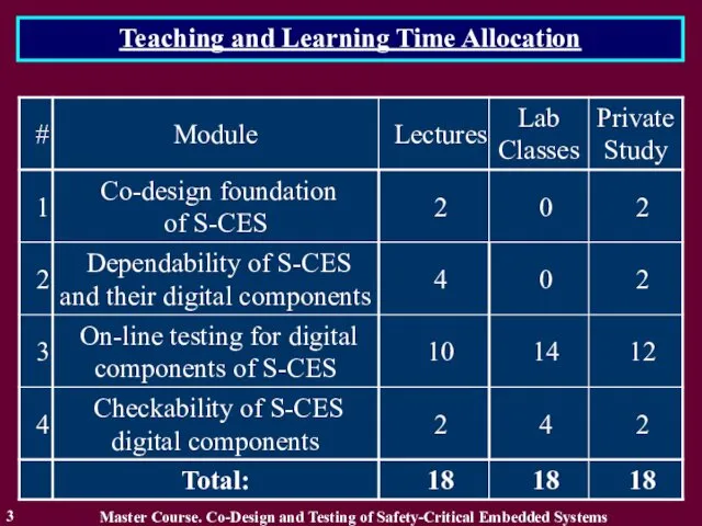
Teaching and Learning Time Allocation
Master Course. Co-Design and Testing of Safety-Critical
Teaching and Learning Time Allocation
Master Course. Co-Design and Testing of Safety-Critical
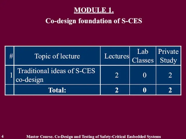
MODULE 1.
Co-design foundation of S-CES
4
Master Course. Co-Design and Testing
MODULE 1.
Co-design foundation of S-CES
4
Master Course. Co-Design and Testing
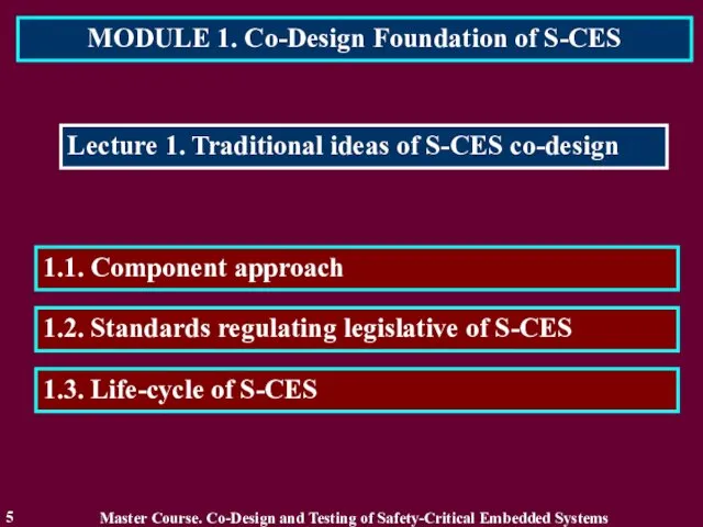
MODULE 1. Co-Design Foundation of S-CES
5
Lecture 1. Traditional ideas of S-CES
MODULE 1. Co-Design Foundation of S-CES
5
Lecture 1. Traditional ideas of S-CES
1.1. Component Approach
6
Component-based technology is information technology based on component representation
1.1. Component Approach
6
Component-based technology is information technology based on component representation
1.2. Standards regulating legislative of S-CES
7
IEC 61508 (general for
electronics
1.2. Standards regulating legislative of S-CES
7
IEC 61508 (general for
electronics
1.2. Standards regulating legislative of S-CES
8
IEC 61508 – Safety of
1.2. Standards regulating legislative of S-CES
8
IEC 61508 – Safety of

1.2. Standards regulating legislative of S-CES
9
Features of IEC 61508 standard
Master
1.2. Standards regulating legislative of S-CES
9
Features of IEC 61508 standard
Master
1.2. Standards regulating legislative of S-CES
10
IEC 61508 standard as foundation
1.2. Standards regulating legislative of S-CES
10
IEC 61508 standard as foundation
1.2. Standards regulating legislative of S-CES
11
IEC 61508 standard as foundation
1.2. Standards regulating legislative of S-CES
11
IEC 61508 standard as foundation
1.2. Standards regulating legislative of S-CES
12
IEC 61508 standard as foundation
1.2. Standards regulating legislative of S-CES
12
IEC 61508 standard as foundation
1.2. Standards regulating legislative of S-CES
13
IEC 61508 standard as foundation
1.2. Standards regulating legislative of S-CES
13
IEC 61508 standard as foundation
1.2. Standards regulating legislative of S-CES
14
IEC 61508 standard as foundation
1.2. Standards regulating legislative of S-CES
14
IEC 61508 standard as foundation

1.3. Life-cycle of S-CES
15
1. Development of signal formation algorithm block-diagram.
1. Stages
1.3. Life-cycle of S-CES
15
1. Development of signal formation algorithm block-diagram.
1. Stages

1.3. Life-cycle of S-CES
16
1. Block-diagrams according to control algorithms.
2. Results of
1.3. Life-cycle of S-CES
16
1. Block-diagrams according to control algorithms.
2. Results of
1.3. Life-cycle of S-CES
17
1. Verification of block-diagrams according to control algorithms.
3.
1.3. Life-cycle of S-CES
17
1. Verification of block-diagrams according to control algorithms.
3.
1.3. Life-cycle of S-CES
18
2. A life-cycle of FPGA-based S-CES
Master Course. Co-Design
1.3. Life-cycle of S-CES
18
2. A life-cycle of FPGA-based S-CES
Master Course. Co-Design

Reading List
19
Master Course. Co-Design and Testing of Safety-Critical Embedded Systems
Бахмач
Reading List
19
Master Course. Co-Design and Testing of Safety-Critical Embedded Systems
Бахмач

Conclusion
20
2. Component approach constitutes the use of library components developed
Conclusion
20
2. Component approach constitutes the use of library components developed
Questions and tasks
21
What is the S-CES?
What Traditional ideas of S-CES
Questions and tasks
21
What is the S-CES?
What Traditional ideas of S-CES
MODULE 2.
Dependability of S-CES
and their digital components
Master Course. Co-Design and
MODULE 2.
Dependability of S-CES
and their digital components
Master Course. Co-Design and
MODULE 2. Dependability of S-CES
and their digital components
23
Lecture 2. Foundation of
MODULE 2. Dependability of S-CES
and their digital components
23
Lecture 2. Foundation of
2.1. Introduction into Dependability
24
Increase of requirements to modern computer systems from
2.1. Introduction into Dependability
24
Increase of requirements to modern computer systems from

2.1.2. Related Works
25
Different aspects of Dependability, principles of construction and realization
2.1.2. Related Works
25
Different aspects of Dependability, principles of construction and realization

2.1.3. Definition of Dependability
26
Dependability is ability to avoid service failures that
2.1.3. Definition of Dependability
26
Dependability is ability to avoid service failures that
2.2. Dependability Threats
27
Dependability Threats - Faults,
Errors,
Failures.
Master Course. Co-Design
2.2. Dependability Threats
27
Dependability Threats - Faults,
Errors,
Failures.
Master Course. Co-Design
2.2. Dependability Threats
28
Master Course. Co-Design and Testing of Safety-Critical Embedded
2.2. Dependability Threats
28
Master Course. Co-Design and Testing of Safety-Critical Embedded

2.2. Dependability Threats
29
Master Course. Co-Design and Testing of Safety-Critical Embedded
2.2. Dependability Threats
29
Master Course. Co-Design and Testing of Safety-Critical Embedded
2.2. Dependability Threats
30
Master Course. Co-Design and Testing of Safety-Critical Embedded
2.2. Dependability Threats
30
Master Course. Co-Design and Testing of Safety-Critical Embedded
2.2. Dependability Threats
31
Fault error failure chain is a way from
2.2. Dependability Threats
31
Fault error failure chain is a way from
2.3. Dependability Attributes
32
Readiness for usage – Availability.
Continuity of service –
2.3. Dependability Attributes
32
Readiness for usage – Availability.
Continuity of service –
2.4. Dependability Measures
33
The alternation of correct-incorrect service delivery is quantified
2.4. Dependability Measures
33
The alternation of correct-incorrect service delivery is quantified
2.5. Safety and Reliability
34
Safety is an extension of Reliability:
the
2.5. Safety and Reliability
34
Safety is an extension of Reliability:
the
2.6. Forms of Dependability Requirements
35
Availability: – “The database must be
2.6. Forms of Dependability Requirements
35
Availability: – “The database must be

2.7. The Means to attain Dependability Techniques
36
The development of a
2.7. The Means to attain Dependability Techniques
36
The development of a
2.7.1. Fault Prevention
37
Fault Prevention is attained by quality control techniques
2.7.1. Fault Prevention
37
Fault Prevention is attained by quality control techniques
2.7.2. Fault Removal
38
Fault Removal is performed both during the development,
2.7.2. Fault Removal
38
Fault Removal is performed both during the development,

2.7.2.1. Fault Removal during Development
39
Verification Techniques can be classified according
2.7.2.1. Fault Removal during Development
39
Verification Techniques can be classified according
2.7.2.2. Fault Removal during the Operational Life
40
Fault Removal during the
2.7.2.2. Fault Removal during the Operational Life
40
Fault Removal during the
2.7.3. Fault Forecasting
41
Fault Forecasting is conducted by performing an evaluation
2.7.3. Fault Forecasting
41
Fault Forecasting is conducted by performing an evaluation

Reading List
42
Master Course. Co-Design and Testing of Safety-Critical Embedded Systems
Бахмач Е.С.,
Reading List
42
Master Course. Co-Design and Testing of Safety-Critical Embedded Systems
Бахмач Е.С.,
Conclusion
43
2. Dependability threats consist of Faults, Errors and Failures.
1. Dependability
Conclusion
43
2. Dependability threats consist of Faults, Errors and Failures.
1. Dependability
Questions and tasks
44
What is the Dependability?
What Dependability threats of S-CES
Questions and tasks
44
What is the Dependability?
What Dependability threats of S-CES
MODULE 2. Dependability of S-CES
and their digital components
45
Lecture 3. Fault Tolerance
MODULE 2. Dependability of S-CES
and their digital components
45
Lecture 3. Fault Tolerance
3.1. Introduction into Fault Tolerance
46
Fault Tolerance is a base
3.1. Introduction into Fault Tolerance
46
Fault Tolerance is a base

3.1.2. Related Works
47
Master Course. Co-Design and Testing of Safety-Critical Embedded Systems
1.
3.1.2. Related Works
47
Master Course. Co-Design and Testing of Safety-Critical Embedded Systems
1.

3.1.3. Definition of Fault Tolerance
48
Fault Tolerance is intended to preserve the
3.1.3. Definition of Fault Tolerance
48
Fault Tolerance is intended to preserve the
3.2. Error Detection
49
Error Detection defines the presence of an error.
There
3.2. Error Detection
49
Error Detection defines the presence of an error.
There
3.3. Recovery
50
System Recovery transforms a system state that contains one
3.3. Recovery
50
System Recovery transforms a system state that contains one
3.3.1. Error Handling
51
Error Handling eliminates errors from the system state.
Error
3.3.1. Error Handling
51
Error Handling eliminates errors from the system state.
Error
3.3.2. Fault Handling
52
Fault Handling prevents located faults from being activated
3.3.2. Fault Handling
52
Fault Handling prevents located faults from being activated

3.4. Fault-Tolerant Technologies
53
Fault-Tolerant Technologies traditionally used in co-design of S-CES:
Use
3.4. Fault-Tolerant Technologies
53
Fault-Tolerant Technologies traditionally used in co-design of S-CES:
Use

3.4.1 Use of Detecting and Correcting codes
54
Residue check equations:
KA +
3.4.1 Use of Detecting and Correcting codes
54
Residue check equations:
KA +
55
Blocks BCA and BCB check the operands A and B
55
Blocks BCA and BCB check the operands A and B
56
Code K3 K2 K1 defines number of an erroneous bit 1,
56
Code K3 K2 K1 defines number of an erroneous bit 1,
57
Circuit for Memory Recover using Hamming Correcting Code
Master Course. Co-Design
57
Circuit for Memory Recover using Hamming Correcting Code
Master Course. Co-Design

Generating Matrix
of correcting code for Majority Structures
Majority circuit
3.4.2. Majority Structures
58
Generating Matrix
of correcting code for Majority Structures
Majority circuit
3.4.2. Majority Structures
58
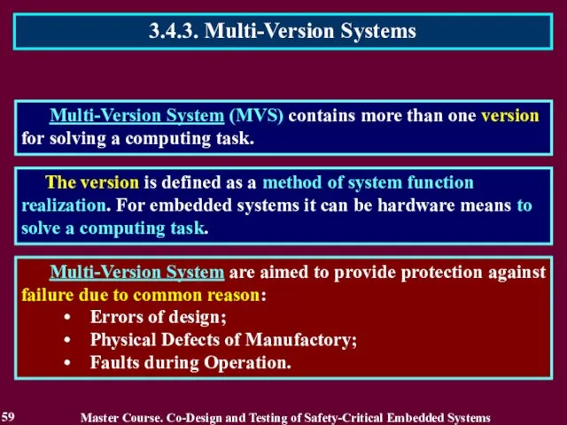
Multi-Version System (MVS) contains more than one version for solving
Multi-Version System (MVS) contains more than one version for solving
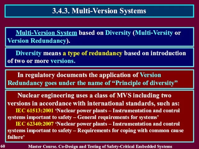
Multi-Version System based on Diversity (Multi-Versity or Version Redundancy).
Diversity means a
Multi-Version System based on Diversity (Multi-Versity or Version Redundancy).
Diversity means a
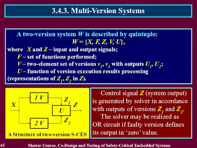
A two-version system W is described by quintuple:
W = {X,
A two-version system W is described by quintuple:
W = {X,
A Classification of Diversity Types
3.4.3. Multi-Version Systems
62
Master Course. Co-Design and
A Classification of Diversity Types
3.4.3. Multi-Version Systems
62
Master Course. Co-Design and
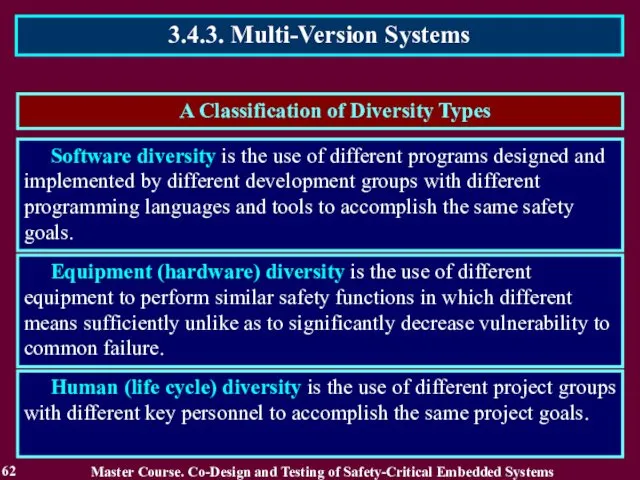
A Classification of Diversity Types
3.4.3. Multi-Version Systems
63
Master Course. Co-Design and
A Classification of Diversity Types
3.4.3. Multi-Version Systems
63
Master Course. Co-Design and

3.4.3. Multi-Version Systems
64
Master Course. Co-Design and Testing of Safety-Critical Embedded Systems
3.4.3. Multi-Version Systems
64
Master Course. Co-Design and Testing of Safety-Critical Embedded Systems
Two-version system is considered as simplest MVS. It has only two
Two-version system is considered as simplest MVS. It has only two
Computer Systems with Strongly Connected Versions is MVS for which exception
Computer Systems with Strongly Connected Versions is MVS for which exception
Basis for SVS creation are CS that have a modular structure
Basis for SVS creation are CS that have a modular structure

A minimum quantity of versions in a SVS is three
A
A minimum quantity of versions in a SVS is three
A
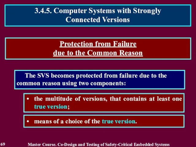
The SVS becomes protected from failure due to the common reason
The SVS becomes protected from failure due to the common reason
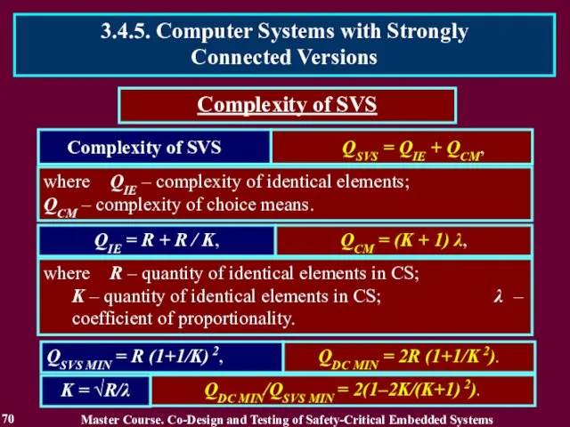
Complexity of SVS
QIE = R + R / K,
QSVS MIN = R (1+1/K) 2,
QCM = (K + 1) λ,
Complexity of SVS
QDC MIN/QSVS
Complexity of SVS
QIE = R + R / K,
QSVS MIN = R (1+1/K) 2,
QCM = (K + 1) λ,
Complexity of SVS
QDC MIN/QSVS
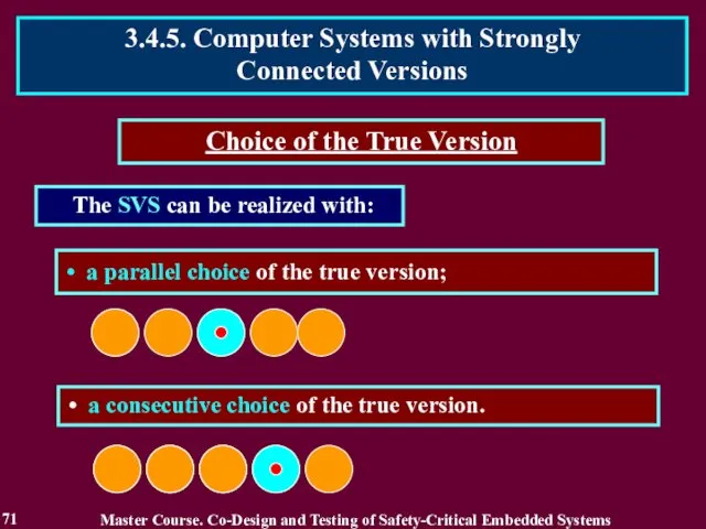
The SVS can be realized with:
Choice of the True Version
The SVS can be realized with:
Choice of the True Version
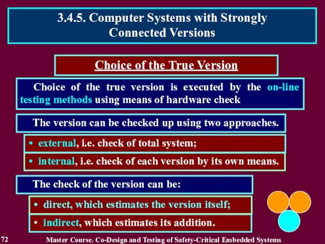
Choice of the true version is executed by the on-line testing
Choice of the true version is executed by the on-line testing
A parallel choice of the true version is realized by the
A parallel choice of the true version is realized by the
Reading List
74
Master Course. Co-Design and Testing of Safety-Critical Embedded Systems
Бахмач Е.С.,
Reading List
74
Master Course. Co-Design and Testing of Safety-Critical Embedded Systems
Бахмач Е.С.,
Conclusion
75
1. Fault Tolerance is a base of any S-CES and
Conclusion
75
1. Fault Tolerance is a base of any S-CES and
Questions and tasks
76
What is the Fault Tolerance?
What kinds of the
Questions and tasks
76
What is the Fault Tolerance?
What kinds of the
MODULE 3.
On-line testing for digital component of S-CES
Master Course. Co-Design
MODULE 3.
On-line testing for digital component of S-CES
Master Course. Co-Design
MODULE 3. On-line testing
for digital components of S-CES
78
Lecture 4. Processing
MODULE 3. On-line testing
for digital components of S-CES
78
Lecture 4. Processing
4.1. Introduction into On-Line Testing
79
On-Line Testing is a base
4.1. Introduction into On-Line Testing
79
On-Line Testing is a base
4.1.2. Related Works
80
Master Course. Co-Design and Testing of Safety-Critical Embedded Systems
1.
4.1.2. Related Works
80
Master Course. Co-Design and Testing of Safety-Critical Embedded Systems
1.
4.1.3. Definition of On-Line Testing
81
It has many names:
concurrent checking
4.1.3. Definition of On-Line Testing
81
It has many names:
concurrent checking
4.2. Stages of On-Line Testing Development
82
the initial stage;
stage of becoming
4.2. Stages of On-Line Testing Development
82
the initial stage;
stage of becoming
The basis of the theory and practice of on-line testing of
The basis of the theory and practice of on-line testing of
The noises on air deformed transmitted messages.
84
4.2.1. Initial Stage of
The noises on air deformed transmitted messages.
84
4.2.1. Initial Stage of
To transfer correct message the redundant coding the data with help
To transfer correct message the redundant coding the data with help

To transfer correct message the redundant coding the data with help
To transfer correct message the redundant coding the data with help
To transfer correct message the redundant coding the data with help
To transfer correct message the redundant coding the data with help
To transfer correct message the redundant coding the data with help
To transfer correct message the redundant coding the data with help
the elements of the transmitted message are coded by numbers
the elements of the transmitted message are coded by numbers
The coder transforms they into words of the group code, which
The coder transforms they into words of the group code, which
The decoder detects an error if it is non-code word. The
The decoder detects an error if it is non-code word. The
In case the all equations are true, it is codeword, i.e.
In case the all equations are true, it is codeword, i.e.
The equations defines the error detection circuit. If the circuit detects
The equations defines the error detection circuit. If the circuit detects

Coders and decoders were considered absolutely reliable during message transfer and
Coders and decoders were considered absolutely reliable during message transfer and
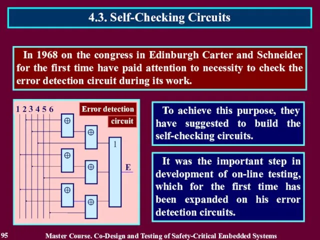
In 1968 on the congress in Edinburgh Carter and Schneider for
In 1968 on the congress in Edinburgh Carter and Schneider for
A circuit is fault-secure for a set of faults F if
A circuit is fault-secure for a set of faults F if
A circuit is fault-secure for a set of faults F
A circuit is fault-secure for a set of faults F
A circuit is fault-secure for a set of faults F
A circuit is fault-secure for a set of faults F
The self-testing property is aimed to create a condition at which
The self-testing property is aimed to create a condition at which
The self-testing property is aimed to create a condition at which
The self-testing property is aimed to create a condition at which
The self-testing property is aimed to create a condition at which
The self-testing property is aimed to create a condition at which
The self-testing property is aimed to create a condition at which
The self-testing property is aimed to create a condition at which

According to these definitions the designed circuit is not self-checking
According to these definitions the designed circuit is not self-checking
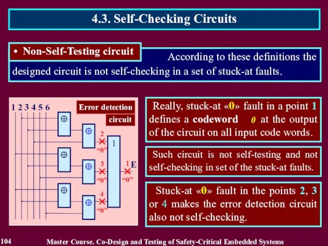
Such circuit is not self-testing and not self-checking in set of
Such circuit is not self-testing and not self-checking in set of

4.3. Self-Checking Circuits
In order to design self-checking circuit the bits 4,
4.3. Self-Checking Circuits
In order to design self-checking circuit the bits 4,
If even one input pair contains equal bits the output pair
If even one input pair contains equal bits the output pair
If even one input pair contains equal bits the output pair
If even one input pair contains equal bits the output pair
The next decades on-line testing has received wide development in a
The next decades on-line testing has received wide development in a

The definitions of self-checking circuit have executed an important role in
The definitions of self-checking circuit have executed an important role in
However, the definitions of self-checking circuit have also negative influence on
However, the definitions of self-checking circuit have also negative influence on
The correct circuit calculates a reliable result, and non-reliable result is
The correct circuit calculates a reliable result, and non-reliable result is
What is a purpose of on-line testing?
Today the purpose of on-line
What is a purpose of on-line testing?
Today the purpose of on-line
What is a purpose of on-line testing?
Today the purpose of on-line
What is a purpose of on-line testing?
Today the purpose of on-line
Creation of the critical conditions is
the best way to detect
Creation of the critical conditions is
the best way to detect
Search of faults during computations defies common sense as detection of
Search of faults during computations defies common sense as detection of
Declared purpose contradicts actual application.
The errors are produced by transient and
Declared purpose contradicts actual application.
The errors are produced by transient and
Purpose of on-line testing is to answer a question “Is the
Purpose of on-line testing is to answer a question “Is the
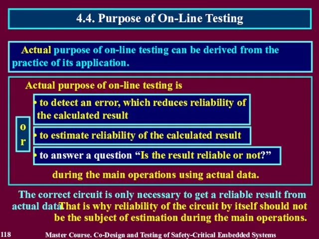
Actual purpose of on-line testing is
to detect an error, which
Actual purpose of on-line testing is
to detect an error, which
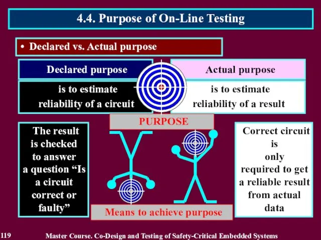
Declared purpose
Declared vs. Actual purpose
Actual purpose
is to estimate reliability
Declared purpose
Declared vs. Actual purpose
Actual purpose
is to estimate reliability
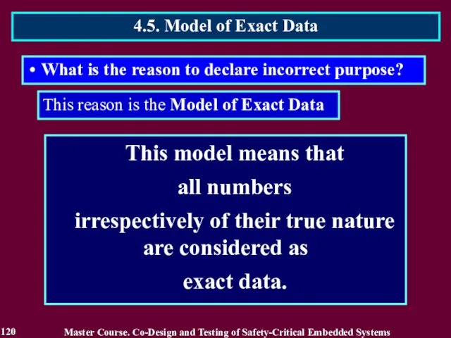
This model means that
all numbers
irrespectively of their true nature
This model means that
all numbers
irrespectively of their true nature
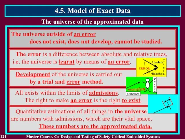
The universe of the approximated data
The universe outside of an error
The universe of the approximated data
The universe outside of an error
All values of codeword can be mapped to the respective ordinal
All values of codeword can be mapped to the respective ordinal

The exact data model means that all numbers irrespectively of their
The exact data model means that all numbers irrespectively of their
On-line testing is based on the Model of Exact Data
This
On-line testing is based on the Model of Exact Data
This
On-line testing is based on the Model of Exact Data
All
On-line testing is based on the Model of Exact Data
All
Every error in exact result makes it non-reliable and the computing
Every error in exact result makes it non-reliable and the computing
self-checking circuit techniques to obtain reliable results on correct circuit only;
self-checking circuit techniques to obtain reliable results on correct circuit only;
Reading List
128
Master Course. Co-Design and Testing of Safety-Critical Embedded Systems
Дрозд А.
Reading List
128
Master Course. Co-Design and Testing of Safety-Critical Embedded Systems
Дрозд А.
Conclusion
129
1. On-line testing is a base of any S-CES and
Conclusion
129
1. On-line testing is a base of any S-CES and
Questions and tasks
130
What names of on-line testing do you know?
Recite
Questions and tasks
130
What names of on-line testing do you know?
Recite

MODULE 3. On-line testing
for digital components of S-CES
Lecture 5. Approximate
MODULE 3. On-line testing
for digital components of S-CES
Lecture 5. Approximate
5.1. Introduction into Approximate Data Processing
The majority of processed
5.1. Introduction into Approximate Data Processing
The majority of processed

5.1.2. Related Works
Master Course. Co-Design and Testing of Safety-Critical Embedded Systems
1.
5.1.2. Related Works
Master Course. Co-Design and Testing of Safety-Critical Embedded Systems
1.
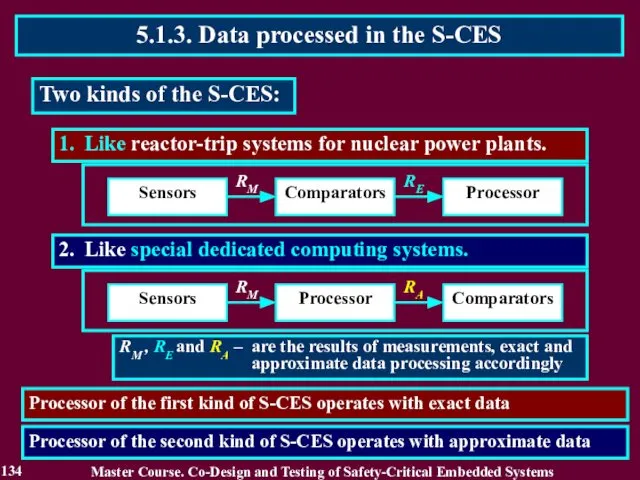
2. Like special dedicated computing systems.
1. Like reactor-trip systems for
2. Like special dedicated computing systems.
1. Like reactor-trip systems for
Approximate data
Approximate data contain results of measurements and are processed in
Approximate data
Approximate data contain results of measurements and are processed in
Normal form of data representation
Let a computer works with 8-bit codeword
Normal form of data representation
Let a computer works with 8-bit codeword
Normal form of data representation
So, Normal form of data representation using
Normal form of data representation
So, Normal form of data representation using
Normal form of data representation
Normal form m × BE represents data
Normal form of data representation
Normal form m × BE represents data
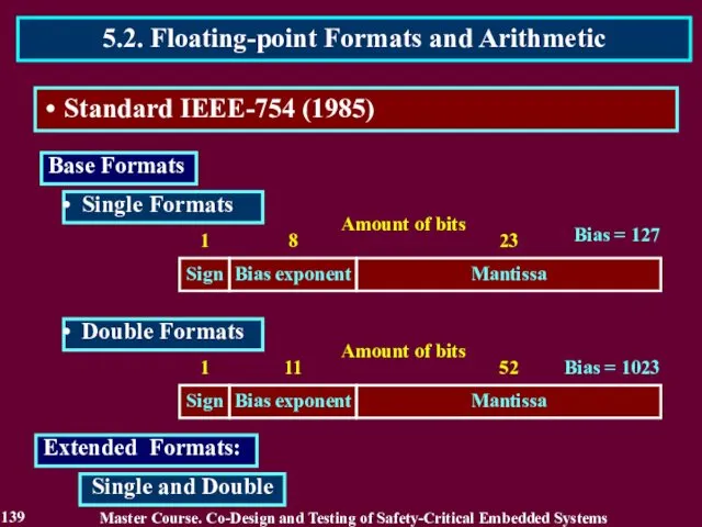
Extended Formats:
Master Course. Co-Design and Testing of Safety-Critical Embedded Systems
5.2.
Extended Formats:
Master Course. Co-Design and Testing of Safety-Critical Embedded Systems
5.2.
Master Course. Co-Design and Testing of Safety-Critical Embedded Systems
5.2. Floating-point Formats
Master Course. Co-Design and Testing of Safety-Critical Embedded Systems
5.2. Floating-point Formats
Master Course. Co-Design and Testing of Safety-Critical Embedded Systems
5.2. Floating-point Formats
Master Course. Co-Design and Testing of Safety-Critical Embedded Systems
5.2. Floating-point Formats
Master Course. Co-Design and Testing of Safety-Critical Embedded Systems
5.2. Floating-point Formats
Master Course. Co-Design and Testing of Safety-Critical Embedded Systems
5.2. Floating-point Formats
5.3. Complete and Truncated Operations
143
Master Course. Co-Design and Testing of Safety-Critical
5.3. Complete and Truncated Operations
143
Master Course. Co-Design and Testing of Safety-Critical
5.3. Complete and Truncated Operations
Truncated multiplication
144
Master Course. Co-Design and Testing
5.3. Complete and Truncated Operations
Truncated multiplication
144
Master Course. Co-Design and Testing
Master Course. Co-Design and Testing of Safety-Critical Embedded Systems
5.3. Complete and
Master Course. Co-Design and Testing of Safety-Critical Embedded Systems
5.3. Complete and

Master Course. Co-Design and Testing of Safety-Critical Embedded Systems
5.3. Complete and
Master Course. Co-Design and Testing of Safety-Critical Embedded Systems
5.3. Complete and
Master Course. Co-Design and Testing of Safety-Critical Embedded Systems
5.3. Complete and
Master Course. Co-Design and Testing of Safety-Critical Embedded Systems
5.3. Complete and
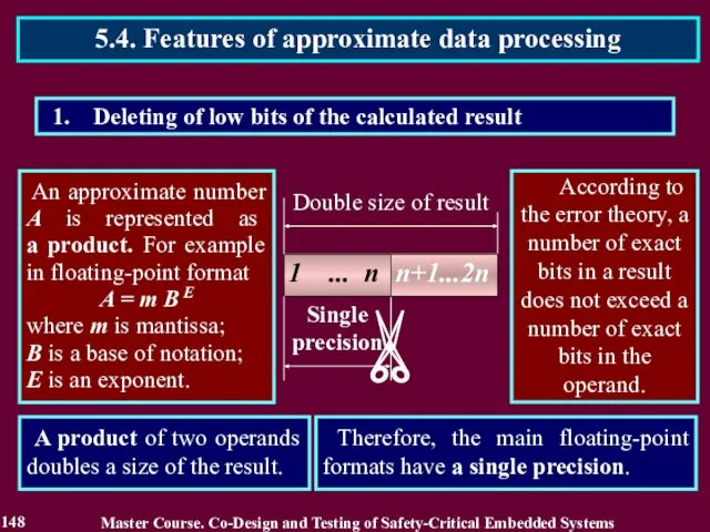
Deleting of low bits of the calculated result
An approximate number
Deleting of low bits of the calculated result
An approximate number
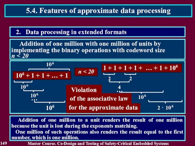
Addition of one million with one million of units by
Addition of one million with one million of units by
To restore the associative law, the size of the codeword
To restore the associative law, the size of the codeword

This action is frequently executed in such operations as addition, subtraction
This action is frequently executed in such operations as addition, subtraction
This action is executed with results in such operations as addition,
This action is executed with results in such operations as addition,
The error produced by a fault of the computing circuit considered
The error produced by a fault of the computing circuit considered
1. Error elimination with discarded bits of the result
K1 = n / nс
K1 = 0.5
The faulty circuit
1. Error elimination with discarded bits of the result
K1 = n / nс
K1 = 0.5
The faulty circuit

K2 = nE / n
nE and n are the number of exact bits and total number of bits
K2 = nE / n
nE and n are the number of exact bits and total number of bits

OS and OC are the hardware overhead of computing circuits preceding a shifter and
OS and OC are the hardware overhead of computing circuits preceding a shifter and

1 ... n-d
1 ... n-d
OS and OC are the hardware overhead of computing circuits
1 ... n-d
1 ... n-d
OS and OC are the hardware overhead of computing circuits
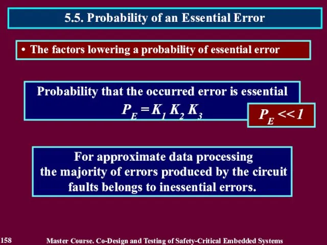
Probability that the occurred error is essential
PE = K1 K2 K3
PE << 1
For approximate
Probability that the occurred error is essential
PE = K1 K2 K3
PE << 1
For approximate
Reading List
159
Master Course. Co-Design and Testing of Safety-Critical Embedded Systems
Полин Е.
Reading List
159
Master Course. Co-Design and Testing of Safety-Critical Embedded Systems
Полин Е.
Conclusion
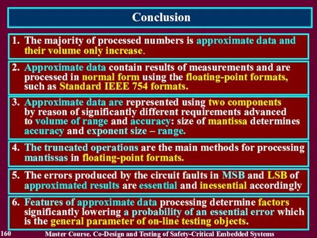
160
1. The majority of processed numbers is approximate data and
Conclusion
160
1. The majority of processed numbers is approximate data and

Questions and tasks
161
What role do the approximate data play in computer
Questions and tasks
161
What role do the approximate data play in computer

MODULE 3. On-line testing
for digital components of S-CES
Lecture 6. Reliability
MODULE 3. On-line testing
for digital components of S-CES
Lecture 6. Reliability
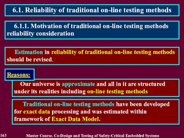
6.1. Reliability of traditional on-line testing methods
Estimation in reliability of
6.1. Reliability of traditional on-line testing methods
Estimation in reliability of
6.1.2. Related Works
Master Course. Co-Design and Testing of Safety-Critical Embedded Systems
1.
6.1.2. Related Works
Master Course. Co-Design and Testing of Safety-Critical Embedded Systems
1.
Traditionally, reliability of on-line testing method is estimated and considered as
Traditionally, reliability of on-line testing method is estimated and considered as
Reliability of on-line testing method can be considered using unit-side square.
Reliability of on-line testing method can be considered using unit-side square.
Reliability of on-line testing methods is defined on dependence of the
Reliability of on-line testing methods is defined on dependence of the
Reliability of on-line testing methods is defined on dependence of the
Reliability of on-line testing methods is defined on dependence of the
Traditional on-line testing methods based on totally self-checking circuit theory have
Traditional on-line testing methods based on totally self-checking circuit theory have
1. Traditional on-line testing methods based on self-checking circuit theory
1. Traditional on-line testing methods based on self-checking circuit theory

3. The part 2 demonstrates a new property of an
3. The part 2 demonstrates a new property of an

CURRENT VIEW
Existing on-line testing is applicable to any type of data.
A
CURRENT VIEW
Existing on-line testing is applicable to any type of data.
A

1. РE > 0,5
D = РD Р E + (1-РD )(1-Р
1. РE > 0,5
D = РD Р E + (1-РD )(1-Р
D = РD Р E + (1-РD )(1-Р E)
D↑= РD ↑
D = РD Р E + (1-РD )(1-Р E)
D↑= РD ↑

D↑= РD ↑ Р E ↑
(РE > 0,5) & (РD >
D↑= РD ↑ Р E ↑
(РE > 0,5) & (РD >

176
Master Course. Co-Design and Testing of Safety-Critical Embedded Systems
6.3. The first
176
Master Course. Co-Design and Testing of Safety-Critical Embedded Systems
6.3. The first
V{1 ÷ 2n}:
n = 14
k = 10
V{1 ÷ 2n}:
n = 14
k = 10
178
Master Course. Co-Design and Testing of Safety-Critical Embedded Systems
6.4. Residue checking
178
Master Course. Co-Design and Testing of Safety-Critical Embedded Systems
6.4. Residue checking
179
Master Course. Co-Design and Testing of Safety-Critical Embedded Systems
6.4. Residue checking
179
Master Course. Co-Design and Testing of Safety-Critical Embedded Systems
6.4. Residue checking
180
Master Course. Co-Design and Testing of Safety-Critical Embedded Systems
6.4. Residue checking
180
Master Course. Co-Design and Testing of Safety-Critical Embedded Systems
6.4. Residue checking
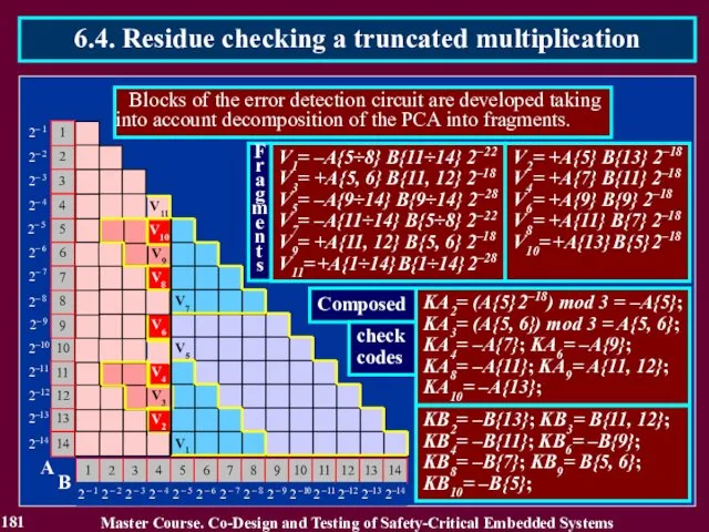
181
Master Course. Co-Design and Testing of Safety-Critical Embedded Systems
6.4. Residue checking
181
Master Course. Co-Design and Testing of Safety-Critical Embedded Systems
6.4. Residue checking
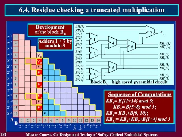
182
Master Course. Co-Design and Testing of Safety-Critical Embedded Systems
6.4. Residue checking
182
Master Course. Co-Design and Testing of Safety-Critical Embedded Systems
6.4. Residue checking

183
Master Course. Co-Design and Testing of Safety-Critical Embedded Systems
6.4. Residue checking
183
Master Course. Co-Design and Testing of Safety-Critical Embedded Systems
6.4. Residue checking
184
Master Course. Co-Design and Testing of Safety-Critical Embedded Systems
6.5. Residue checking
184
Master Course. Co-Design and Testing of Safety-Critical Embedded Systems
6.5. Residue checking
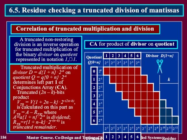
185
Master Course. Co-Design and Testing of Safety-Critical Embedded Systems
6.5. Residue checking
185
Master Course. Co-Design and Testing of Safety-Critical Embedded Systems
6.5. Residue checking
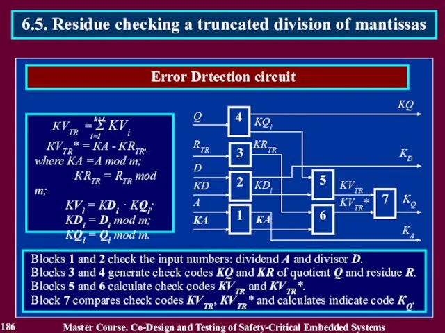
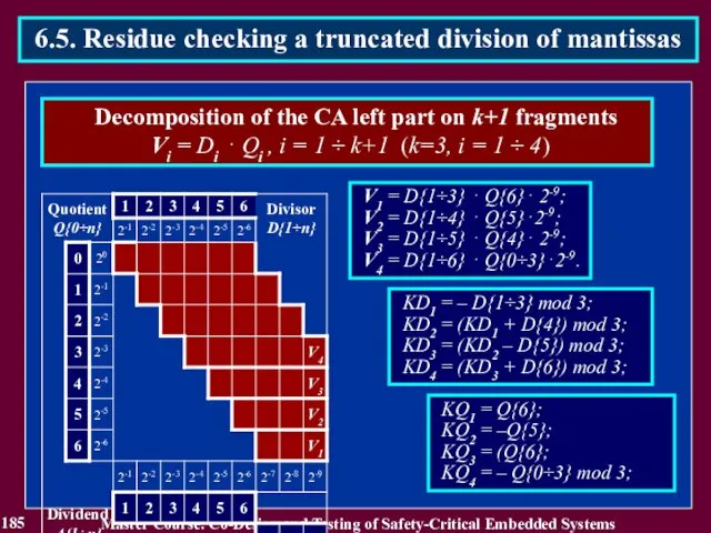
186
Master Course. Co-Design and Testing of Safety-Critical Embedded Systems
6.5. Residue checking
186
Master Course. Co-Design and Testing of Safety-Critical Embedded Systems
6.5. Residue checking
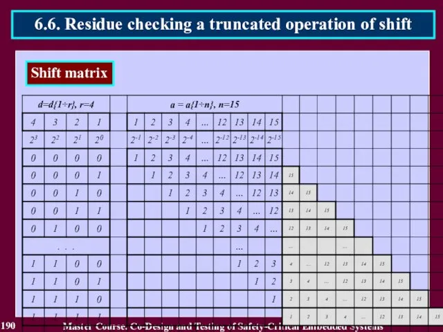
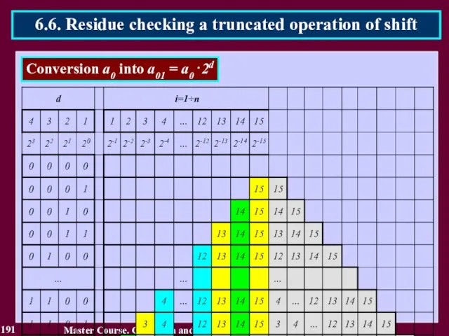
187
Master Course. Co-Design and Testing of Safety-Critical Embedded Systems
6.6. Residue checking
187
Master Course. Co-Design and Testing of Safety-Critical Embedded Systems
6.6. Residue checking
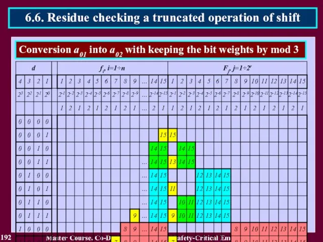
188
Master Course. Co-Design and Testing of Safety-Critical Embedded Systems
6.6. Residue checking
188
Master Course. Co-Design and Testing of Safety-Critical Embedded Systems
6.6. Residue checking
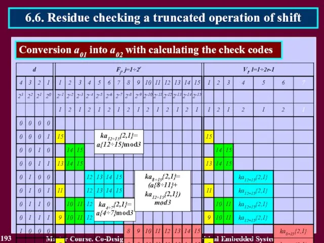
189
Master Course. Co-Design and Testing of Safety-Critical Embedded Systems
6.6. Residue checking
189
Master Course. Co-Design and Testing of Safety-Critical Embedded Systems
6.6. Residue checking
190
Master Course. Co-Design and Testing of Safety-Critical Embedded Systems
6.6. Residue checking
190
Master Course. Co-Design and Testing of Safety-Critical Embedded Systems
6.6. Residue checking
191
Master Course. Co-Design and Testing of Safety-Critical Embedded Systems
6.6. Residue checking
191
Master Course. Co-Design and Testing of Safety-Critical Embedded Systems
6.6. Residue checking
192
Master Course. Co-Design and Testing of Safety-Critical Embedded Systems
6.6. Residue checking
192
Master Course. Co-Design and Testing of Safety-Critical Embedded Systems
6.6. Residue checking
193
Master Course. Co-Design and Testing of Safety-Critical Embedded Systems
6.6. Residue checking
193
Master Course. Co-Design and Testing of Safety-Critical Embedded Systems
6.6. Residue checking

194
Master Course. Co-Design and Testing of Safety-Critical Embedded Systems
6.6. Residue checking
194
Master Course. Co-Design and Testing of Safety-Critical Embedded Systems
6.6. Residue checking
195
Master Course. Co-Design and Testing of Safety-Critical Embedded Systems
6.6. Residue checking
195
Master Course. Co-Design and Testing of Safety-Critical Embedded Systems
6.6. Residue checking
Reading List
196
Master Course. Co-Design and Testing of Safety-Critical Embedded Systems
1. Дрозд А.В.
Reading List
196
Master Course. Co-Design and Testing of Safety-Critical Embedded Systems
1. Дрозд А.В.
Conclusion
197
1. Traditional on-line testing methods have low reliability of approximated
Conclusion
197
1. Traditional on-line testing methods have low reliability of approximated
Questions and tasks
198
What is a reliability of the on-line testing methods?
What
Questions and tasks
198
What is a reliability of the on-line testing methods?
What

MODULE 3. On-line testing
for digital components of S-CES
Lecture 7. Increase
MODULE 3. On-line testing
for digital components of S-CES
Lecture 7. Increase
7.1. The second way for increasing on-line testing reliability
Second way
7.1. The second way for increasing on-line testing reliability
Second way

7.1.2. Related Works
Master Course. Co-Design and Testing of Safety-Critical Embedded Systems
1.
7.1.2. Related Works
Master Course. Co-Design and Testing of Safety-Critical Embedded Systems
1.
7.1. The second way for increasing on-line testing reliability
In case
7.1. The second way for increasing on-line testing reliability
In case
7.1. The second way for increasing on-line testing reliability
The main
7.1. The second way for increasing on-line testing reliability
The main
7.2. Checking with use of natural information redundancy
The code containing
7.2. Checking with use of natural information redundancy
The code containing
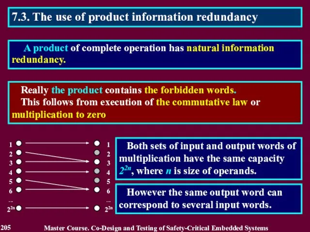
7.3. The use of product information redundancy
Really the product contains the
7.3. The use of product information redundancy
Really the product contains the
7.3. The use of product information redundancy
Fermat (1601-1665) supposition: the
7.3. The use of product information redundancy
Fermat (1601-1665) supposition: the

7.3. The use of product information redundancy
A prime number С =
7.3. The use of product information redundancy
A prime number С =
7.3. The use of product information redundancy
The checking method verifies
7.3. The use of product information redundancy
The checking method verifies
7.3. The use of product information redundancy
The checker consists of
7.3. The use of product information redundancy
The checker consists of
7.3. The use of product information redundancy
This checking method can
7.3. The use of product information redundancy
This checking method can
7.3. The use of product information redundancy
A probability of error
7.3. The use of product information redundancy
A probability of error
7.3. The use of product information redundancy
The described checking method
7.3. The use of product information redundancy
The described checking method
7.3. The use of product information redundancy
A prime number С* =
7.3. The use of product information redundancy
A prime number С* =
7.3. The use of product information redundancy
The checking method verifies
7.3. The use of product information redundancy
The checking method verifies
7.3. The use of product information redundancy
The checker consists of
7.3. The use of product information redundancy
The checker consists of
7.3. The use of product information redundancy
The checking method is
7.3. The use of product information redundancy
The checking method is

7.3. The use of product information redundancy
A probability of error
7.3. The use of product information redundancy
A probability of error
Block B1 calculates residue R by modulo m of result S = A2.
Block B1 calculates residue R by modulo m of result S = A2.

1. Calculation of square S = A2 and residue R =
1. Calculation of square S = A2 and residue R =
m = 15
4. Creation of a set Y of the typical
m = 15
4. Creation of a set Y of the typical
5. Creation of the error detection table using occurrences of allowed
5. Creation of the error detection table using occurrences of allowed
R = PD PE + ( 1 - PD ) (
R = PD PE + ( 1 - PD ) (
7.5. Checking by simplified operation
The checking method is based
7.5. Checking by simplified operation
The checking method is based
7.5. Checking by simplified operation
The method defines limiting conditions
7.5. Checking by simplified operation
The method defines limiting conditions
7.5. Checking by simplified operation
A model of simplification of
7.5. Checking by simplified operation
A model of simplification of
Block B1 uses LC for operands identifying the input words, on
Block B1 uses LC for operands identifying the input words, on

7.5. Checking by simplified operation
Two kinds of the check
7.5. Checking by simplified operation
Two kinds of the check
7.5. Checking by simplified operation
Initial data for checker design
7.5. Checking by simplified operation
Initial data for checker design

7.5. Checking by simplified operation
Master Course. Co-Design and Testing of
7.5. Checking by simplified operation
Master Course. Co-Design and Testing of
7.5. Checking by simplified operation
Master Course. Co-Design and Testing of
7.5. Checking by simplified operation
Master Course. Co-Design and Testing of
Reading List
231
Master Course. Co-Design and Testing of Safety-Critical Embedded Systems
1. Drozd
Reading List
231
Master Course. Co-Design and Testing of Safety-Critical Embedded Systems
1. Drozd

Conclusion
232
1. The second way can be realized using natural information
Conclusion
232
1. The second way can be realized using natural information

Questions and tasks
233
What is the second method for increasing a reliability
Questions and tasks
233
What is the second method for increasing a reliability
MODULE 3. On-line testing
for digital components of S-CES
Lecture 8. Checking
MODULE 3. On-line testing
for digital components of S-CES
Lecture 8. Checking
8.1. The third way for increasing on-line testing reliability
The third
8.1. The third way for increasing on-line testing reliability
The third

8.1.2. Related Works
Master Course. Co-Design and Testing of Safety-Critical Embedded Systems
1.
8.1.2. Related Works
Master Course. Co-Design and Testing of Safety-Critical Embedded Systems
1.
8.1. The third way for increasing on-line testing reliability
The main
8.1. The third way for increasing on-line testing reliability
The main
The logarithm checking is based on the use of the
The logarithm checking is based on the use of the
Check code КА of fixed-point number A is equal to
Check code КА of fixed-point number A is equal to
The check code is calculated using the truth form of
The check code is calculated using the truth form of
B{2}
1
A{2}
8.2. The logarithm checking
Master Course. Co-Design and Testing
B{2}
1
A{2}
8.2. The logarithm checking
Master Course. Co-Design and Testing
8.2. The logarithm checking
Master Course. Co-Design and Testing of Safety-Critical Embedded
8.2. The logarithm checking
Master Course. Co-Design and Testing of Safety-Critical Embedded
8.2. The logarithm checking
Master Course. Co-Design and Testing of Safety-Critical Embedded
8.2. The logarithm checking
Master Course. Co-Design and Testing of Safety-Critical Embedded
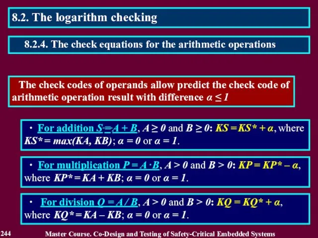
The check codes of operands allow predict the check code of
The check codes of operands allow predict the check code of
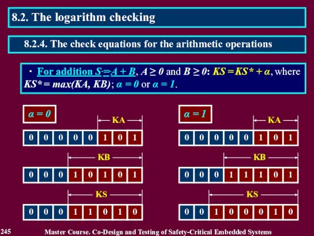
∙ For addition S = A + B, A ≥ 0 and B ≥ 0: KS = KS* + α, where
∙ For addition S = A + B, A ≥ 0 and B ≥ 0: KS = KS* + α, where
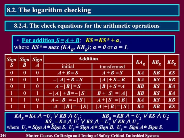
∙ For addition S = A + B: KS = KS* + α,
where KS* = max (KAR, KBR);
∙ For addition S = A + B: KS = KS* + α,
where KS* = max (KAR, KBR);
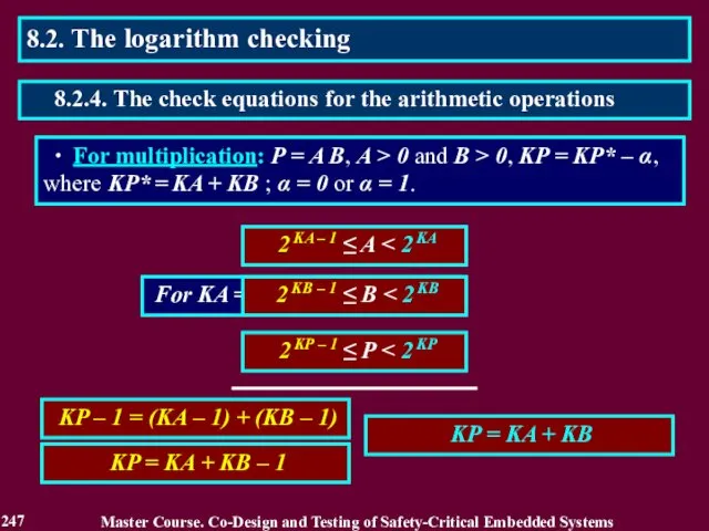
∙ For multiplication: P = A B, A > 0 and B > 0, KP = KP* – α, where KP* = KA + KB ;
∙ For multiplication: P = A B, A > 0 and B > 0, KP = KP* – α, where KP* = KA + KB ;
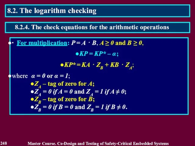
∙ For multiplication: P = A ⋅ B, A ≥ 0 and B ≥ 0,
KP = KP* – α ;
KP* = KA ⋅ ZB
∙ For multiplication: P = A ⋅ B, A ≥ 0 and B ≥ 0,
KP = KP* – α ;
KP* = KA ⋅ ZB
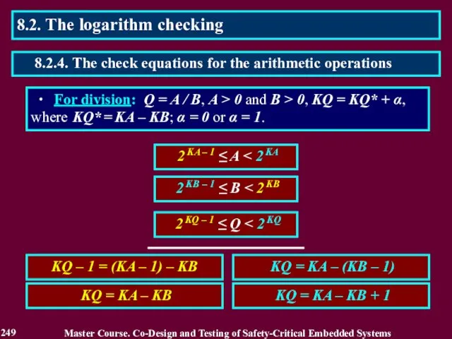
2 KA – 1 ≤ A < 2 KA
Master Course.
2 KA – 1 ≤ A < 2 KA
Master Course.
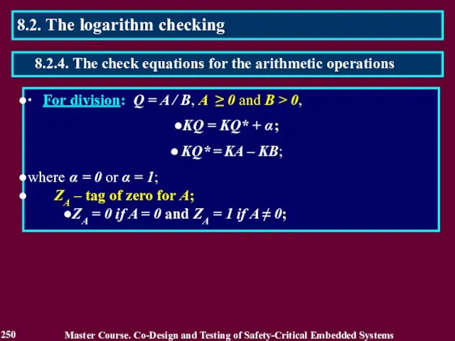
Master Course. Co-Design and Testing of Safety-Critical Embedded Systems
250
8.2. The logarithm
Master Course. Co-Design and Testing of Safety-Critical Embedded Systems
250
8.2. The logarithm
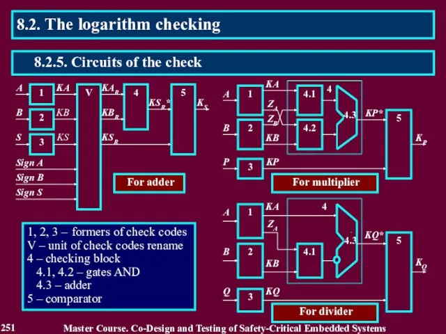
1, 2, 3 – formers of check codes
V – unit of
1, 2, 3 – formers of check codes
V – unit of
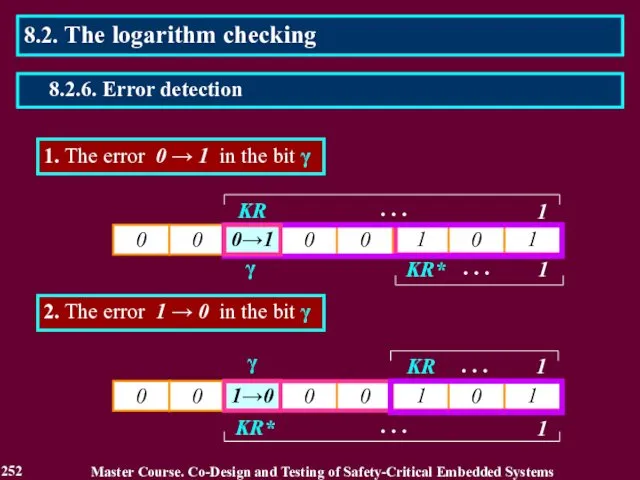
1. The error 0 → 1 in the bit γ
γ
2.
1. The error 0 → 1 in the bit γ
γ
2.
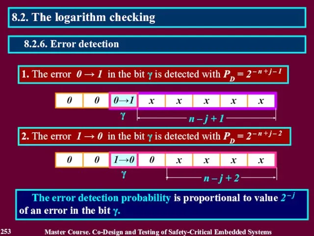
1. The error 0 → 1 in the bit γ is
1. The error 0 → 1 in the bit γ is
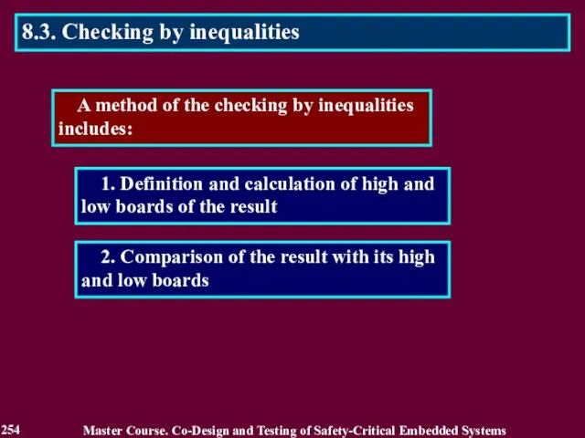
A method of the checking by inequalities includes:
2. Comparison
A method of the checking by inequalities includes:
2. Comparison

9/16
Y
X
YH
YL
Y = x2
0.5 ≤ x < 1
YH =
9/16
Y
X
YH
YL
Y = x2
0.5 ≤ x < 1
YH =
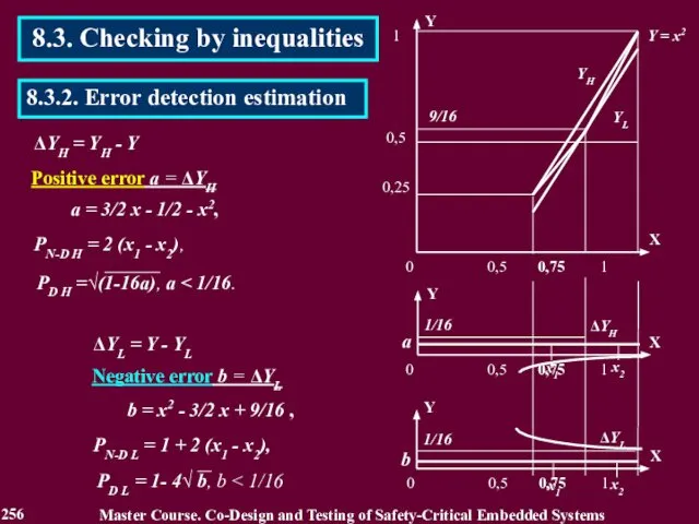
ΔYH = YH - Y
1/16
1/16
ΔYH
а = 3/2 x - 1/2
ΔYH = YH - Y
1/16
1/16
ΔYH
а = 3/2 x - 1/2
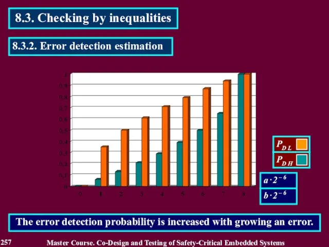
8.3. Checking by inequalities
Master Course. Co-Design and Testing of Safety-Critical Embedded
8.3. Checking by inequalities
Master Course. Co-Design and Testing of Safety-Critical Embedded
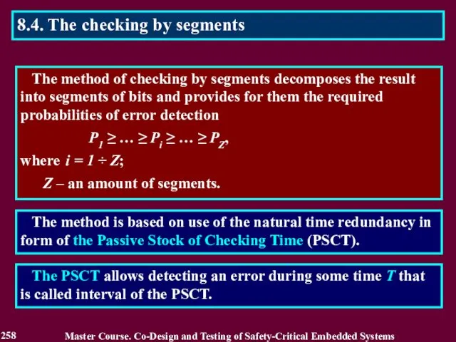
Master Course. Co-Design and Testing of Safety-Critical Embedded Systems
258
8.4. The checking
Master Course. Co-Design and Testing of Safety-Critical Embedded Systems
258
8.4. The checking
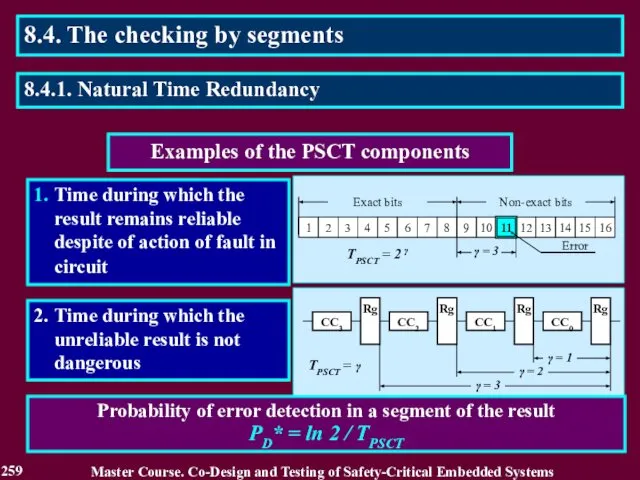
Examples of the PSCT components
1. Time during which the result remains
Examples of the PSCT components
1. Time during which the result remains

Estimation of reliability in checking the result
D = РDE + РSN
without
Estimation of reliability in checking the result
D = РDE + РSN
without
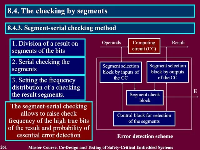
1. Division of a result on segments of the bits
2. Serial
1. Division of a result on segments of the bits
2. Serial
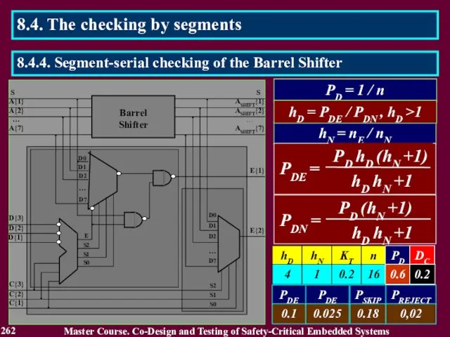
PD = 1 / n
hN = nE / nN
hD = PDE
PD = 1 / n
hN = nE / nN
hD = PDE
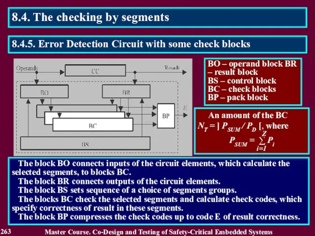
The block BO connects inputs of the circuit elements, which
The block BO connects inputs of the circuit elements, which

Array P of bits Pi j
in binary codes of probabilities Pi
Array P of bits Pi j
in binary codes of probabilities Pi
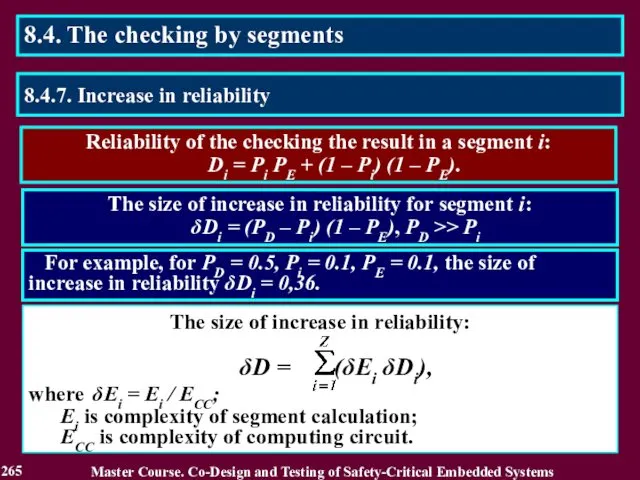
Reliability of the checking the result in a segment i:
Di = Pi PE + (1 – Pi) (1 – PE).
The
Reliability of the checking the result in a segment i:
Di = Pi PE + (1 – Pi) (1 – PE).
The

Reading List
266
Master Course. Co-Design and Testing of Safety-Critical Embedded Systems
1. Дрозд А. В. Использование
Reading List
266
Master Course. Co-Design and Testing of Safety-Critical Embedded Systems
1. Дрозд А. В. Использование
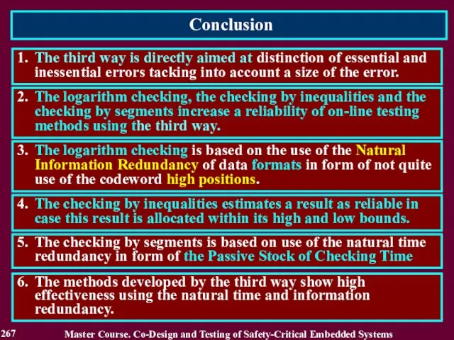
Conclusion
267
1. The third way is directly aimed at distinction of
Conclusion
267
1. The third way is directly aimed at distinction of
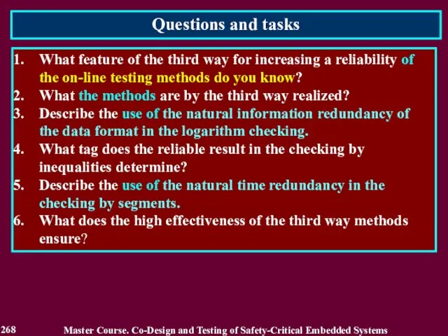
Questions and tasks
268
What feature of the third way for increasing a
Questions and tasks
268
What feature of the third way for increasing a
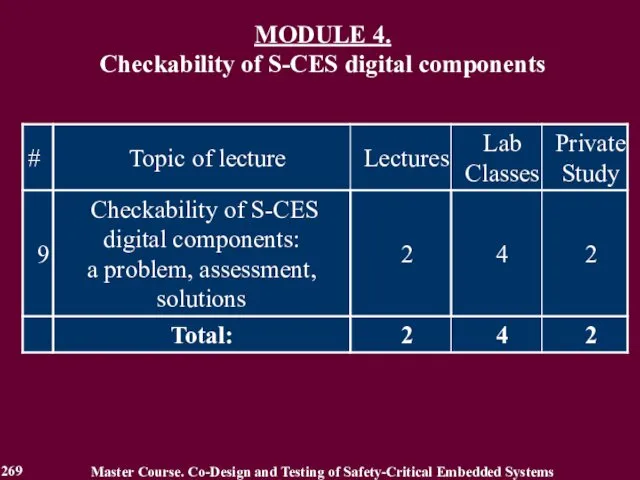
MODULE 4.
Checkability of S-CES digital components
Master Course. Co-Design and Testing
MODULE 4.
Checkability of S-CES digital components
Master Course. Co-Design and Testing

MODULE 4. Checkability of S-CES digital components
Lecture 9. Checkability of S-CES
MODULE 4. Checkability of S-CES digital components
Lecture 9. Checkability of S-CES

9.1. Introduction into checkability
Master Course. Co-Design and Testing of Safety-Critical Embedded
9.1. Introduction into checkability
Master Course. Co-Design and Testing of Safety-Critical Embedded
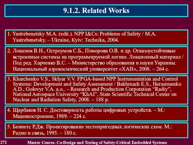
9.1.2. Related Works
Master Course. Co-Design and Testing of Safety-Critical Embedded Systems
1.
9.1.2. Related Works
Master Course. Co-Design and Testing of Safety-Critical Embedded Systems
1.
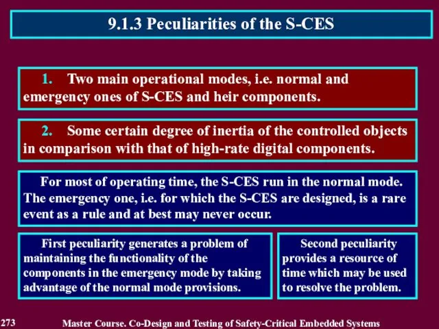
1. Two main operational modes, i.e. normal and emergency ones of
1. Two main operational modes, i.e. normal and emergency ones of

Both in the normal and emergency modes, the S-CES components operate
Both in the normal and emergency modes, the S-CES components operate

It is correct for the digital components operating in a single
It is correct for the digital components operating in a single

M(SN, SC, S),
where: SN is a component description characterizing its
M(SN, SC, S),
where: SN is a component description characterizing its
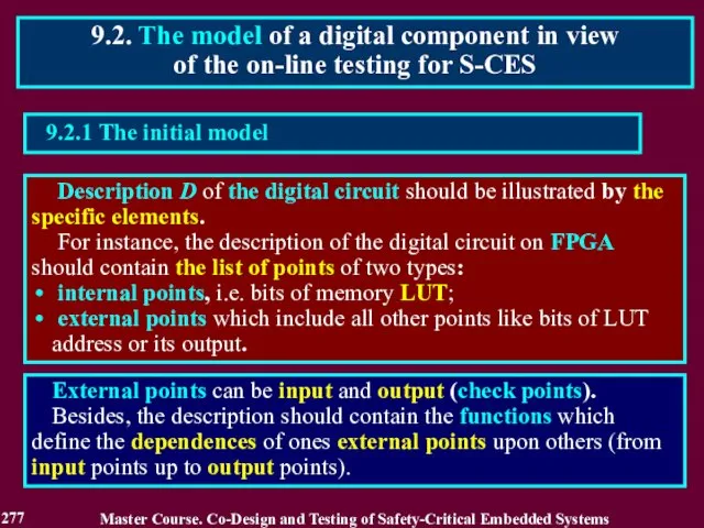
Description D of the digital circuit should be illustrated by
Description D of the digital circuit should be illustrated by
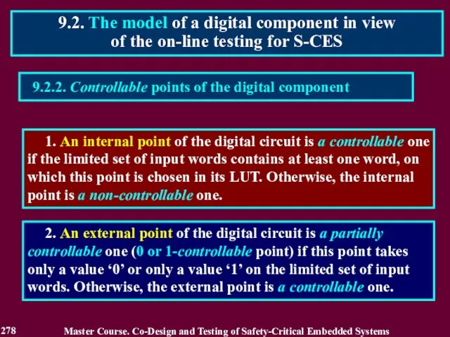
9.2.2. Controllable points of the digital component
1. An internal point
9.2.2. Controllable points of the digital component
1. An internal point
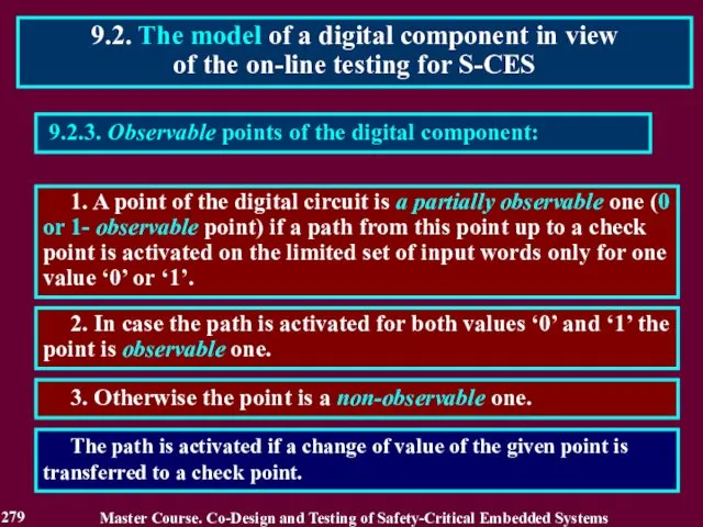
9.2.3. Observable points of the digital component:
1. A point of the
9.2.3. Observable points of the digital component:
1. A point of the
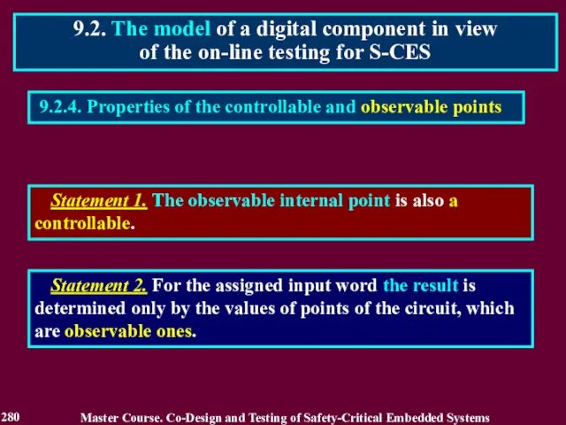
9.2.4. Properties of the controllable and observable points
9.2. The model of
9.2.4. Properties of the controllable and observable points
9.2. The model of
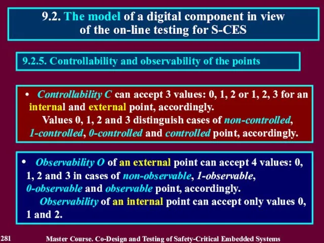
9.2.5. Controllability and observability of the points
Controllability C can accept
9.2.5. Controllability and observability of the points
Controllability C can accept
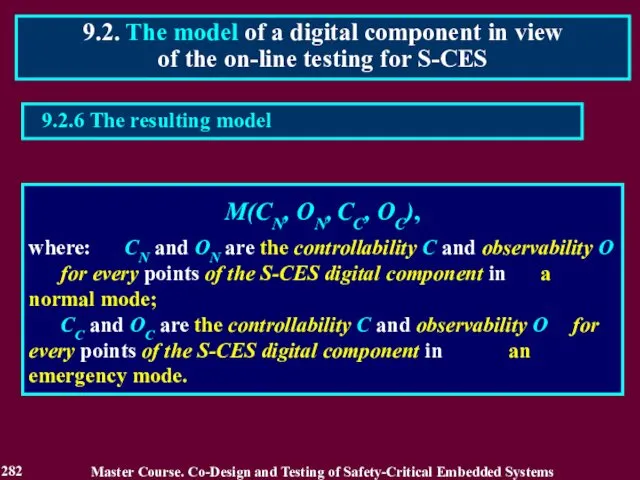
9.2. The model of a digital component in view of the
9.2. The model of a digital component in view of the
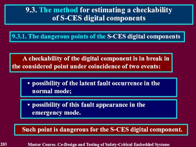
9.3.1. The dangerous points of the S-CES digital components
possibility of the
9.3.1. The dangerous points of the S-CES digital components
possibility of the

9.3.2. Possibilities of the latent fault accumulation in a normal
9.3.2. Possibilities of the latent fault accumulation in a normal
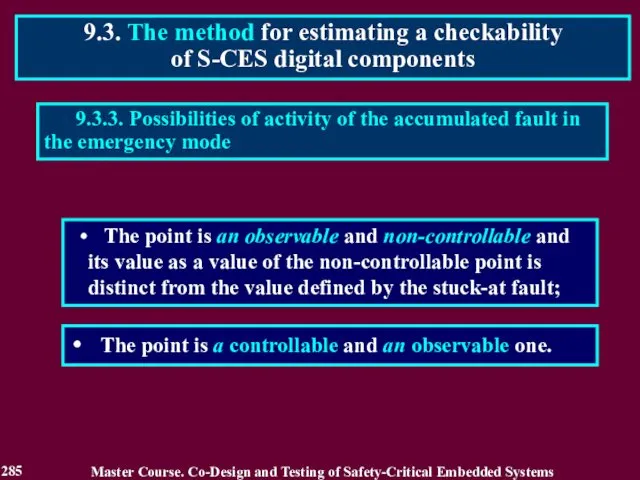
The point is an observable and non-controllable and its value
The point is an observable and non-controllable and its value
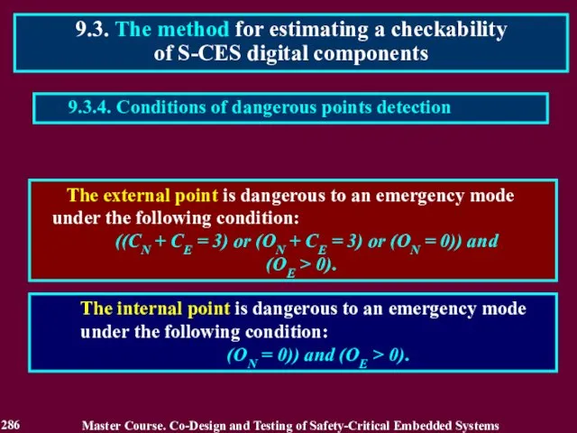
The external point is dangerous to an emergency mode under
The external point is dangerous to an emergency mode under
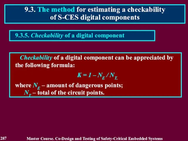
9.3.5. Checkability of a digital component
Checkability of a digital
9.3.5. Checkability of a digital component
Checkability of a digital
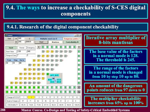
9.4.1. Research of the digital component checkability
9.4. The ways to
9.4.1. Research of the digital component checkability
9.4. The ways to

9.4.1. Research of the digital component checkability
9.4. The ways to
9.4.1. Research of the digital component checkability
9.4. The ways to
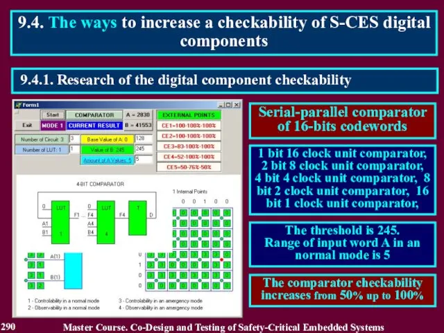
9.4.1. Research of the digital component checkability
9.4. The ways to
9.4.1. Research of the digital component checkability
9.4. The ways to
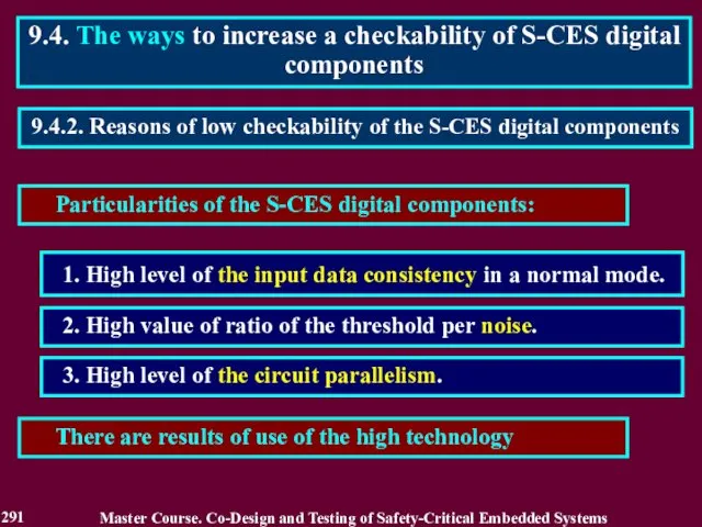
Particularities of the S-CES digital components:
1. High level of the input
Particularities of the S-CES digital components:
1. High level of the input
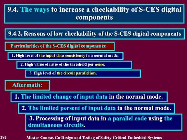
Particularities of the S-CES digital components:
9.4.2. Reasons of low checkability of
Particularities of the S-CES digital components:
9.4.2. Reasons of low checkability of
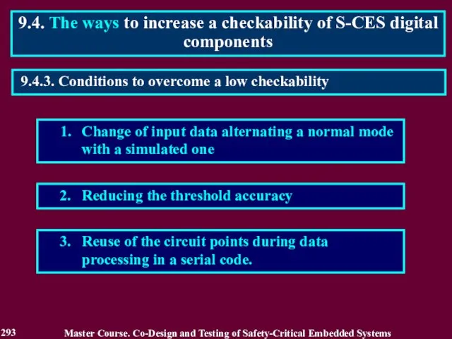
1. Change of input data alternating a normal mode with a
1. Change of input data alternating a normal mode with a
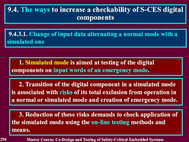
1. Simulated mode is aimed at testing of the digital components
1. Simulated mode is aimed at testing of the digital components
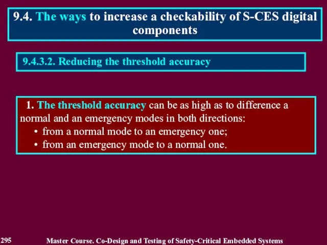
9.4.3.2. Reducing the threshold accuracy
1. The threshold accuracy can be
9.4.3.2. Reducing the threshold accuracy
1. The threshold accuracy can be
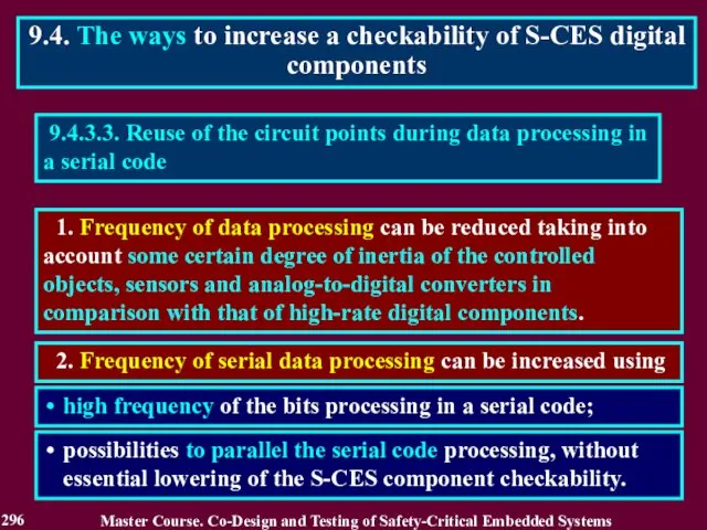
9.4.3.3. Reuse of the circuit points during data processing in
9.4.3.3. Reuse of the circuit points during data processing in
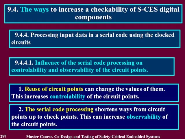
9.4.4.1. Influence of the serial code processing on controlability and observability
9.4.4.1. Influence of the serial code processing on controlability and observability
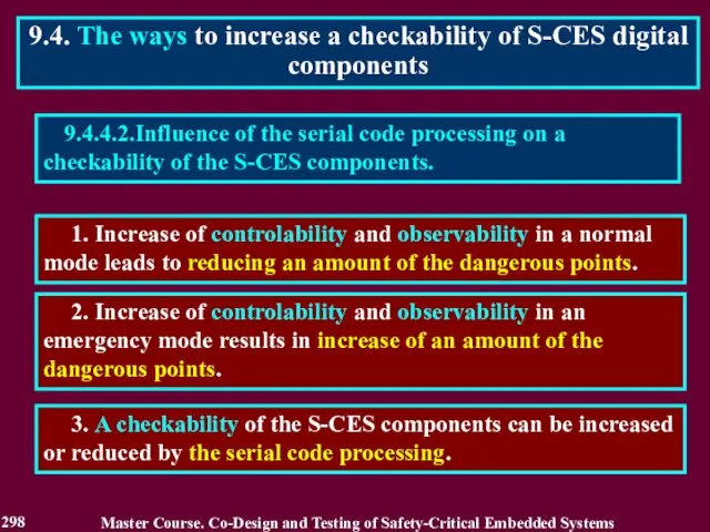
9.4.4.2.Influence of the serial code processing on a checkability of the
9.4.4.2.Influence of the serial code processing on a checkability of the
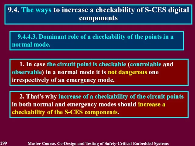
9.4.4.3. Dominant role of a checkability of the points in a
9.4.4.3. Dominant role of a checkability of the points in a
Reading List
300
Master Course. Co-Design and Testing of Safety-Critical Embedded Systems
Drozd A.
Reading List
300
Master Course. Co-Design and Testing of Safety-Critical Embedded Systems
Drozd A.
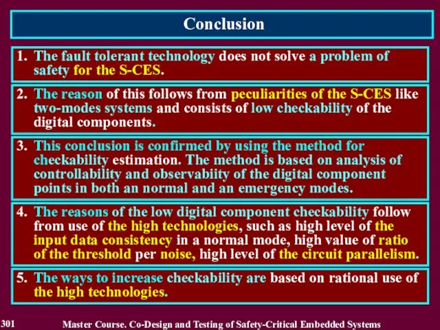
Conclusion
301
1. The fault tolerant technology does not solve a problem
Conclusion
301
1. The fault tolerant technology does not solve a problem
 Создание веб-сайтов
 Инструкция о порядке и очередности создания документов в 1С по методике начисления
 Компьютер как унивесальное устройство для работы с информацией
 Подготовка к собеседованию разработчика мобильных приложений на платформе iOS
 Доступ к системе Антиплагиат 3.3 для преподавателей
 Получение многовременных снимков с сайтов по всему миру
 Лекции 7 – 8. Оператор вызова функций
 Правила питч-презентации для стартапа
 Компьютерлік вирустардан қорғау тест
 Разработка интеллектуальной автоматизированной системы поддержки и сопровождения молодых предпринимателей
 Внедрение системы межсетевого экранирования ЛВС компании
 Сервис онлайн голосования собственников МКД №С1-53417
 Элементы информатики и вычислительной техники на уроках математики Лобанова Галина Павловна, учитель математики УОР №2, Санк
 Повышение качества образования и профессиональная ориентация обучающихся на основе использования современных технологий
 Media of the United Kingdom
 Многомерные базы данных
 Безопасный интернет
 Цифровой куратор. Графический дизайн
 Электронная таблица
 Компьютерная графика. Знакомство с графическим редактором Kolour Paint»
 Построение графиков с помощью программы Excel Работу выполнила: лаборант ИВТМОУ ДПО ЦПИ г.Гремячинск Кичакова Ксения Олеговна
 Кодирование информации
 Монитор
  Каскадные таблицы стилей CSS
 Базы данных. Access 2007
 Отримання довідки про доходи
 Информационные технологии
 Угрозы информационной безопасности и каналы утечки информации. Лекция 3