- Application Considerations 4016 Series Diesel

Содержание
- 2. Application Considerations Please Note : This Product Training information is distributed for informational purposes only It
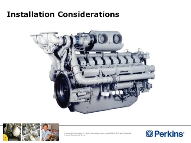
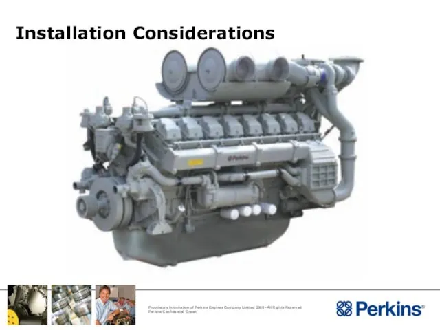
- 3. Installation Considerations
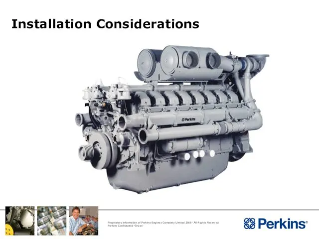
- 4. Installation Considerations
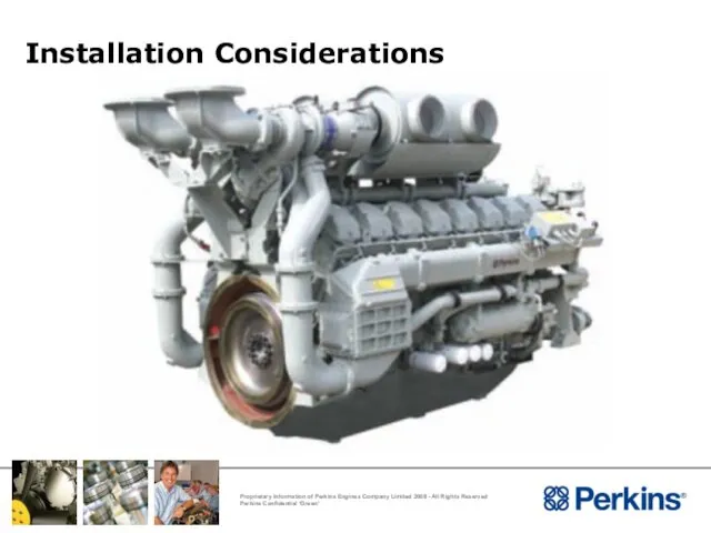
- 5. Installation Considerations
- 6. Installation Considerations
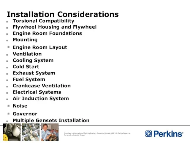
- 7. Installation Considerations Torsional Compatibility Flywheel Housing and Flywheel Engine Room Foundations Mounting Engine Room Layout Ventilation
- 8. Installation Considerations Torsional Compatibility
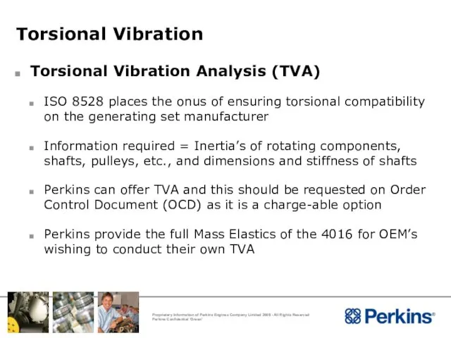
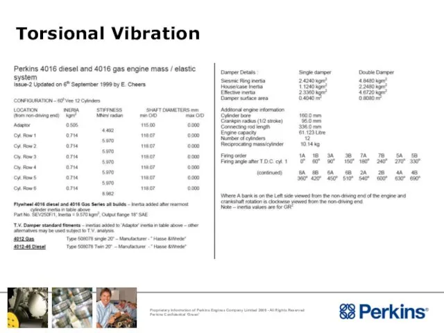
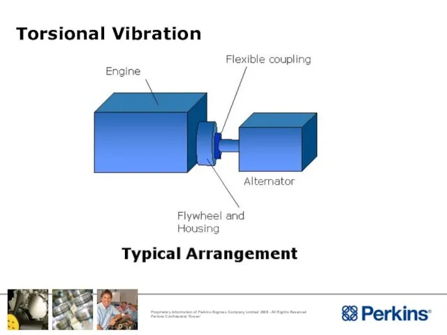
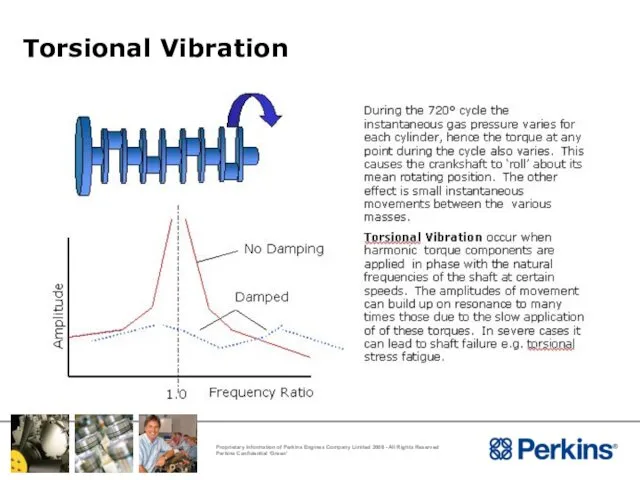
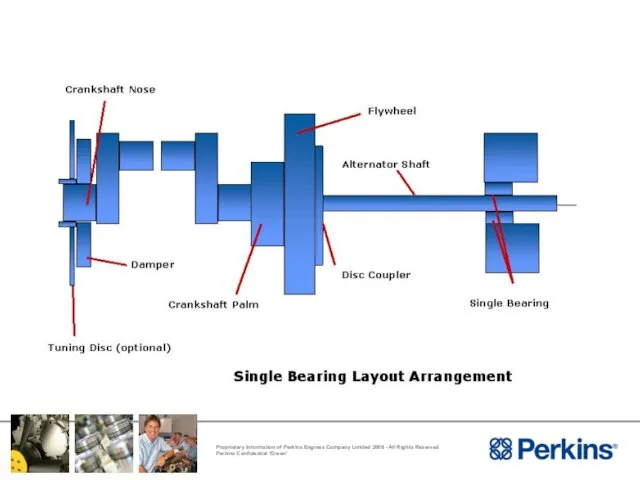
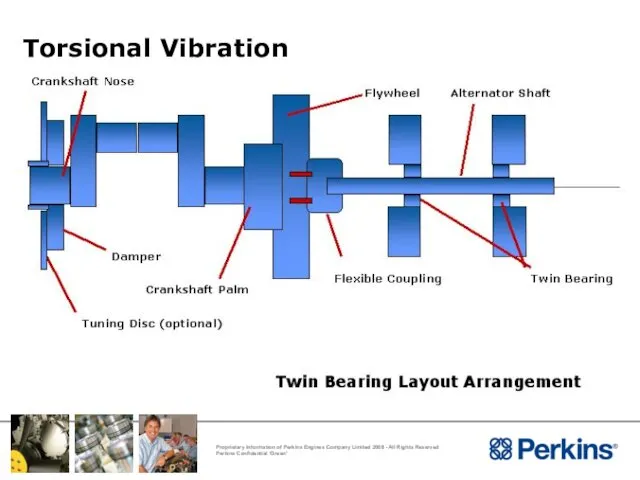
- 9. Torsional Vibration Torsional Vibration Analysis (TVA) ISO 8528 places the onus of ensuring torsional compatibility on
- 10. Torsional Vibration
- 11. Torsional Vibration
- 12. Torsional Vibration
- 14. Torsional Vibration
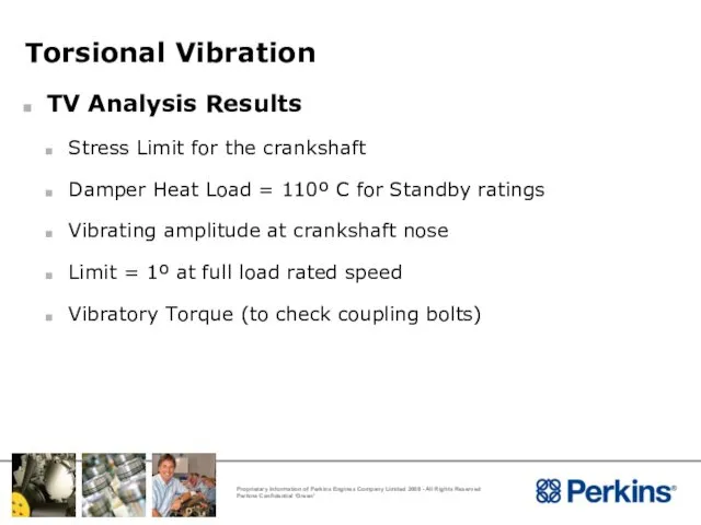
- 15. Torsional Vibration TV Analysis Results Stress Limit for the crankshaft Damper Heat Load = 110º C
- 16. TV Dampers
- 17. Applications Considerations Flywheel Housing and Flywheel
- 18. Flywheel Housing and Flywheel Flywheel Housing and Flywheel Size 4016 Supplied with : SAE J617 Size
- 19. Applications Considerations Engine Room Foundations
- 20. Engine Room Foundations Type of Foundation The engine floor/foundation where the underbase/bearers are fixed is of
- 21. Engine Room Foundations Subsoil - Site The site subsoil must have a bearing strength capable of
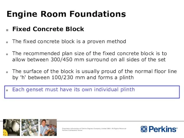
- 22. Engine Room Foundations Fixed Concrete Block The fixed concrete block is a proven method The recommended
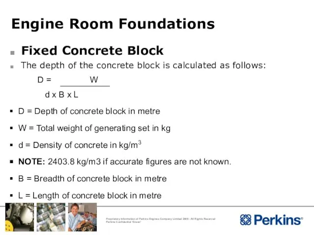
- 23. Engine Room Foundations Fixed Concrete Block The depth of the concrete block is calculated as follows:
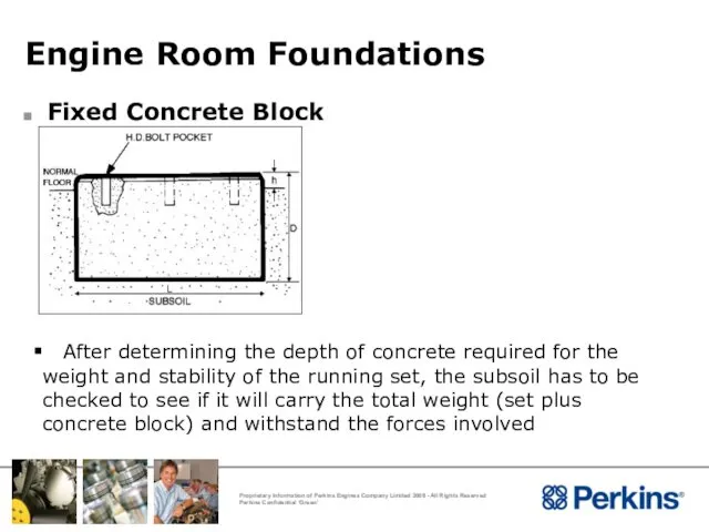
- 24. Engine Room Foundations Fixed Concrete Block After determining the depth of concrete required for the weight
- 25. Installation Considerations Engine Mounting
- 26. Mounting Systems Purpose Of Mounting Systems To secure the engine into the installation Provide adequate support
- 27. Mounting Systems Engine Mountings The type of mountings depend upon the type of installation in which
- 28. Mounting System Types Of Mounting Systems Flexible Mounting Systems Solid Mounting System
- 29. Mounting Systems Types Of Mounting Systems - Flexible Flexible mounting enable the supporting baseframe to be
- 30. Mounting Systems
- 31. Mounting Systems
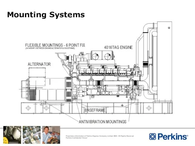
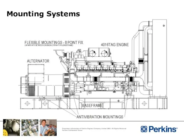
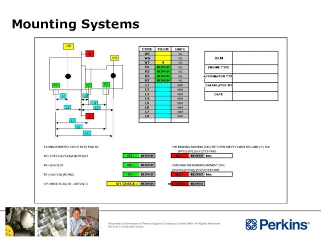
- 32. Mounting Systems Location of Mounts With flexible mounting the location of the mounts are predetermined by
- 33. Mounting Systems
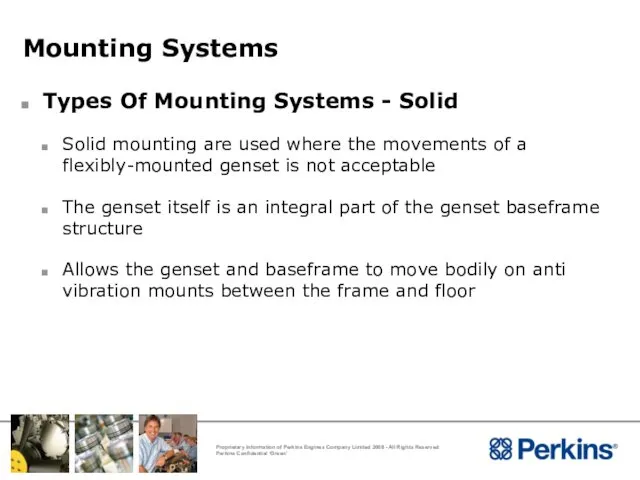
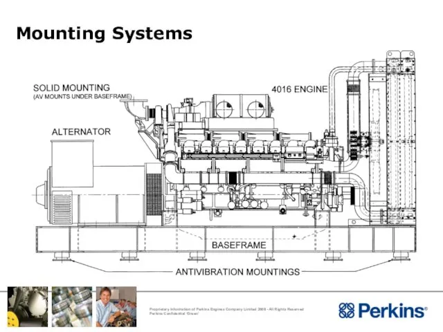
- 34. Mounting Systems Types Of Mounting Systems - Solid Solid mounting are used where the movements of
- 35. Mounting Systems
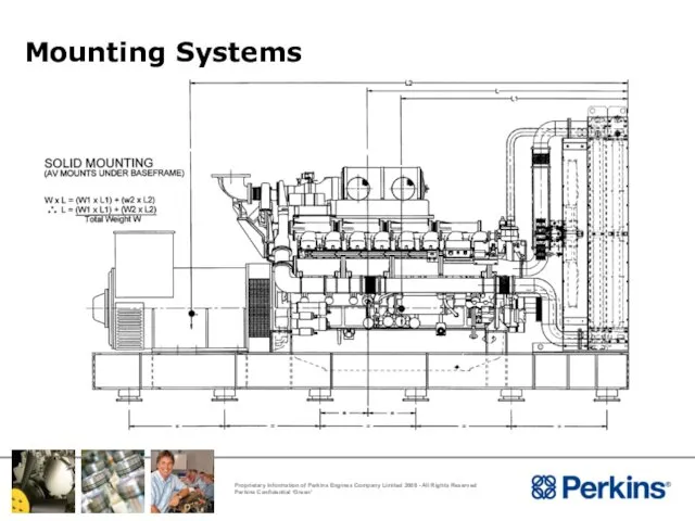
- 36. Mounting Systems Locations Of Mounts With solid mounting the anti vibration mounts should be symmetrically arranged
- 37. Mounting Systems
- 38. Mounting Systems General Considerations No restraints from exhaust pipes, hoses, linkages, etc Are the mounts fitted
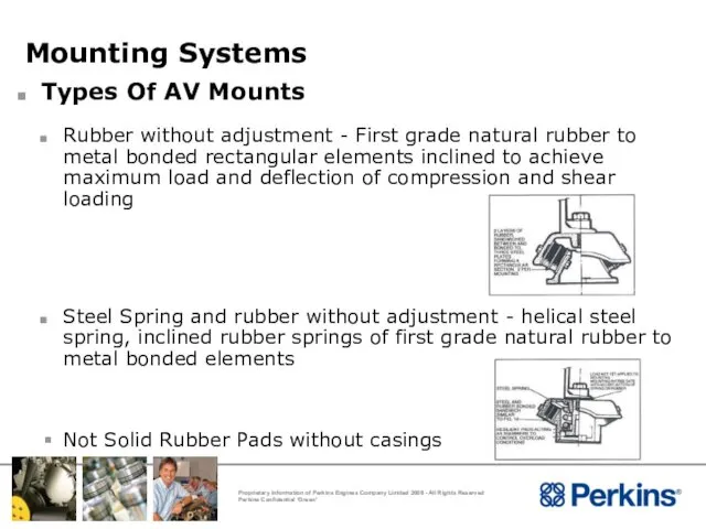
- 39. Mounting Systems Types Of AV Mounts Rubber without adjustment - First grade natural rubber to metal
- 40. Applications Considerations Engine Room layout
- 41. Engine Room Layout Access for Routine Servicing Installation and removal of various components : Cylinder heads
- 42. Engine Room Layout Access for Routine Servicing Maintenance, inspection and replacement of parts : Lubricating oil
- 43. Engine Room Layout Installation Guide lines Avoid plastic and other unsuitable material for fuel piping and
- 44. Engine Room Layout Typical Engine Room Layout Hot air from the radiator ducted outside the engine
- 45. Engine Room Layout
- 46. Installation Considerations Ventilation
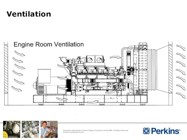
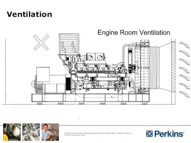
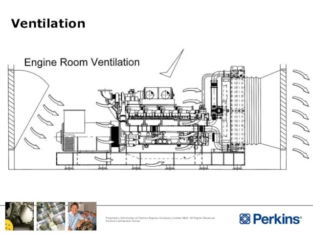
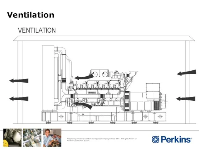
- 47. Ventilation Ventilation Basic principal is to extract hot air from the room and induce air at
- 48. Ventilation
- 49. Ventilation
- 50. Ventilation
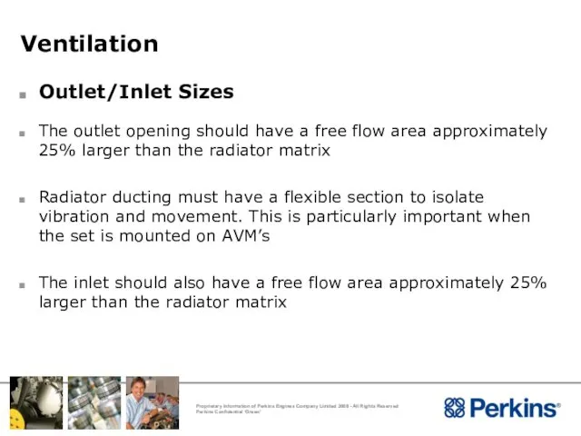
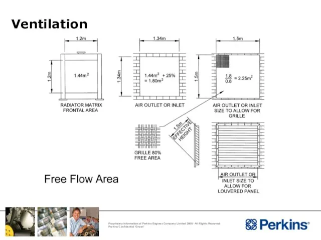
- 51. Ventilation Outlet/Inlet Sizes The outlet opening should have a free flow area approximately 25% larger than
- 52. Ventilation
- 53. Ventilation Extract from Institute of Heating & Ventilation Engineers Guide & Wood Practical Guide to Fan
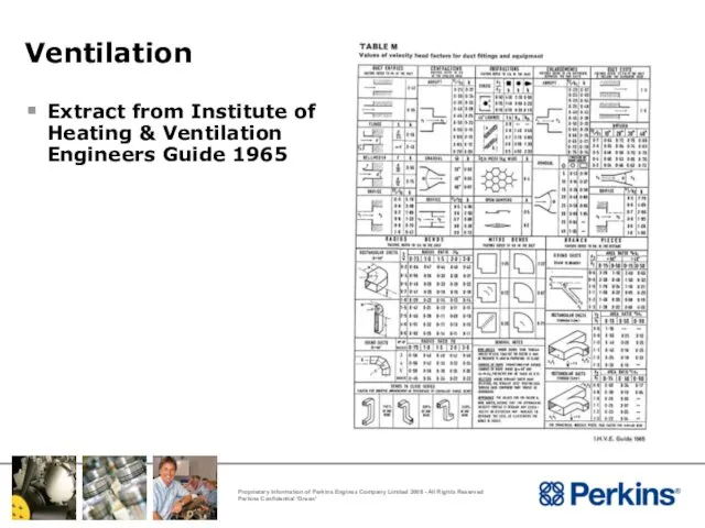
- 54. Ventilation Extract from Institute of Heating & Ventilation Engineers Guide 1965
- 55. Ventilation Duct Resistance Radiator duct allowance must not be exceeded. Exceeding the duct allowance can cause
- 56. PROCEDURE The anemometer measurement should be taken with the engine running at constant speed and no
- 57. Ventilation Continuous Traverse Carry out a moving traverse over the radiator face (averaging anemometer) To do
- 58. Ventilation Spot Measurements Spot measurements (single reading anemometer) This method assumes an anemometer capable of taking
- 59. Calculation of results The measured values from either method can then be input to a spreadsheet
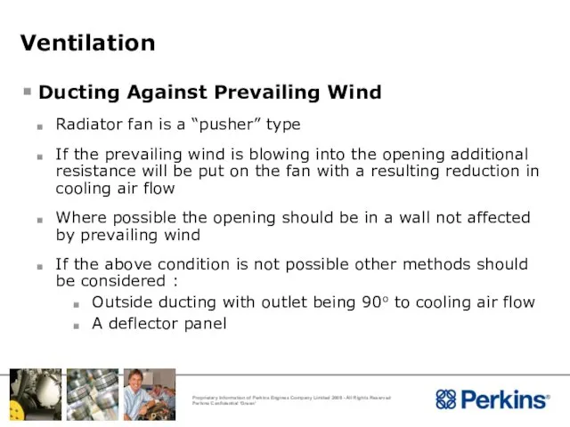
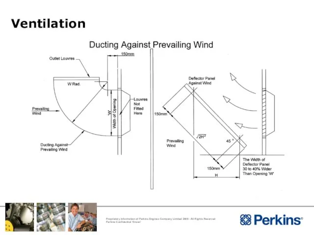
- 60. Ventilation Ducting Against Prevailing Wind Radiator fan is a “pusher” type If the prevailing wind is
- 61. Ventilation
- 62. Ventilation Ventilation – Tropical Conditions To cater for tropical conditions common practice is for the engine
- 63. Ventilation
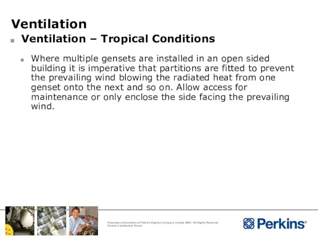
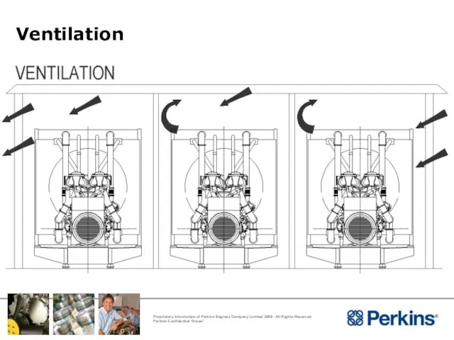
- 64. Ventilation Ventilation – Tropical Conditions Where multiple gensets are installed in an open sided building it
- 65. Ventilation
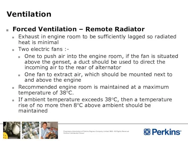
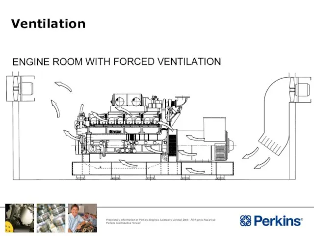
- 66. Ventilation Forced Ventilation – Remote Radiator Exhaust in engine room to be sufficiently lagged so radiated
- 67. Ventilation
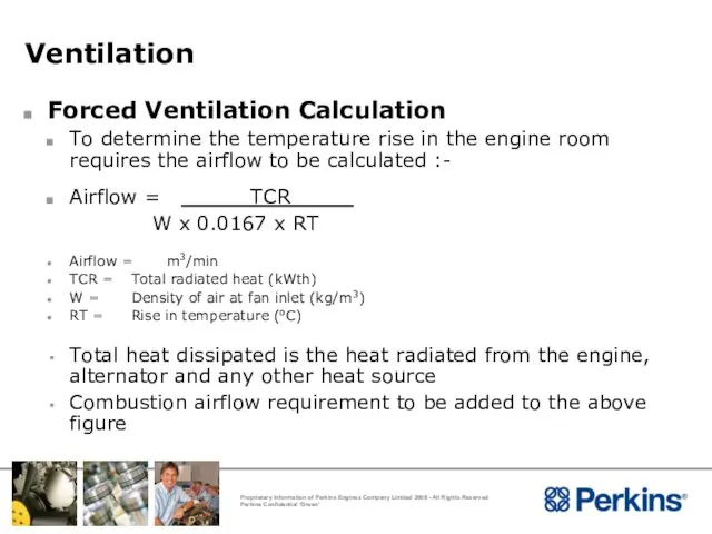
- 68. Ventilation Forced Ventilation Calculation To determine the temperature rise in the engine room requires the airflow
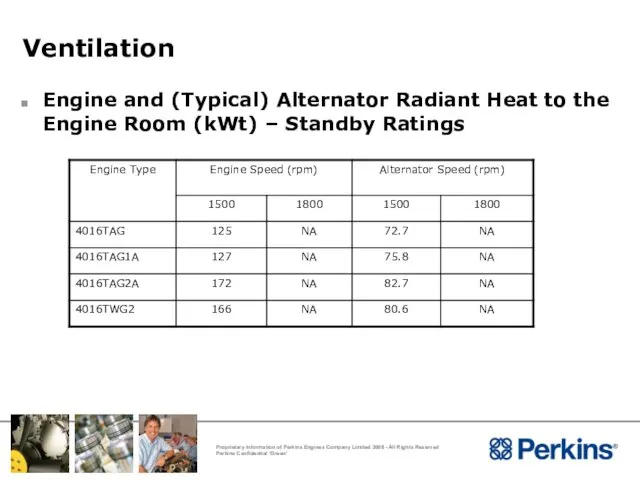
- 69. Ventilation Engine and (Typical) Alternator Radiant Heat to the Engine Room (kWt) – Standby Ratings
- 70. Installation Considerations Exhaust System
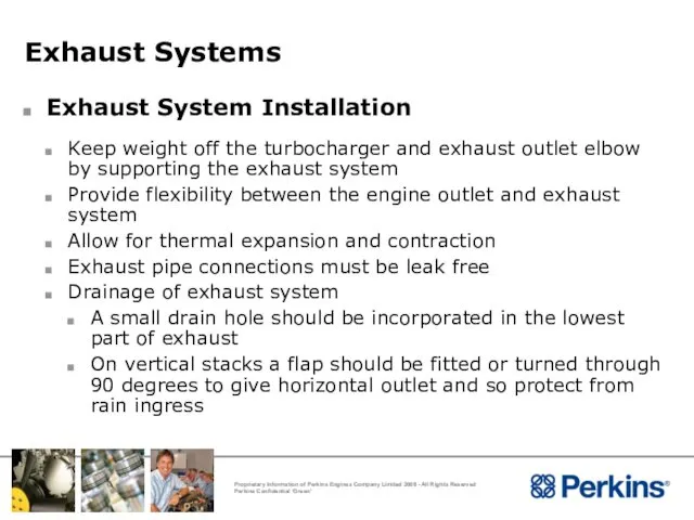
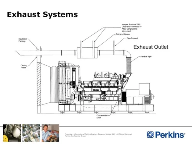
- 71. Exhaust Systems Exhaust System Installation Keep weight off the turbocharger and exhaust outlet elbow by supporting
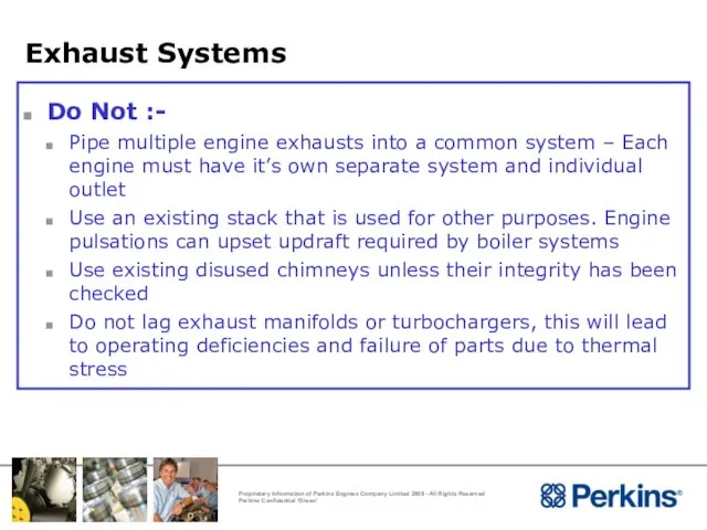
- 72. Exhaust Systems Do Not :- Pipe multiple engine exhausts into a common system – Each engine
- 73. Exhaust Systems
- 74. Exhaust Systems
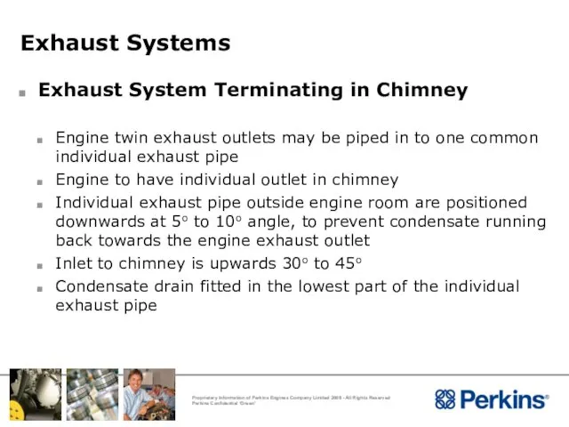
- 75. Exhaust Systems Exhaust System Terminating in Chimney Engine twin exhaust outlets may be piped in to
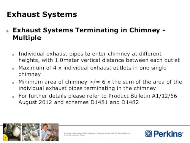
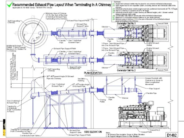
- 76. Exhaust Systems Exhaust Systems Terminating in Chimney - Multiple Individual exhaust pipes to enter chimney at
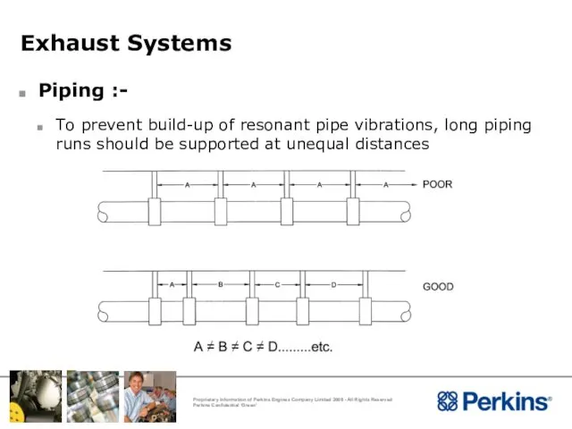
- 79. Exhaust Systems Piping :- To prevent build-up of resonant pipe vibrations, long piping runs should be
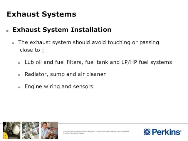
- 80. Exhaust Systems Exhaust System Installation The exhaust system should avoid touching or passing close to ;
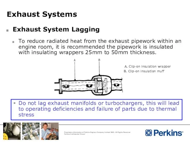
- 81. Exhaust Systems Exhaust System Lagging To reduce radiated heat from the exhaust pipework within an engine
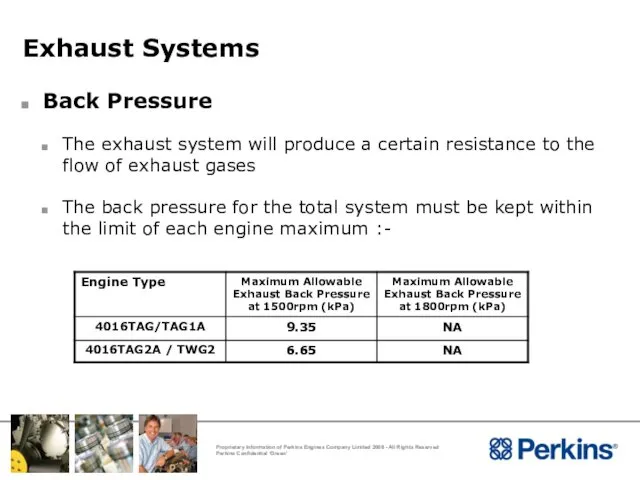
- 82. Exhaust Systems Back Pressure The exhaust system will produce a certain resistance to the flow of
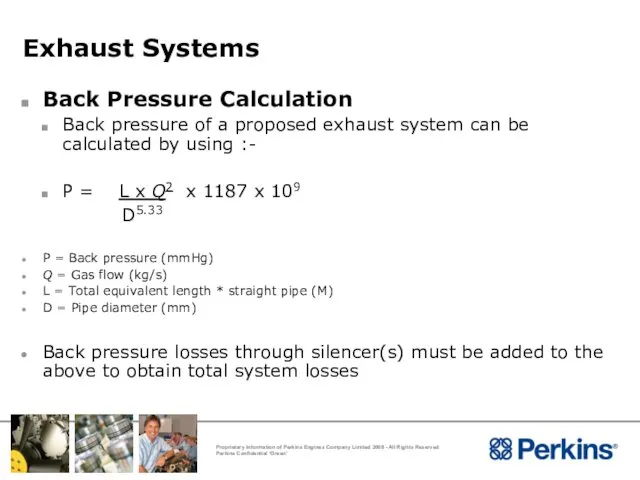
- 83. Exhaust Systems Back Pressure Calculation Back pressure of a proposed exhaust system can be calculated by
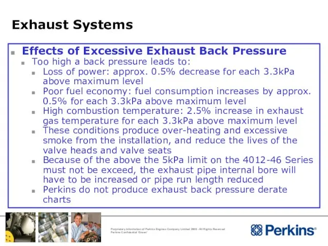
- 84. Exhaust Systems Effects of Excessive Exhaust Back Pressure Too high a back pressure leads to: Loss
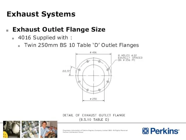
- 85. Exhaust Systems Exhaust Outlet Flange Size 4016 Supplied with : Twin 250mm BS 10 Table ‘D’
- 86. Installation Considerations The Cooling System
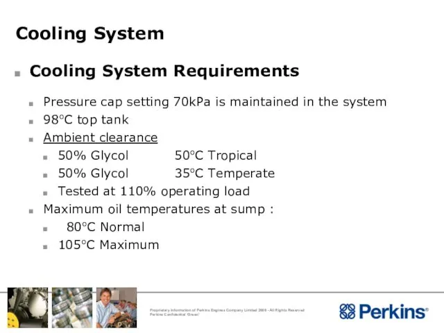
- 87. Cooling System Cooling System Requirements Pressure cap setting 70kPa is maintained in the system 98oC top
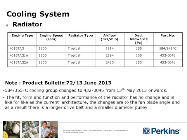
- 88. Cooling System Radiator Note : Product Bulletin 72/13 June 2013 584/365FC cooling group changed to 432-0046
- 89. Cooling System Radiator Construction Fin and tube Pusher fan Mounting Solid direct to baseframe
- 90. Cooling System Air To Air Charge Cooler Reduces induction air temperature Air to air radiator in
- 91. Cooling System TAG - Radiator Cooled A Air cleaner B Air cooled charge air cooler C
- 92. Cooling Systems
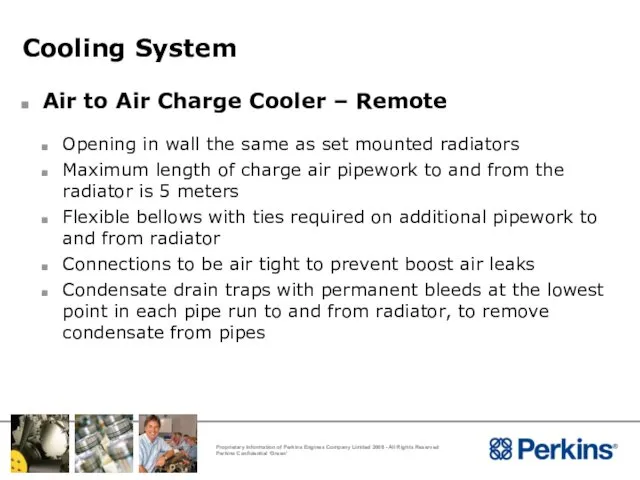
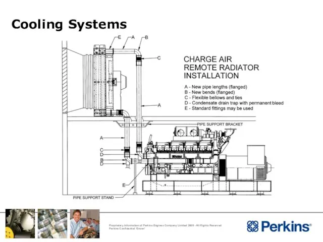
- 93. Cooling System Air to Air Charge Cooler – Remote Opening in wall the same as set
- 94. Cooling Systems
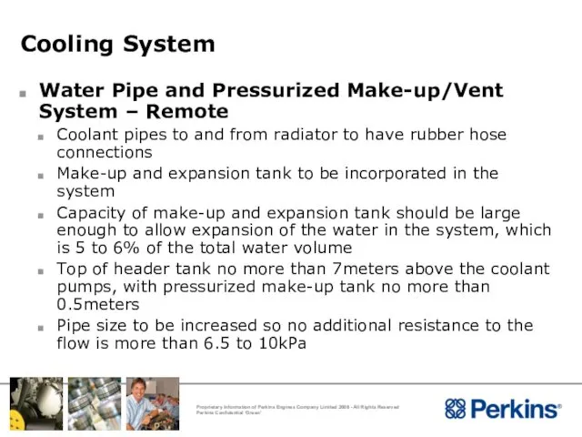
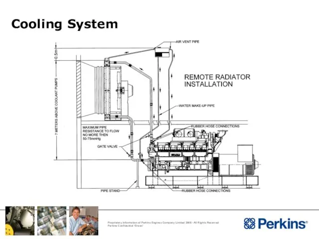
- 95. Cooling System Water Pipe and Pressurized Make-up/Vent System – Remote Coolant pipes to and from radiator
- 96. Cooling System
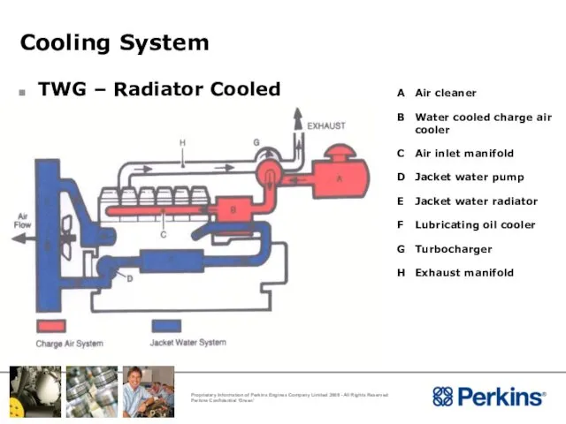
- 97. Cooling System TWG – Radiator Cooled A Air cleaner B Water cooled charge air cooler C
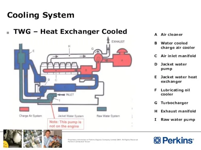
- 98. Cooling System TWG – Heat Exchanger Cooled A Air cleaner B Water cooled charge air cooler
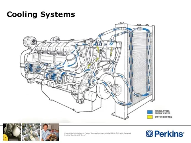
- 99. Cooling Systems
- 100. Cooling System Protection Antifreeze 50% mixture Inhibited ethylene glycol or inhibited propylene glycol Corrosion Inhibitor –
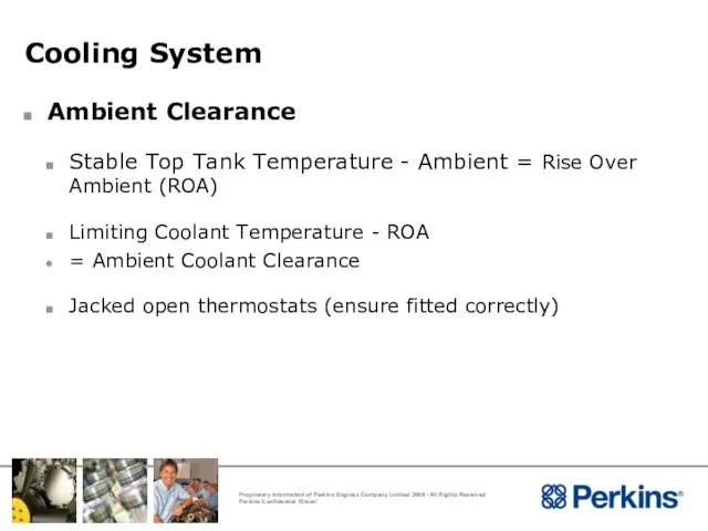
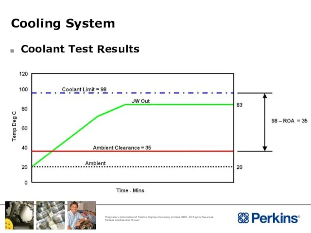
- 101. Cooling System Ambient Clearance Stable Top Tank Temperature - Ambient = Rise Over Ambient (ROA) Limiting
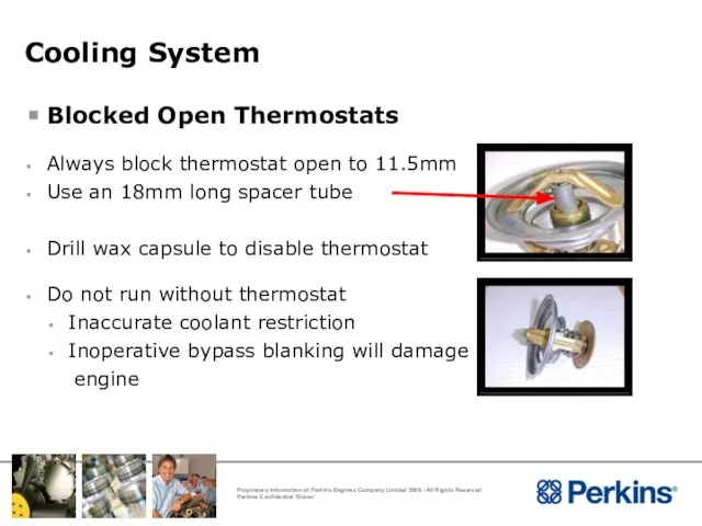
- 102. Cooling System Blocked Open Thermostats Always block thermostat open to 11.5mm Use an 18mm long spacer
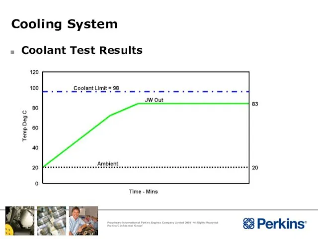
- 103. Cooling System Coolant Test Results
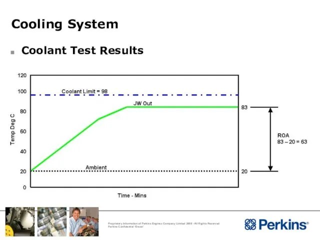
- 104. Cooling System Coolant Test Results
- 105. Cooling System Coolant Test Results
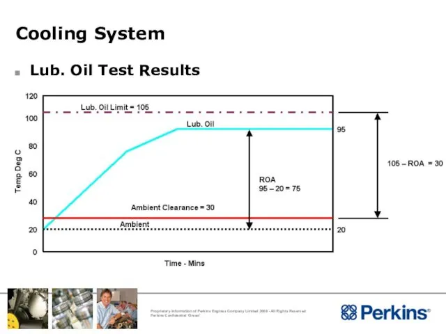
- 106. Cooling System Lub. Oil Test Results
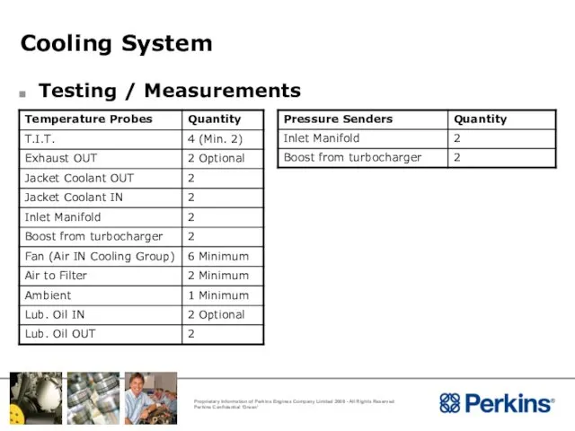
- 107. Cooling System Testing / Measurements
- 108. Cooling System Analysis Of Results Low coolant clearance Excessive duct restriction Re-circulation
- 109. Cooling System De-Aeration Possible Causes Poor filling Poor venting Blockages
- 110. Cooling System De-Aeration Effects of air in water Local boiling Excessive coolant loss Deterioration of water
- 111. Applications Considerations Cold Start
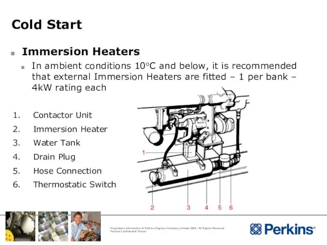
- 112. Cold Start Immersion Heaters In ambient conditions 10oC and below, it is recommended that external Immersion
- 113. Installation Considerations Fuel System
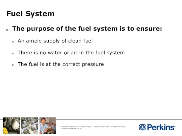
- 114. Fuel System The purpose of the fuel system is to ensure: An ample supply of clean
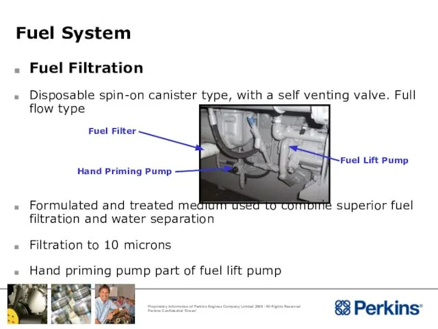
- 115. Fuel System Fuel Filtration Disposable spin-on canister type, with a self venting valve. Full flow type
- 116. Fuel System
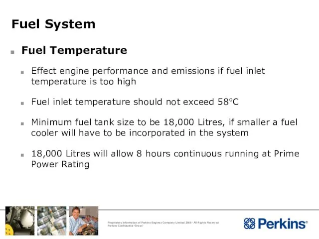
- 117. Fuel System Fuel Temperature Effect engine performance and emissions if fuel inlet temperature is too high
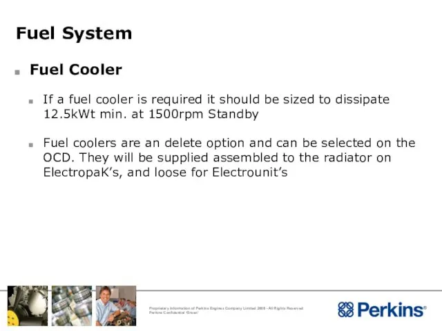
- 118. Fuel System Fuel Cooler If a fuel cooler is required it should be sized to dissipate
- 119. Fuel System
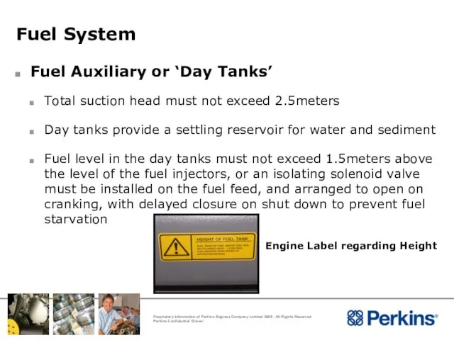
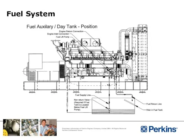
- 120. Fuel System Fuel Auxiliary or ‘Day Tanks’ Total suction head must not exceed 2.5meters Day tanks
- 121. Fuel System
- 122. Fuel System
- 123. Fuel System Fuel Auxiliary or ‘Day Tanks’ Weirs must be incorporated in the day tank to
- 124. Fuel System
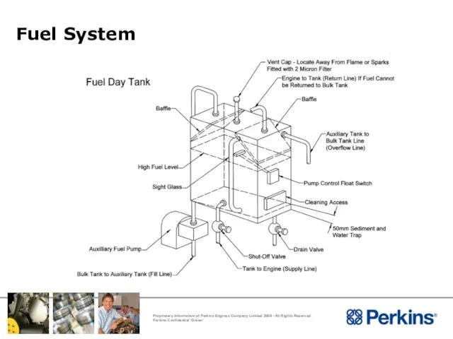
- 125. Fuel System Fuel Tank The fuel intake pipe must be above the bottom of the tank
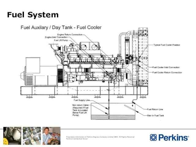
- 126. Fuel System Bulk and Day Tank System
- 127. Fuel System Low Pressure Fuel Pipes Material - Good quality seamless copper pipe, steel or black
- 128. Fuel System Water Trap and Sedimenter A water trap and sedimenter should be installed into all
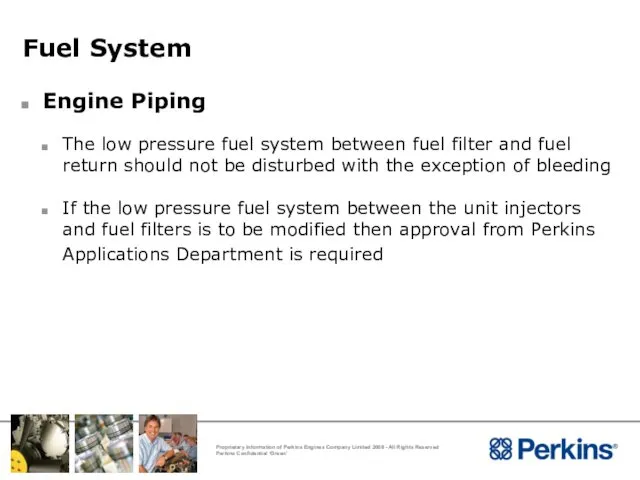
- 129. Fuel System Engine Piping The low pressure fuel system between fuel filter and fuel return should
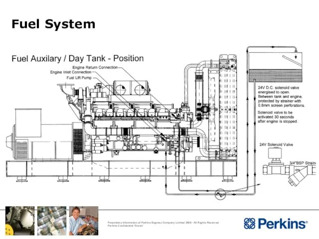
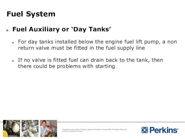
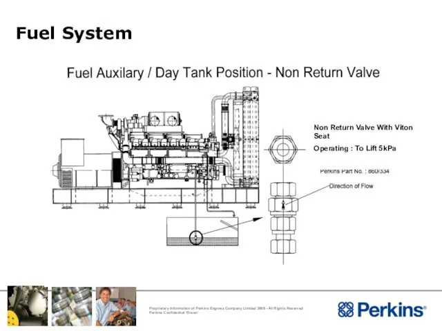
- 130. Fuel System Fuel Auxiliary or ‘Day Tanks’ For day tanks installed below the engine fuel lift
- 131. Fuel System
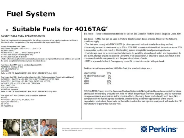
- 132. Fuel System Suitable Fuels for 4016TAG’
- 133. Installation Considerations Lubricating Oil System
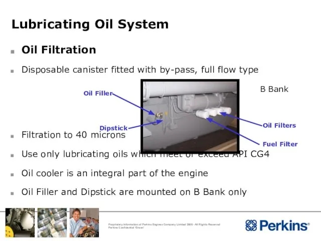
- 134. Lubricating Oil System Oil Filtration Disposable canister fitted with by-pass, full flow type Filtration to 40
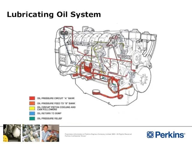
- 135. Lubricating Oil System
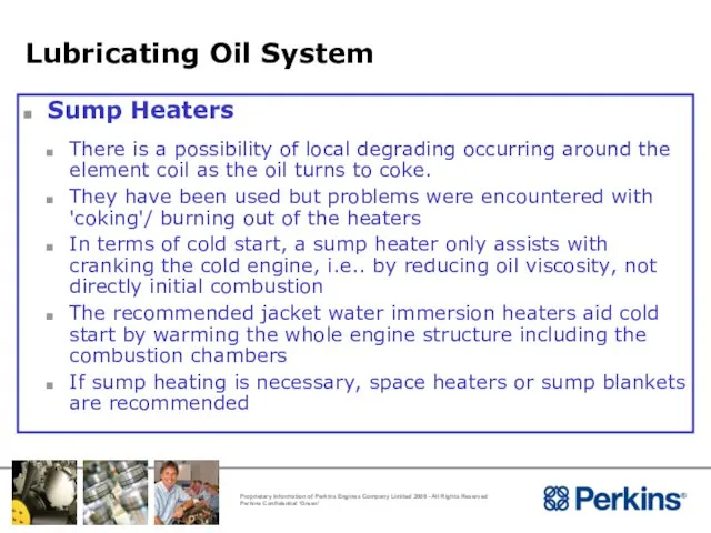
- 136. Lubricating Oil System Sump Heaters There is a possibility of local degrading occurring around the element
- 137. Installation Considerations Crankcase Ventilation
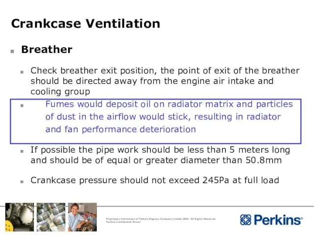
- 138. Crankcase Ventilation Breather Check breather exit position, the point of exit of the breather should be
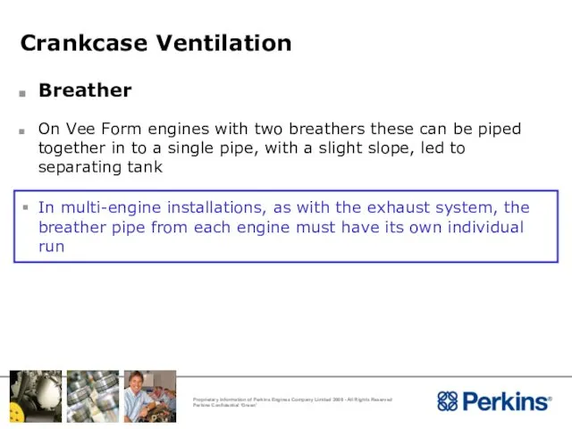
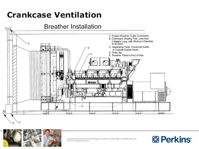
- 139. Crankcase Ventilation Breather On Vee Form engines with two breathers these can be piped together in
- 140. Crankcase Ventilation
- 141. Installation Considerations Electrical Systems
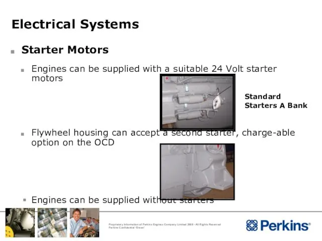
- 142. Electrical Systems Starter Motors Engines can be supplied with a suitable 24 Volt starter motors Flywheel
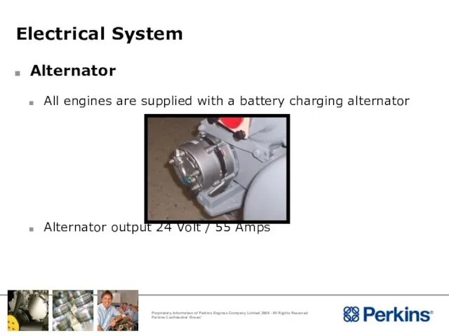
- 143. Electrical System Alternator All engines are supplied with a battery charging alternator Alternator output 24 Volt
- 144. Electrical System Batteries There are three main types of battery in circulation these are : Ni-Cad
- 145. Electrical System Good Wiring Practice Ensure suitable cables have been used Where possible cables should be
- 146. Electrical System
- 147. Electrical Systems Protection Devices 4016 are fitted with the following shut-down protection as standard : High
- 148. Electrical Systems High Jacket Water Switch (HJW) Set to 101 o C (Rising) A + B
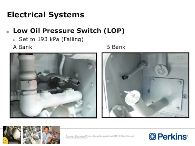
- 149. Electrical Systems Low Oil Pressure Switch (LOP) Set to 193 kPa (Falling) A Bank B Bank
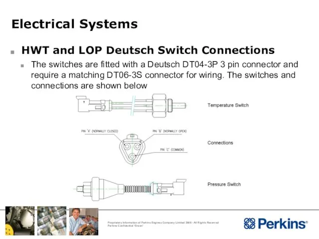
- 150. Electrical Systems HWT and LOP Deutsch Switch Connections The switches are fitted with a Deutsch DT04-3P
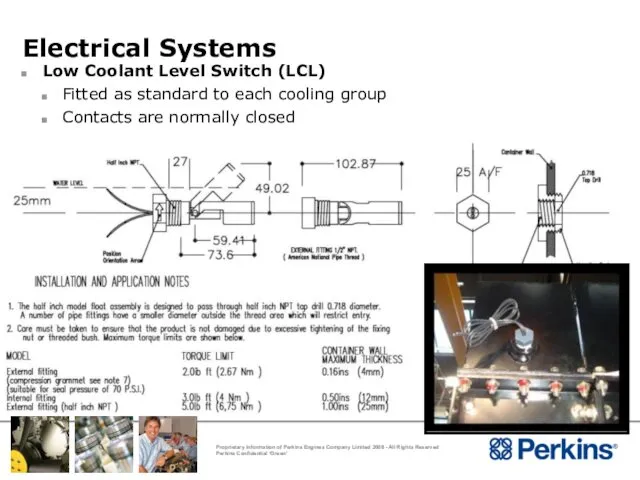
- 151. Electrical Systems Low Coolant Level Switch (LCL) Fitted as standard to each cooling group Contacts are
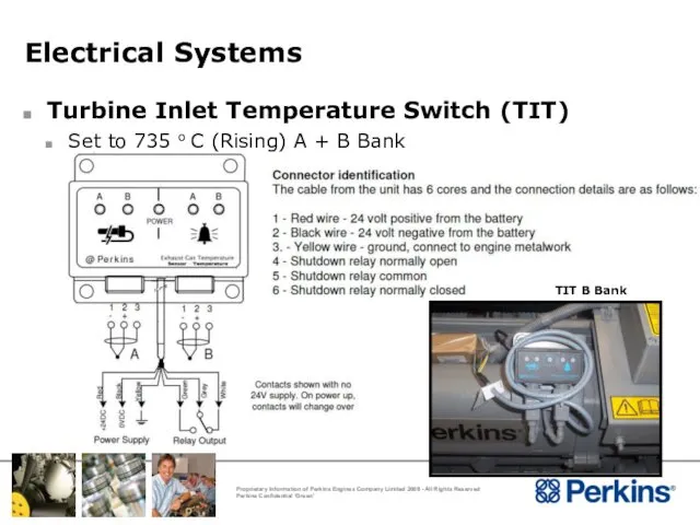
- 152. Electrical Systems Turbine Inlet Temperature Switch (TIT) Set to 735 o C (Rising) A + B
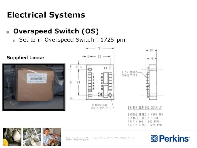
- 153. Electrical Systems Overspeed Switch (OS) Set to in Overspeed Switch : 1725rpm Supplied Loose
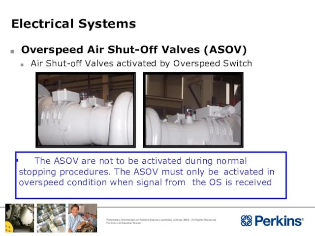
- 154. Electrical Systems Overspeed Air Shut-Off Valves (ASOV) Air Shut-off Valves activated by Overspeed Switch The ASOV
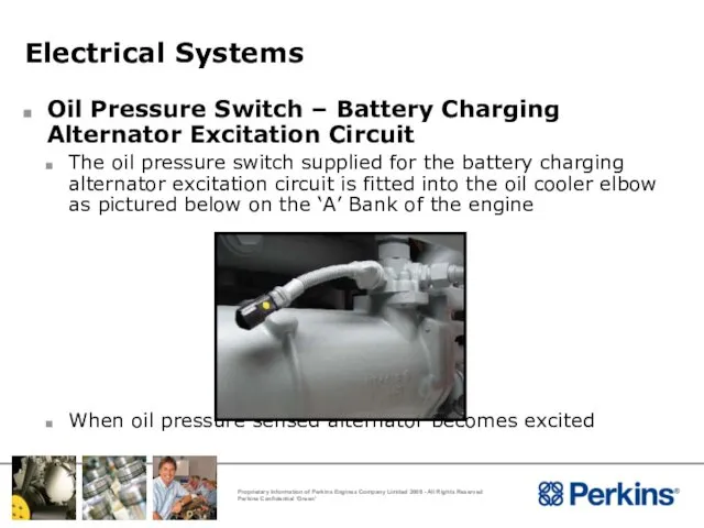
- 155. Electrical Systems Oil Pressure Switch – Battery Charging Alternator Excitation Circuit The oil pressure switch supplied
- 156. Applications Considerations Air Induction System
- 157. Air Induction System Engine Mounted Air Filters Medium Duty paper element type Filtration 98% of all
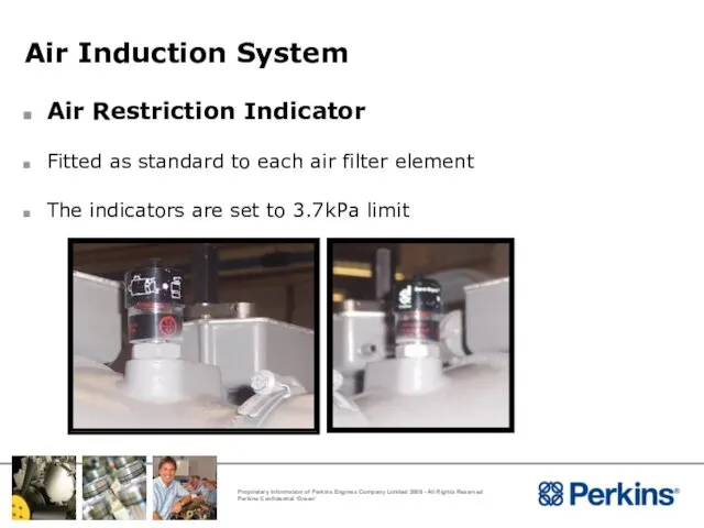
- 158. Air Induction System Air Restriction Indicator Fitted as standard to each air filter element The indicators
- 159. Air Induction System Oil Bath Air Filters Perkins do not recommend the use of oil bath
- 160. Air Induction System Oil Bath Air Filters Another potentially disastrous problem is that the oil bath
- 161. Installation Considerations Noise Control
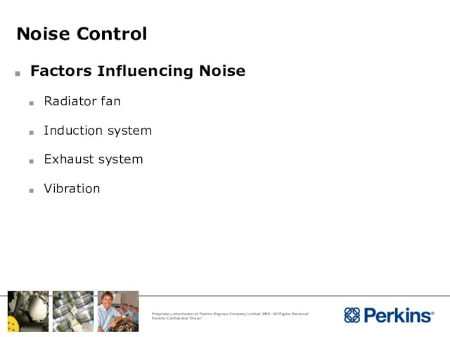
- 162. Noise Control Factors Influencing Noise Radiator fan Induction system Exhaust system Vibration
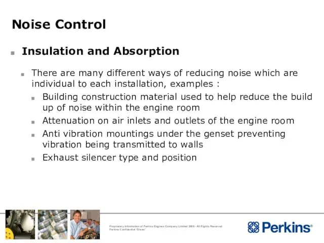
- 163. Noise Control Insulation and Absorption There are many different ways of reducing noise which are individual
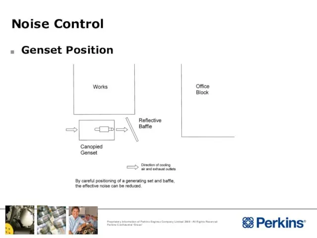
- 164. Noise Control Genset Position
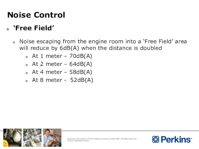
- 165. Noise Control ‘Free Field’ Noise escaping from the engine room into a ‘Free Field’ area will
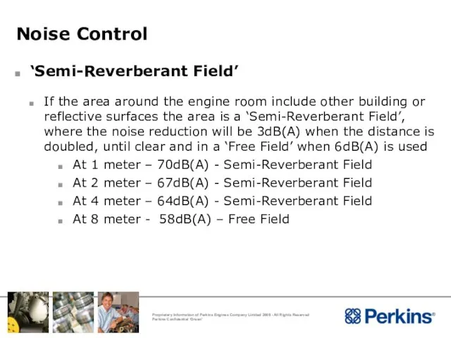
- 166. Noise Control ‘Semi-Reverberant Field’ If the area around the engine room include other building or reflective
- 167. Installation Considerations Governing
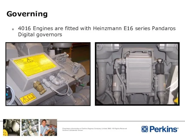
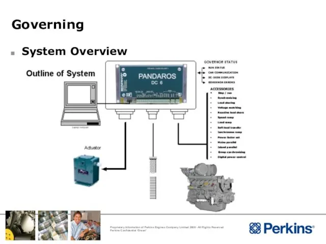
- 168. Governing 4016 Engines are fitted with Heinzmann E16 series Pandaros Digital governors
- 169. Governing System Overview
- 170. Governing Configuration The engine will be configured are shown below: Speed 1500rpm or 1800rpm Droop /
- 171. Governing Changing the configuration of the governor In order to change the configuration of the engine
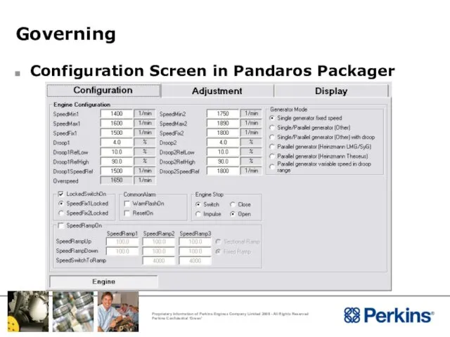
- 172. Governing Configuration Screen in Pandaros Packager
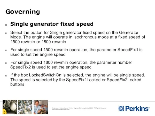
- 173. Governing Single generator fixed speed Select the button for Single generator fixed speed on the Generator
- 174. Governing Parallel Generator to Heinzmann LSU/Sync When the Generator Mode - Parallel generator option is selected,
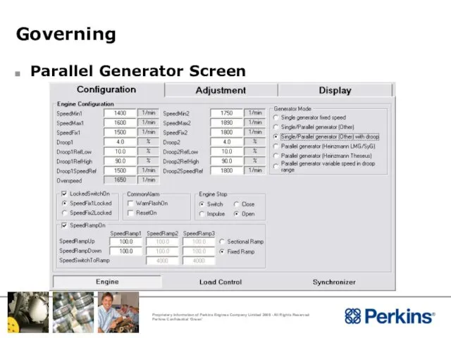
- 175. Governing Parallel Generator Screen
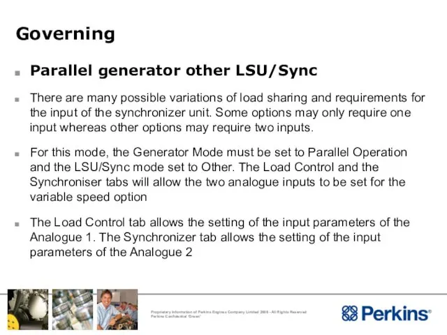
- 176. Governing Parallel generator other LSU/Sync There are many possible variations of load sharing and requirements for
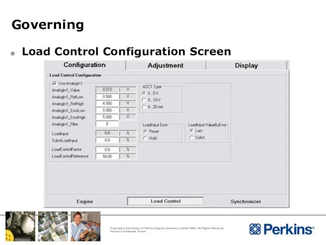
- 177. Governing Load Control Configuration Screen
- 178. Governing Parallel generator other LSU/Sync ADC 1_Type - The parameter enables the selection of the type
- 179. Governing Parallel generator other LSU/Sync AnalogIn1_ErrorLow - AnalogIn1_ErrorLow sets the lowest value at which analogue 1
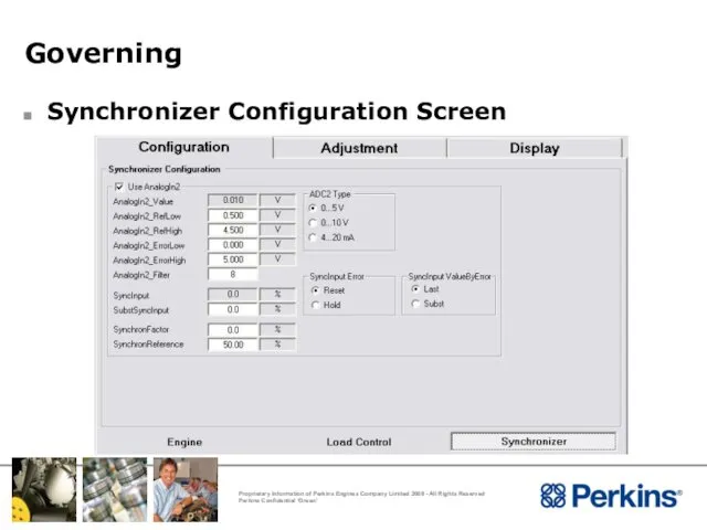
- 180. Governing Synchronizer Configuration Screen
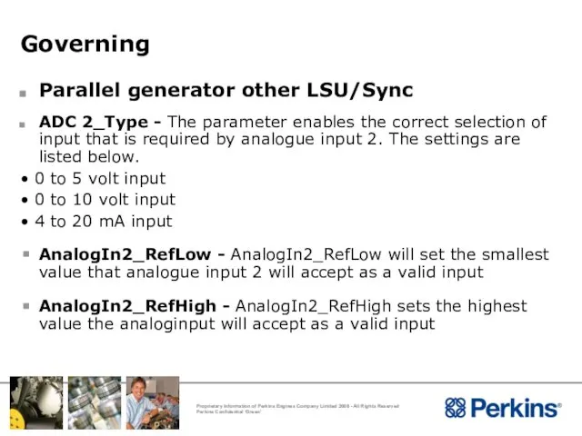
- 181. Governing Parallel generator other LSU/Sync ADC 2_Type - The parameter enables the correct selection of input
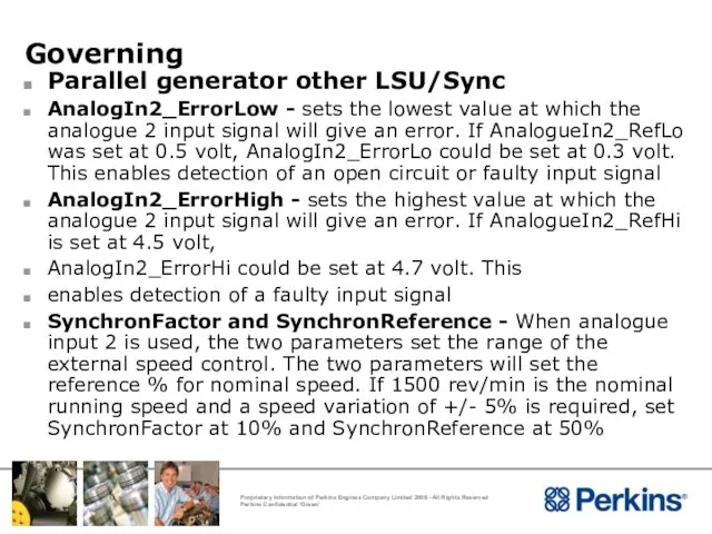
- 182. Governing Parallel generator other LSU/Sync AnalogIn2_ErrorLow - sets the lowest value at which the analogue 2
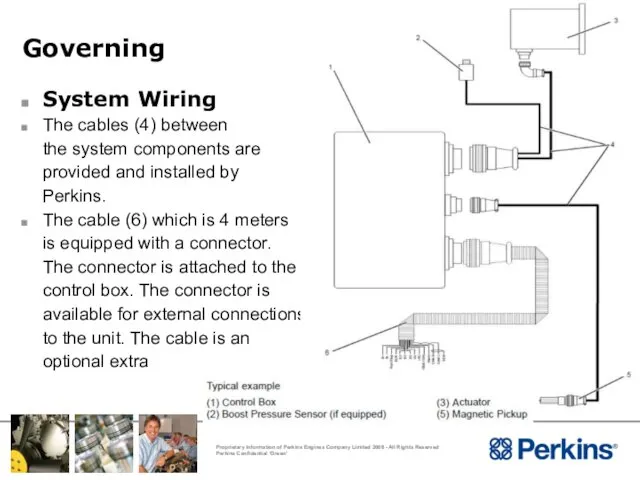
- 183. Governing System Wiring The cables (4) between the system components are provided and installed by Perkins.
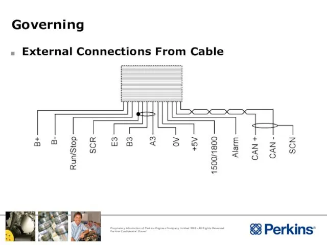
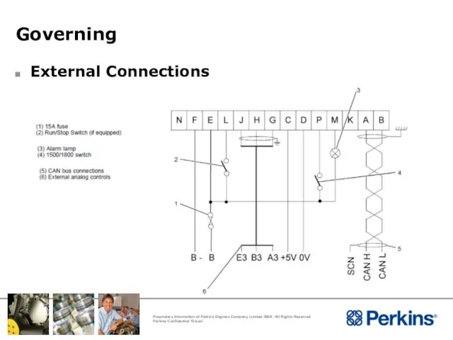
- 184. Governing External Connections From Cable
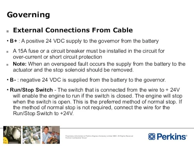
- 185. Governing External Connections From Cable • B+ : A positive 24 VDC supply to the governor
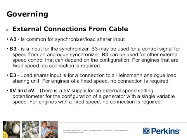
- 186. Governing External Connections From Cable • A3 - is common for synchronizer/load sharer input. • B3
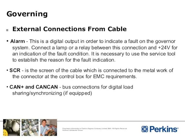
- 187. Governing External Connections From Cable • Alarm - This is a digital output in order to
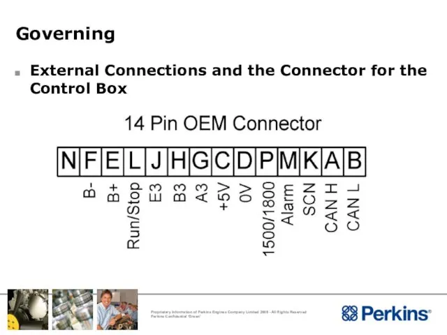
- 188. Governing External Connections and the Connector for the Control Box
- 189. Governing External Connections
- 190. Governing Cable Sizes The cables for the supply for the battery must be 1.5 square mm
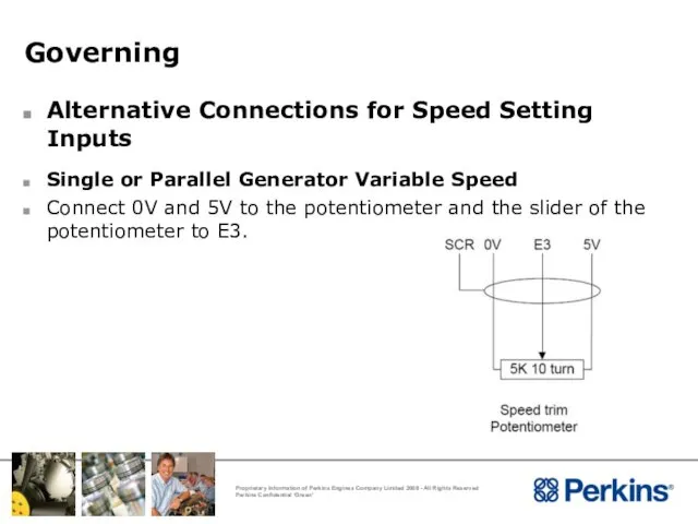
- 191. Governing Alternative Connections for Speed Setting Inputs Single or Parallel Generator Variable Speed Connect 0V and
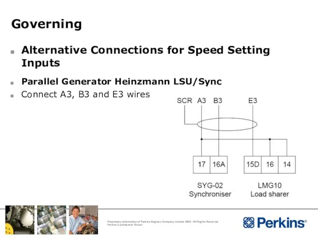
- 192. Governing Alternative Connections for Speed Setting Inputs Parallel Generator Heinzmann LSU/Sync Connect A3, B3 and E3
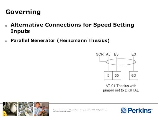
- 193. Governing Alternative Connections for Speed Setting Inputs Parallel Generator (Heinzmann Thesius)
- 194. Governing Governor Performance to ISO 3046 Part 4 4016 to ISO 8528-12 and G2 limits stated
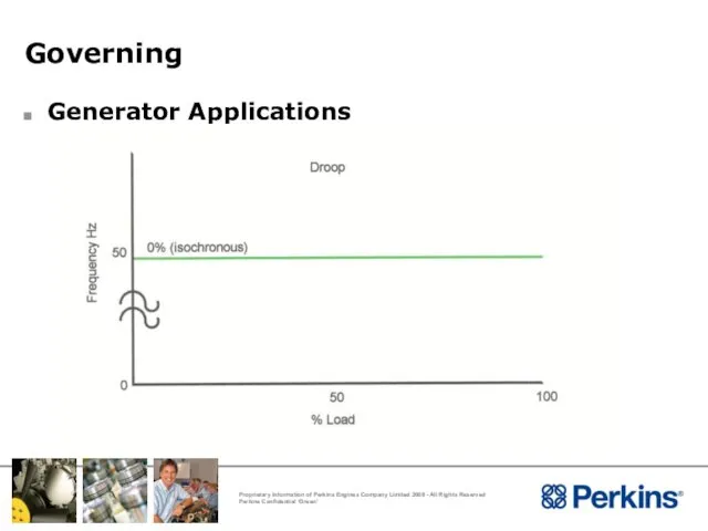
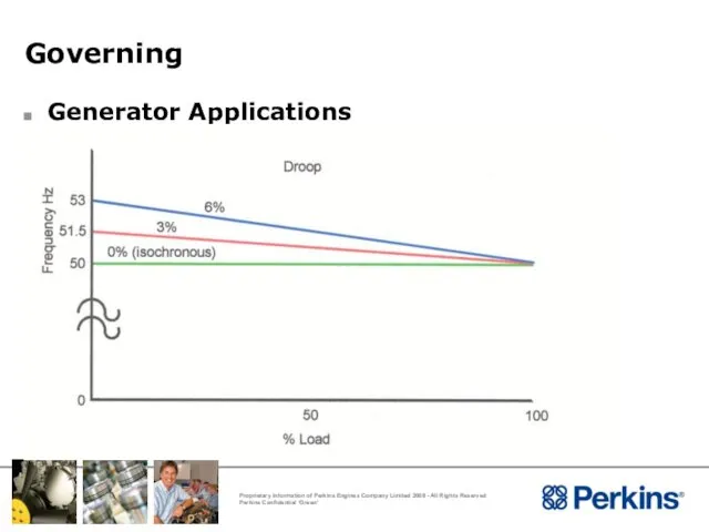
- 195. Governing Generator Applications
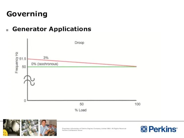
- 196. Governing Generator Applications
- 197. Governing Generator Applications
- 198. Installation Considerations Multiple Gensets Installation
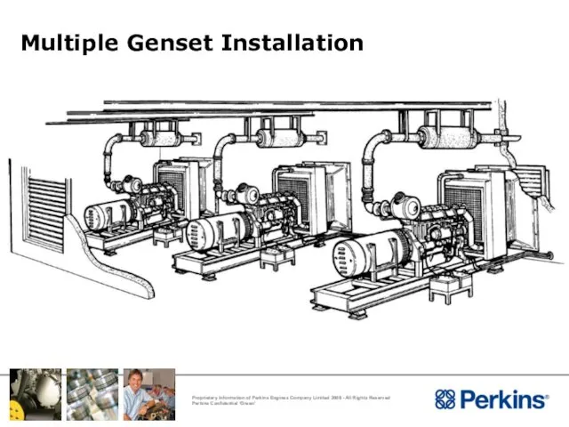
- 199. Multiple Genset Installation General – same guidelines as for single unit Each genset to have it’s
- 200. Multiple Genset Installation
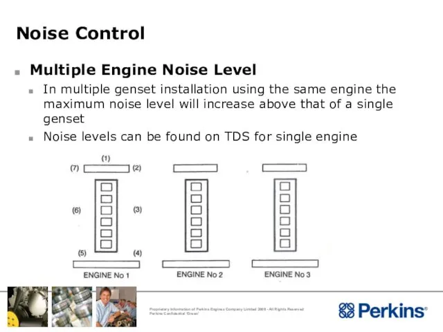
- 201. Noise Control Multiple Engine Noise Level In multiple genset installation using the same engine the maximum
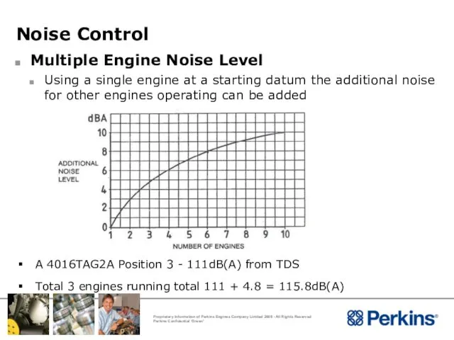
- 202. Noise Control Multiple Engine Noise Level Using a single engine at a starting datum the additional
- 203. Installation Considerations Data Available To Support Installations
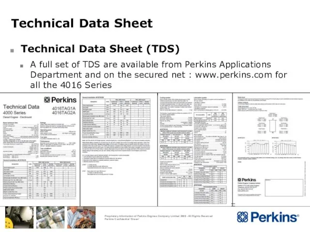
- 204. Technical Data Sheet Technical Data Sheet (TDS) A full set of TDS are available from Perkins
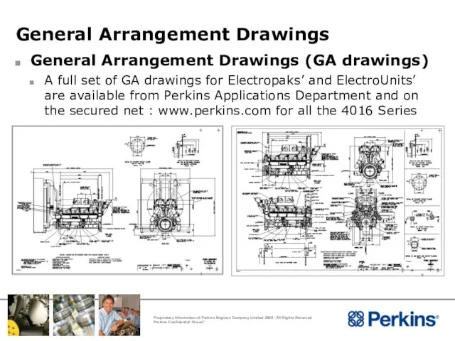
- 205. General Arrangement Drawings General Arrangement Drawings (GA drawings) A full set of GA drawings for Electropaks’
- 206. Derate Derate Derate means reducing the engines maximum power rating at normal temperatures and pressure conditions
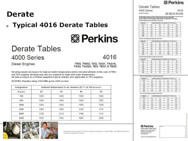
- 207. Derate Typical 4016 Derate Tables
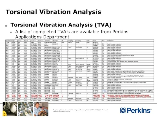
- 208. Torsional Vibration Analysis Torsional Vibration Analysis (TVA) A list of completed TVA’s are available from Perkins
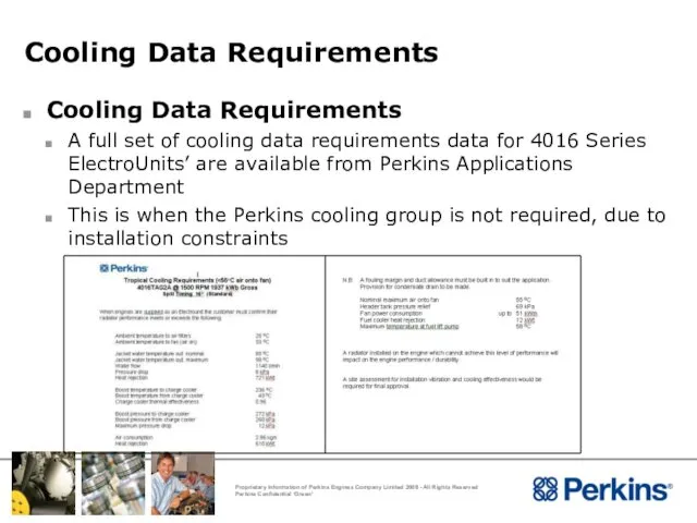
- 209. Cooling Data Requirements Cooling Data Requirements A full set of cooling data requirements data for 4016
- 211. Скачать презентацию
Application Considerations
Please Note :
This Product Training information is distributed for informational
Application Considerations
Please Note :
This Product Training information is distributed for informational
Installation Considerations
Installation Considerations
Installation Considerations
Installation Considerations
Installation Considerations
Installation Considerations
Installation Considerations
Installation Considerations
Installation Considerations
Torsional Compatibility
Flywheel Housing and Flywheel
Engine Room Foundations
Mounting
Engine Room Layout
Ventilation
Cooling System
Cold
Installation Considerations
Torsional Compatibility
Flywheel Housing and Flywheel
Engine Room Foundations
Mounting
Engine Room Layout
Ventilation
Cooling System
Cold
Installation Considerations
Torsional Compatibility
Installation Considerations
Torsional Compatibility
Torsional Vibration
Torsional Vibration Analysis (TVA)
ISO 8528 places the onus of ensuring
Torsional Vibration
Torsional Vibration Analysis (TVA)
ISO 8528 places the onus of ensuring
Torsional Vibration
Torsional Vibration
Torsional Vibration
Torsional Vibration
Torsional Vibration
Torsional Vibration
Torsional Vibration
Torsional Vibration
Torsional Vibration
TV Analysis Results
Stress Limit for the crankshaft
Damper Heat Load =
Torsional Vibration
TV Analysis Results
Stress Limit for the crankshaft
Damper Heat Load =
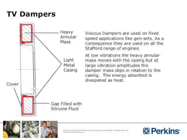
TV Dampers
TV Dampers
Applications Considerations
Flywheel Housing and Flywheel
Applications Considerations
Flywheel Housing and Flywheel
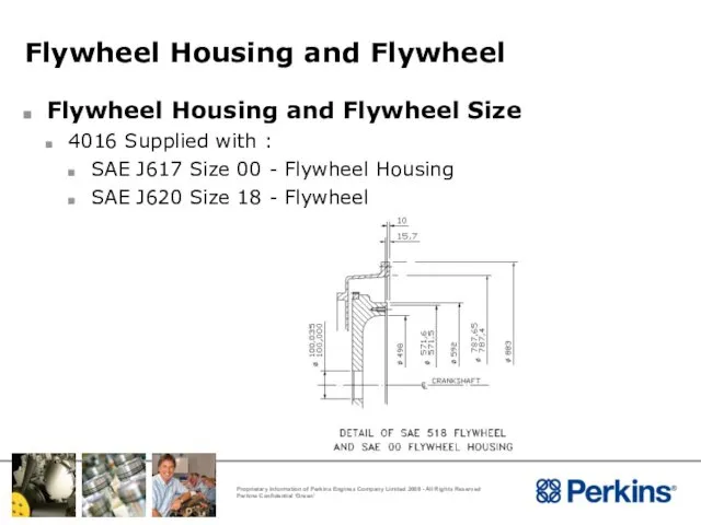
Flywheel Housing and Flywheel
Flywheel Housing and Flywheel Size
4016 Supplied with :
SAE
Flywheel Housing and Flywheel
Flywheel Housing and Flywheel Size
4016 Supplied with :
SAE
Applications Considerations
Engine Room Foundations
Applications Considerations
Engine Room Foundations
Engine Room Foundations
Type of Foundation
The engine floor/foundation where the underbase/bearers are
Engine Room Foundations
Type of Foundation
The engine floor/foundation where the underbase/bearers are
Engine Room Foundations
Subsoil - Site
The site subsoil must have a bearing
Engine Room Foundations
Subsoil - Site
The site subsoil must have a bearing
Engine Room Foundations
Fixed Concrete Block
The fixed concrete block is a proven
Engine Room Foundations
Fixed Concrete Block
The fixed concrete block is a proven
Engine Room Foundations
Fixed Concrete Block
The depth of the concrete block is
Engine Room Foundations
Fixed Concrete Block
The depth of the concrete block is
Engine Room Foundations
Fixed Concrete Block
After determining the depth of concrete
Engine Room Foundations
Fixed Concrete Block
After determining the depth of concrete
Installation Considerations
Engine Mounting
Installation Considerations
Engine Mounting
Mounting Systems
Purpose Of Mounting Systems
To secure the engine into the installation
Provide
Mounting Systems
Purpose Of Mounting Systems
To secure the engine into the installation
Provide
Mounting Systems
Engine Mountings
The type of mountings depend upon the type of
Mounting Systems
Engine Mountings
The type of mountings depend upon the type of
Mounting System
Types Of Mounting Systems
Flexible Mounting Systems
Solid Mounting System
Mounting System
Types Of Mounting Systems
Flexible Mounting Systems
Solid Mounting System
Mounting Systems
Types Of Mounting Systems - Flexible
Flexible mounting enable the supporting
Mounting Systems
Types Of Mounting Systems - Flexible
Flexible mounting enable the supporting
Mounting Systems
Mounting Systems
Mounting Systems
Mounting Systems
Mounting Systems
Location of Mounts
With flexible mounting the location of the mounts
Mounting Systems
Location of Mounts
With flexible mounting the location of the mounts
Mounting Systems
Mounting Systems
Mounting Systems
Types Of Mounting Systems - Solid
Solid mounting are used where
Mounting Systems
Types Of Mounting Systems - Solid
Solid mounting are used where
Mounting Systems
Mounting Systems
Mounting Systems
Locations Of Mounts
With solid mounting the anti vibration mounts should
Mounting Systems
Locations Of Mounts
With solid mounting the anti vibration mounts should
Mounting Systems
Mounting Systems
Mounting Systems
General Considerations
No restraints from exhaust pipes, hoses, linkages, etc
Are the
Mounting Systems
General Considerations
No restraints from exhaust pipes, hoses, linkages, etc
Are the
Mounting Systems
Types Of AV Mounts
Rubber without adjustment - First
Mounting Systems
Types Of AV Mounts
Rubber without adjustment - First

Applications Considerations
Engine Room layout
Applications Considerations
Engine Room layout
Engine Room Layout
Access for Routine Servicing
Installation and removal of various components
Engine Room Layout
Access for Routine Servicing
Installation and removal of various components
Engine Room Layout
Access for Routine Servicing
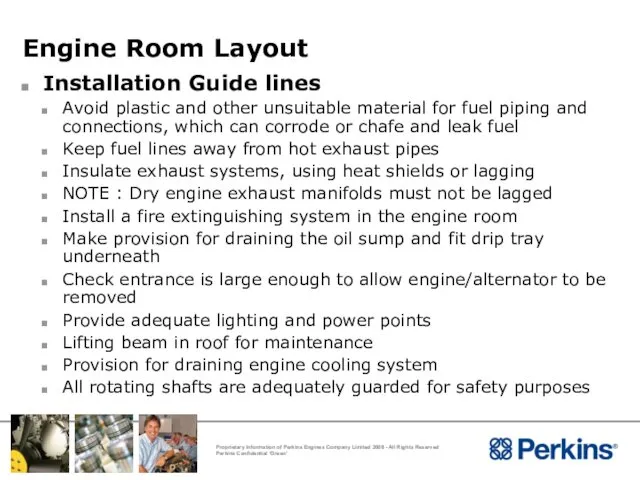
Maintenance, inspection and replacement of parts
Engine Room Layout
Access for Routine Servicing
Maintenance, inspection and replacement of parts
Engine Room Layout
Installation Guide lines
Avoid plastic and other unsuitable material for
Engine Room Layout
Installation Guide lines
Avoid plastic and other unsuitable material for
Engine Room Layout
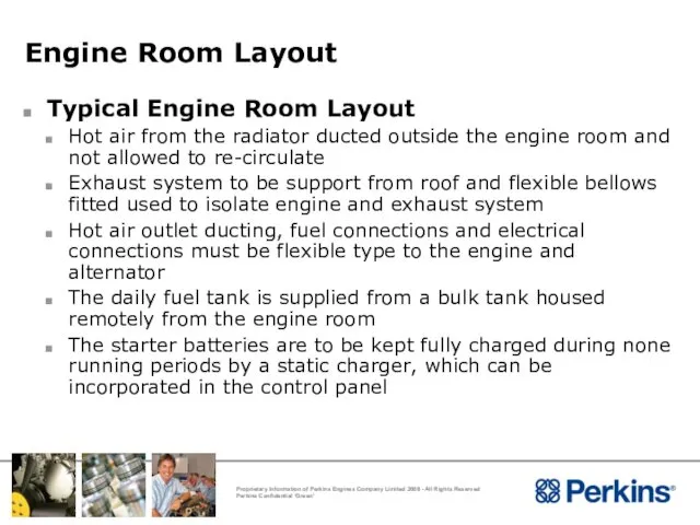
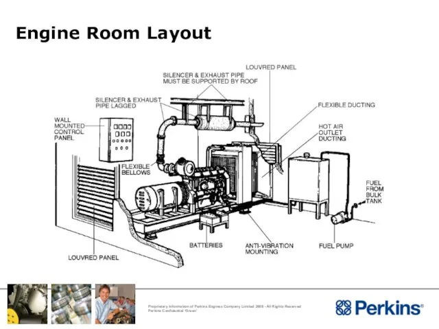
Typical Engine Room Layout
Hot air from the radiator ducted
Engine Room Layout
Typical Engine Room Layout
Hot air from the radiator ducted
Engine Room Layout
Engine Room Layout

Installation Considerations
Ventilation
Installation Considerations
Ventilation
Ventilation
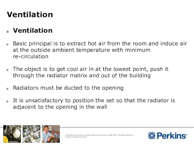
Ventilation
Basic principal is to extract hot air from the room and
Ventilation
Ventilation
Basic principal is to extract hot air from the room and
Ventilation
Ventilation
Ventilation
Ventilation
Ventilation
Ventilation
Ventilation
Outlet/Inlet Sizes
The outlet opening should have a free flow area approximately
Ventilation
Outlet/Inlet Sizes
The outlet opening should have a free flow area approximately
Ventilation
Ventilation
Ventilation
Extract from Institute of Heating & Ventilation Engineers Guide & Wood
Ventilation
Extract from Institute of Heating & Ventilation Engineers Guide & Wood
Ventilation
Extract from Institute of Heating & Ventilation Engineers Guide 1965
Ventilation
Extract from Institute of Heating & Ventilation Engineers Guide 1965
Ventilation
Duct Resistance
Radiator duct allowance must not be exceeded.
Exceeding the duct
Ventilation
Duct Resistance
Radiator duct allowance must not be exceeded.
Exceeding the duct
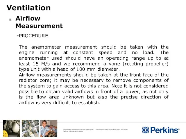
PROCEDURE
The anemometer measurement should be taken with the engine running at
PROCEDURE
The anemometer measurement should be taken with the engine running at
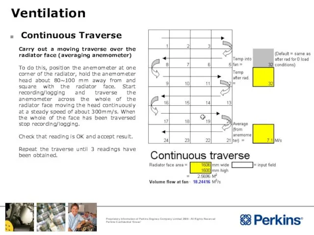
Ventilation
Continuous Traverse
Carry out a moving traverse over the radiator face (averaging
Ventilation
Continuous Traverse
Carry out a moving traverse over the radiator face (averaging
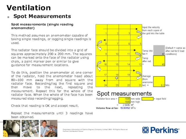
Ventilation
Spot Measurements
Spot measurements (single reading anemometer)
This method assumes an anemometer capable
Ventilation
Spot Measurements
Spot measurements (single reading anemometer)
This method assumes an anemometer capable
Calculation of results
The measured values from either method can then
Calculation of results
The measured values from either method can then
Ventilation
Ducting Against Prevailing Wind
Radiator fan is a “pusher” type
If the prevailing
Ventilation
Ducting Against Prevailing Wind
Radiator fan is a “pusher” type
If the prevailing
Ventilation
Ventilation
Ventilation
Ventilation – Tropical Conditions
To cater for tropical conditions common practice is
Ventilation
Ventilation – Tropical Conditions
To cater for tropical conditions common practice is
Ventilation
Ventilation
Ventilation
Ventilation – Tropical Conditions
Where multiple gensets are installed in an open
Ventilation
Ventilation – Tropical Conditions
Where multiple gensets are installed in an open
Ventilation
Ventilation
Ventilation
Forced Ventilation – Remote Radiator
Exhaust in engine room to be sufficiently
Ventilation
Forced Ventilation – Remote Radiator
Exhaust in engine room to be sufficiently
Ventilation
Ventilation
Ventilation
Forced Ventilation Calculation
To determine the temperature rise in the engine room
Ventilation
Forced Ventilation Calculation
To determine the temperature rise in the engine room
Ventilation
Engine and (Typical) Alternator Radiant Heat to the Engine Room (kWt)
Ventilation
Engine and (Typical) Alternator Radiant Heat to the Engine Room (kWt)
Installation Considerations
Exhaust System
Installation Considerations
Exhaust System
Exhaust Systems
Exhaust System Installation
Keep weight off the turbocharger and exhaust outlet
Exhaust Systems
Exhaust System Installation
Keep weight off the turbocharger and exhaust outlet
Exhaust Systems
Do Not :-
Pipe multiple engine exhausts into a common system
Exhaust Systems
Do Not :-
Pipe multiple engine exhausts into a common system
Exhaust Systems
Exhaust Systems
Exhaust Systems
Exhaust Systems
Exhaust Systems
Exhaust System Terminating in Chimney
Engine twin exhaust outlets may be
Exhaust Systems
Exhaust System Terminating in Chimney
Engine twin exhaust outlets may be
Exhaust Systems
Exhaust Systems Terminating in Chimney - Multiple
Individual exhaust pipes to
Exhaust Systems
Exhaust Systems Terminating in Chimney - Multiple
Individual exhaust pipes to

Exhaust Systems
Piping :-
To prevent build-up of resonant pipe vibrations, long piping
Exhaust Systems
Piping :-
To prevent build-up of resonant pipe vibrations, long piping
Exhaust Systems
Exhaust System Installation
The exhaust system should avoid touching or passing
Exhaust Systems
Exhaust System Installation
The exhaust system should avoid touching or passing
Exhaust Systems
Exhaust System Lagging
To reduce radiated heat from the exhaust pipework
Exhaust Systems
Exhaust System Lagging
To reduce radiated heat from the exhaust pipework
Exhaust Systems
Back Pressure
The exhaust system will produce a certain resistance to
Exhaust Systems
Back Pressure
The exhaust system will produce a certain resistance to
Exhaust Systems
Back Pressure Calculation
Back pressure of a proposed exhaust system can
Exhaust Systems
Back Pressure Calculation
Back pressure of a proposed exhaust system can
Exhaust Systems
Effects of Excessive Exhaust Back Pressure
Too high a back pressure
Exhaust Systems
Effects of Excessive Exhaust Back Pressure
Too high a back pressure
Exhaust Systems
Exhaust Outlet Flange Size
4016 Supplied with :
Twin 250mm BS 10
Exhaust Systems
Exhaust Outlet Flange Size
4016 Supplied with :
Twin 250mm BS 10
Installation Considerations
The Cooling System
Installation Considerations
The Cooling System
Cooling System
Cooling System Requirements
Pressure cap setting 70kPa is maintained in the
Cooling System
Cooling System Requirements
Pressure cap setting 70kPa is maintained in the
Cooling System
Radiator
Note : Product Bulletin 72/13 June 2013
584/365FC cooling group changed
Cooling System
Radiator
Note : Product Bulletin 72/13 June 2013
584/365FC cooling group changed
Cooling System
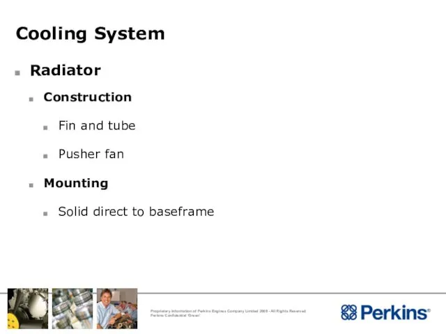
Radiator
Construction
Fin and tube
Pusher fan
Mounting
Solid direct to baseframe
Cooling System
Radiator
Construction
Fin and tube
Pusher fan
Mounting
Solid direct to baseframe
Cooling System
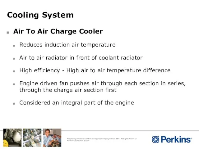
Air To Air Charge Cooler
Reduces induction air temperature
Air to air
Cooling System
Air To Air Charge Cooler
Reduces induction air temperature
Air to air
Cooling System
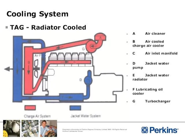
TAG - Radiator Cooled
A Air cleaner
B Air cooled
Cooling System
TAG - Radiator Cooled
A Air cleaner
B Air cooled
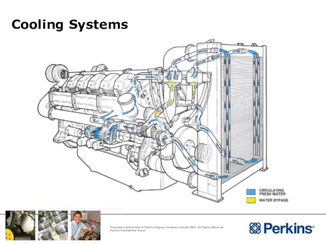
Cooling Systems
Cooling Systems
Cooling System
Air to Air Charge Cooler – Remote
Opening in wall
Cooling System
Air to Air Charge Cooler – Remote
Opening in wall
Cooling Systems
Cooling Systems
Cooling System
Water Pipe and Pressurized Make-up/Vent System – Remote
Coolant pipes to
Cooling System
Water Pipe and Pressurized Make-up/Vent System – Remote
Coolant pipes to
Cooling System
Cooling System
Cooling System
TWG – Radiator Cooled
A Air cleaner
B Water cooled charge air
Cooling System
TWG – Radiator Cooled
A Air cleaner
B Water cooled charge air
Cooling System
TWG – Heat Exchanger Cooled
A Air cleaner
B Water
Cooling System
TWG – Heat Exchanger Cooled
A Air cleaner
B Water
Cooling Systems
Cooling Systems
Cooling System
Protection
Antifreeze
50% mixture
Inhibited ethylene glycol or inhibited propylene glycol
Corrosion Inhibitor –
Cooling System
Protection
Antifreeze
50% mixture
Inhibited ethylene glycol or inhibited propylene glycol
Corrosion Inhibitor –
Cooling System
Ambient Clearance
Stable Top Tank Temperature - Ambient = Rise Over
Cooling System
Ambient Clearance
Stable Top Tank Temperature - Ambient = Rise Over
Cooling System
Blocked Open Thermostats
Always block thermostat open to 11.5mm
Use an
Cooling System
Blocked Open Thermostats
Always block thermostat open to 11.5mm
Use an
Cooling System
Coolant Test Results
Cooling System
Coolant Test Results
Cooling System
Coolant Test Results
Cooling System
Coolant Test Results
Cooling System
Coolant Test Results
Cooling System
Coolant Test Results
Cooling System
Lub. Oil Test Results
Cooling System
Lub. Oil Test Results
Cooling System
Testing / Measurements
Cooling System
Testing / Measurements
Cooling System
Analysis Of Results
Low coolant clearance
Excessive duct restriction
Re-circulation
Cooling System
Analysis Of Results
Low coolant clearance
Excessive duct restriction
Re-circulation
Cooling System
De-Aeration
Possible Causes
Poor filling
Poor venting
Blockages
Cooling System
De-Aeration
Possible Causes
Poor filling
Poor venting
Blockages
Cooling System
De-Aeration
Effects of air in water
Local boiling
Excessive coolant loss
Deterioration of water
Cooling System
De-Aeration
Effects of air in water
Local boiling
Excessive coolant loss
Deterioration of water
Applications Considerations
Cold Start
Applications Considerations
Cold Start
Cold Start
Immersion Heaters
In ambient conditions 10oC and below, it is recommended
Cold Start
Immersion Heaters
In ambient conditions 10oC and below, it is recommended
Installation Considerations
Fuel System
Installation Considerations
Fuel System
Fuel System
The purpose of the fuel system is to ensure:
An ample
Fuel System
The purpose of the fuel system is to ensure:
An ample
Fuel System
Fuel Filtration
Disposable spin-on canister type, with a self venting valve.
Fuel System
Fuel Filtration
Disposable spin-on canister type, with a self venting valve.
Fuel System
Fuel System
Fuel System
Fuel Temperature
Effect engine performance and emissions if fuel inlet temperature
Fuel System
Fuel Temperature
Effect engine performance and emissions if fuel inlet temperature
Fuel System
Fuel Cooler
If a fuel cooler is required it should be
Fuel System
Fuel Cooler
If a fuel cooler is required it should be
Fuel System
Fuel System
Fuel System
Fuel Auxiliary or ‘Day Tanks’
Total suction head must not
Fuel System
Fuel Auxiliary or ‘Day Tanks’
Total suction head must not
Fuel System
Fuel System
Fuel System
Fuel System
Fuel System
Fuel Auxiliary or ‘Day Tanks’
Weirs must be incorporated in the
Fuel System
Fuel Auxiliary or ‘Day Tanks’
Weirs must be incorporated in the
Fuel System
Fuel System
Fuel System
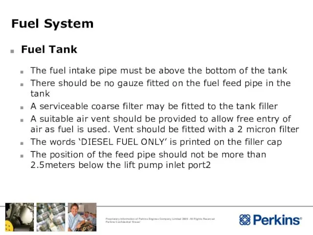
Fuel Tank
The fuel intake pipe must be above the bottom
Fuel System
Fuel Tank
The fuel intake pipe must be above the bottom
Fuel System
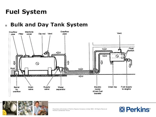
Bulk and Day Tank System
Fuel System
Bulk and Day Tank System
Fuel System
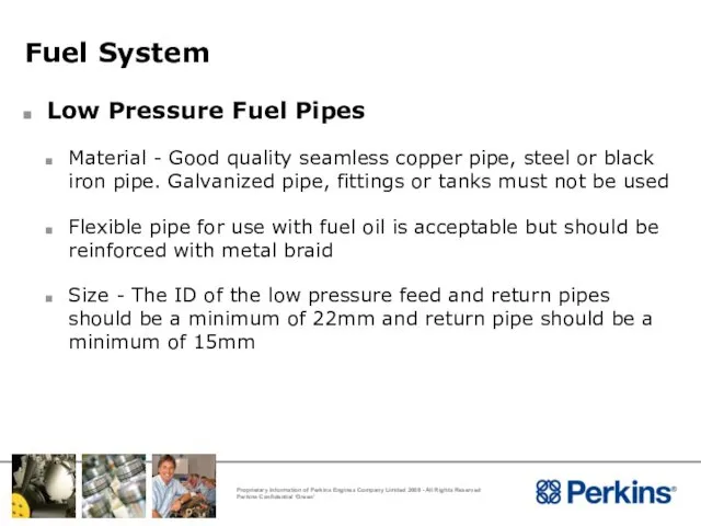
Low Pressure Fuel Pipes
Material - Good quality seamless copper pipe,
Fuel System
Low Pressure Fuel Pipes
Material - Good quality seamless copper pipe,
Fuel System
Water Trap and Sedimenter
A water trap and sedimenter should be
Fuel System
Water Trap and Sedimenter
A water trap and sedimenter should be
Fuel System
Engine Piping
The low pressure fuel system between fuel filter and
Fuel System
Engine Piping
The low pressure fuel system between fuel filter and
Fuel System
Fuel Auxiliary or ‘Day Tanks’
For day tanks installed below the
Fuel System
Fuel Auxiliary or ‘Day Tanks’
For day tanks installed below the
Fuel System
Fuel System
Fuel System
Suitable Fuels for 4016TAG’
Fuel System
Suitable Fuels for 4016TAG’
Installation Considerations
Lubricating Oil System
Installation Considerations
Lubricating Oil System
Lubricating Oil System
Oil Filtration
Disposable canister fitted with by-pass, full flow
Lubricating Oil System
Oil Filtration
Disposable canister fitted with by-pass, full flow
Lubricating Oil System
Lubricating Oil System
Lubricating Oil System
Sump Heaters
There is a possibility of local degrading occurring
Lubricating Oil System
Sump Heaters
There is a possibility of local degrading occurring

Installation Considerations
Crankcase Ventilation
Installation Considerations
Crankcase Ventilation
Crankcase Ventilation
Breather
Check breather exit position, the point of exit of the
Crankcase Ventilation
Breather
Check breather exit position, the point of exit of the
Crankcase Ventilation
Breather
On Vee Form engines with two breathers these can be
Crankcase Ventilation
Breather
On Vee Form engines with two breathers these can be
Crankcase Ventilation
Crankcase Ventilation

Installation Considerations
Electrical Systems
Installation Considerations
Electrical Systems
Electrical Systems
Starter Motors
Engines can be supplied with a suitable 24
Electrical Systems
Starter Motors
Engines can be supplied with a suitable 24
Electrical System
Alternator
All engines are supplied with a battery charging alternator
Alternator
Electrical System
Alternator
All engines are supplied with a battery charging alternator
Alternator
Electrical System
Batteries
There are three main types of battery in circulation these
Electrical System
Batteries
There are three main types of battery in circulation these
Electrical System
Good Wiring Practice
Ensure suitable cables have been used
Where possible cables
Electrical System
Good Wiring Practice
Ensure suitable cables have been used
Where possible cables
Electrical System
Electrical System

Electrical Systems
Protection Devices
4016 are fitted with the following shut-down protection as
Electrical Systems
Protection Devices
4016 are fitted with the following shut-down protection as

Electrical Systems
High Jacket Water Switch (HJW)
Set to 101 o C
Electrical Systems
High Jacket Water Switch (HJW)
Set to 101 o C
Electrical Systems
Low Oil Pressure Switch (LOP)
Set to 193 kPa (Falling)
A
Electrical Systems
Low Oil Pressure Switch (LOP)
Set to 193 kPa (Falling)
A
Electrical Systems
HWT and LOP Deutsch Switch Connections
The switches are fitted with
Electrical Systems
HWT and LOP Deutsch Switch Connections
The switches are fitted with
Electrical Systems
Low Coolant Level Switch (LCL)
Fitted as standard to each
Electrical Systems
Low Coolant Level Switch (LCL)
Fitted as standard to each
Electrical Systems
Turbine Inlet Temperature Switch (TIT)
Set to 735 o C
Electrical Systems
Turbine Inlet Temperature Switch (TIT)
Set to 735 o C
Electrical Systems
Overspeed Switch (OS)
Set to in Overspeed Switch : 1725rpm
Electrical Systems
Overspeed Switch (OS)
Set to in Overspeed Switch : 1725rpm
Electrical Systems
Overspeed Air Shut-Off Valves (ASOV)
Air Shut-off Valves activated by
Electrical Systems
Overspeed Air Shut-Off Valves (ASOV)
Air Shut-off Valves activated by
Electrical Systems
Oil Pressure Switch – Battery Charging Alternator Excitation Circuit
The oil
Electrical Systems
Oil Pressure Switch – Battery Charging Alternator Excitation Circuit
The oil
Applications Considerations
Air Induction System
Applications Considerations
Air Induction System
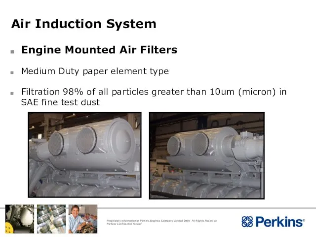
Air Induction System
Engine Mounted Air Filters
Medium Duty paper element type
Filtration
Air Induction System
Engine Mounted Air Filters
Medium Duty paper element type
Filtration
Air Induction System
Air Restriction Indicator
Fitted as standard to each
Air Induction System
Air Restriction Indicator
Fitted as standard to each
Air Induction System
Oil Bath Air Filters
Perkins do not recommend the use
Air Induction System
Oil Bath Air Filters
Perkins do not recommend the use
Air Induction System
Oil Bath Air Filters
Another potentially disastrous problem is that
Air Induction System
Oil Bath Air Filters
Another potentially disastrous problem is that
Installation Considerations
Noise Control
Installation Considerations
Noise Control
Noise Control
Factors Influencing Noise
Radiator fan
Induction system
Exhaust system
Vibration
Noise Control
Factors Influencing Noise
Radiator fan
Induction system
Exhaust system
Vibration
Noise Control
Insulation and Absorption
There are many different ways of reducing noise
Noise Control
Insulation and Absorption
There are many different ways of reducing noise
Noise Control
Genset Position
Noise Control
Genset Position
Noise Control
‘Free Field’
Noise escaping from the engine room into a ‘Free
Noise Control
‘Free Field’
Noise escaping from the engine room into a ‘Free
Noise Control
‘Semi-Reverberant Field’
If the area around the engine room include other
Noise Control
‘Semi-Reverberant Field’
If the area around the engine room include other
Installation Considerations
Governing
Installation Considerations
Governing
Governing
4016 Engines are fitted with Heinzmann E16 series Pandaros Digital
Governing
4016 Engines are fitted with Heinzmann E16 series Pandaros Digital
Governing
System Overview
Governing
System Overview
Governing
Configuration
The engine will be configured are shown below:
Speed
1500rpm or 1800rpm
Droop /
Governing
Configuration
The engine will be configured are shown below:
Speed
1500rpm or 1800rpm
Droop /
Governing
Changing the configuration of the governor
In order to change the configuration
Governing
Changing the configuration of the governor
In order to change the configuration
Governing
Configuration Screen in Pandaros Packager
Governing
Configuration Screen in Pandaros Packager
Governing
Single generator fixed speed
Select the button for Single generator fixed speed
Governing
Single generator fixed speed
Select the button for Single generator fixed speed
Governing
Parallel Generator to Heinzmann LSU/Sync
When the Generator Mode - Parallel
Governing
Parallel Generator to Heinzmann LSU/Sync
When the Generator Mode - Parallel
Governing
Parallel Generator Screen
Governing
Parallel Generator Screen
Governing
Parallel generator other LSU/Sync
There are many possible variations of load sharing
Governing
Parallel generator other LSU/Sync
There are many possible variations of load sharing
Governing
Load Control Configuration Screen
Governing
Load Control Configuration Screen
Governing
Parallel generator other LSU/Sync
ADC 1_Type - The parameter enables the selection
Governing
Parallel generator other LSU/Sync
ADC 1_Type - The parameter enables the selection
Governing
Parallel generator other LSU/Sync
AnalogIn1_ErrorLow - AnalogIn1_ErrorLow sets the lowest value at
Governing
Parallel generator other LSU/Sync
AnalogIn1_ErrorLow - AnalogIn1_ErrorLow sets the lowest value at
Governing
Synchronizer Configuration Screen
Governing
Synchronizer Configuration Screen
Governing
Parallel generator other LSU/Sync
ADC 2_Type - The parameter enables the correct
Governing
Parallel generator other LSU/Sync
ADC 2_Type - The parameter enables the correct
Governing
Parallel generator other LSU/Sync
AnalogIn2_ErrorLow - sets the lowest value at which
Governing
Parallel generator other LSU/Sync
AnalogIn2_ErrorLow - sets the lowest value at which
Governing
System Wiring
The cables (4) between
the system components are
provided and
Governing
System Wiring
The cables (4) between
the system components are
provided and
Governing
External Connections From Cable
Governing
External Connections From Cable
Governing
External Connections From Cable
• B+ : A positive 24 VDC supply
Governing
External Connections From Cable
• B+ : A positive 24 VDC supply
Governing
External Connections From Cable
• A3 - is common for synchronizer/load sharer
Governing
External Connections From Cable
• A3 - is common for synchronizer/load sharer
Governing
External Connections From Cable
• Alarm - This is a digital output
Governing
External Connections From Cable
• Alarm - This is a digital output
Governing
External Connections and the Connector for the Control Box
Governing
External Connections and the Connector for the Control Box
Governing
External Connections
Governing
External Connections
Governing
Cable Sizes
The cables for the supply for the battery must be
Governing
Cable Sizes
The cables for the supply for the battery must be
Governing
Alternative Connections for Speed Setting Inputs
Single or Parallel Generator Variable
Governing
Alternative Connections for Speed Setting Inputs
Single or Parallel Generator Variable
Governing
Alternative Connections for Speed Setting Inputs
Parallel Generator Heinzmann LSU/Sync
Connect A3,
Governing
Alternative Connections for Speed Setting Inputs
Parallel Generator Heinzmann LSU/Sync
Connect A3,
Governing
Alternative Connections for Speed Setting Inputs
Parallel Generator (Heinzmann Thesius)
Governing
Alternative Connections for Speed Setting Inputs
Parallel Generator (Heinzmann Thesius)
Governing
Governor
Performance to ISO 3046 Part 4
4016 to ISO 8528-12 and G2
Governing
Governor
Performance to ISO 3046 Part 4
4016 to ISO 8528-12 and G2
Governing
Generator Applications
Governing
Generator Applications
Governing
Generator Applications
Governing
Generator Applications
Governing
Generator Applications
Governing
Generator Applications
Installation Considerations
Multiple Gensets Installation
Installation Considerations
Multiple Gensets Installation
Multiple Genset Installation
General – same guidelines as for single unit
Each genset
Multiple Genset Installation
General – same guidelines as for single unit
Each genset
Multiple Genset Installation
Multiple Genset Installation
Noise Control
Multiple Engine Noise Level
In multiple genset installation using the
Noise Control
Multiple Engine Noise Level
In multiple genset installation using the
Noise Control
Multiple Engine Noise Level
Using a single engine at a
Noise Control
Multiple Engine Noise Level
Using a single engine at a
Installation Considerations
Data Available To Support Installations
Installation Considerations
Data Available To Support Installations
Technical Data Sheet
Technical Data Sheet (TDS)
A full set of TDS
Technical Data Sheet
Technical Data Sheet (TDS)
A full set of TDS
General Arrangement Drawings
General Arrangement Drawings (GA drawings)
A full set of GA
General Arrangement Drawings
General Arrangement Drawings (GA drawings)
A full set of GA
Derate
Derate
Derate means reducing the engines maximum power rating at normal temperatures
Derate
Derate
Derate means reducing the engines maximum power rating at normal temperatures
Derate
Typical 4016 Derate Tables
Derate
Typical 4016 Derate Tables
Torsional Vibration Analysis
Torsional Vibration Analysis (TVA)
A list of completed TVA’s are
Torsional Vibration Analysis
Torsional Vibration Analysis (TVA)
A list of completed TVA’s are
Cooling Data Requirements
Cooling Data Requirements
A full set of cooling data
Cooling Data Requirements
Cooling Data Requirements
A full set of cooling data
 Повышение эффективности взаимодействия транспортных средств и погрузочно-разгрузочных машин и механизмов на примере ООО ПЭК
 Простейший ремонт сантехнического оборудования
 Технология ремонта унитаза
 Sidorenko_Alina_Sergiyivna
 Картошечка с грибочками
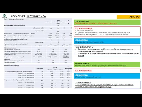 Логистика. Результаты за март 2022 г
 Bumper ads in UAC The Value & Power of 6 Seconds
 Материнская плата
 M5Lesson5
 ЦНППМ: внутренние и внешние ресурсы эффективной деятельности (Чаcть 1)
 Общие понятия о лесозаготовительном производстве. Лекция 1. Основные понятия о лесозаготовительных предприятиях
 Санитарный и противоэпидемиологический контроль
 Бег как средство укрепления здоровья
 Ознакомление с окружающим миром - Деревья и кусты
 День Святого Валентина
 Основы религиозных культур и светской этики
 20160308_prezentatsiya1
 Наша семья
 Направления повышения эффективности деятельности ООО ГБЦ
 Модернизация шлифовального станка
 Профессия Лесопатолог
 Фазовые равновесия с участием фаялитных шлаков в процессах кислородно-факельной плавки
 Декоративно-прикладное искусство моей семьи
 Реконструкция игры властилин замка
 Шаблон презентации исследования
 Безопасность автоматизированных систем в финансовобанковской сфере
 Благотворительная просветительская акция. Рождество приходит к каждому
 20111108_zagadki_o_lete_chast_4