- ERA Glonass Kit Description

Содержание
- 2. ERA Glonass Kit Description ERA Glonass opt & CCM Refurbishing Description Kit Modifications Imposed by Official
- 3. ERA Glonass Kit Description – Components List 1 2 3 4
- 4. TCU EG (Control Unit) Component Description
- 5. Complete Connections Scheme of TCU EG with devices
- 6. GPS / GSM Antenna Module
- 7. Speaker Previous solution, currently assembled on vehicles ex factory
- 8. Button Block
- 9. Global View Of Installation ERA Glonass Kit Description 1 2 3 4
- 10. Cable Routing Components Installation In this area the cable goes closed to the windshield squeezed between
- 11. Specific Cable to connect the system with the Vehicle Reproduction of the vehicle connector for a
- 12. Dashboard Cable Split Signals
- 13. Components Installation 1) TCU EG Remove the glove box, fix the TCU by dual-lock adhesive on
- 14. Device Connection Components Installation TCU EG
- 15. 1) TCU EG Components Installation
- 16. Components installation 2) GPS/GSM Antenna This Antenna has to be glued to the windshield. The 2
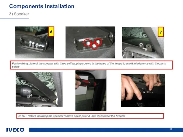
- 17. Components Installation 3) Speaker The speaker has to be fixed to the dashboard A fixing bracket
- 18. 3) Speaker Components Installation
- 19. 3) Speaker Components Installation
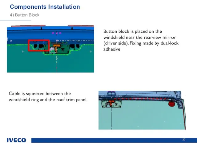
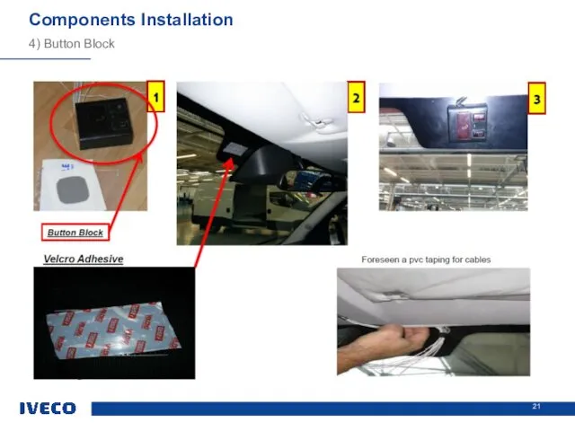
- 20. Components Installation 4) Button Block Button block is placed on the windshield near the rearview mirror
- 21. 4) Button Block Components Installation
- 22. ERA Glonass CCM Refurbishing Description First Phase: disassembly components Sun visors (A and B) Roof trim
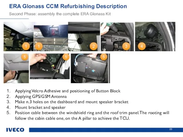
- 23. ERA Glonass CCM Refurbishing Description Second Phase: assembly the complete ERA Glonass Kit Applying Velcro Adhesive
- 24. Opt 72069 (FCS JKF30) to manage the specific dashboard wiring CCM 74742 for the complete kit
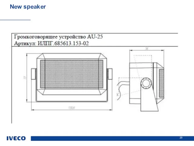
- 25. New speaker
- 27. Скачать презентацию
ERA Glonass Kit Description
ERA Glonass opt & CCM Refurbishing Description
Kit Modifications
ERA Glonass Kit Description
ERA Glonass opt & CCM Refurbishing Description
Kit Modifications
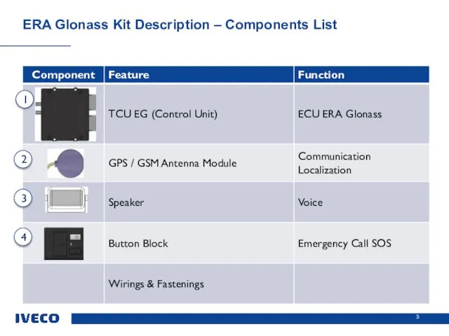
ERA Glonass Kit Description – Components List
1
2
3
4
ERA Glonass Kit Description – Components List
1
2
3
4
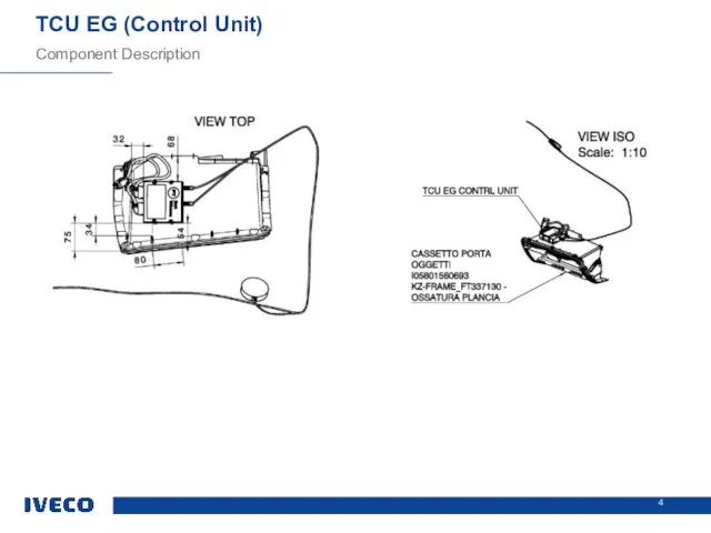
TCU EG (Control Unit)
Component Description
TCU EG (Control Unit)
Component Description
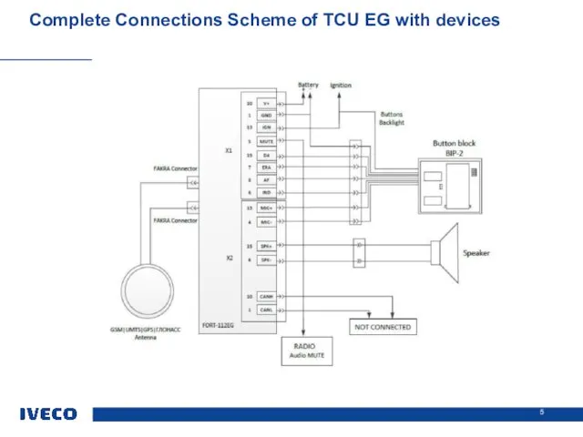
Complete Connections Scheme of TCU EG with devices
Complete Connections Scheme of TCU EG with devices

GPS / GSM Antenna Module
GPS / GSM Antenna Module
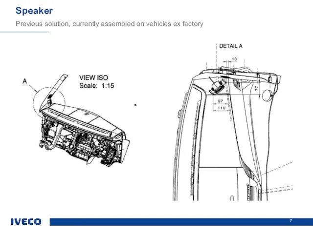
Speaker
Previous solution, currently assembled on vehicles ex factory
Speaker
Previous solution, currently assembled on vehicles ex factory
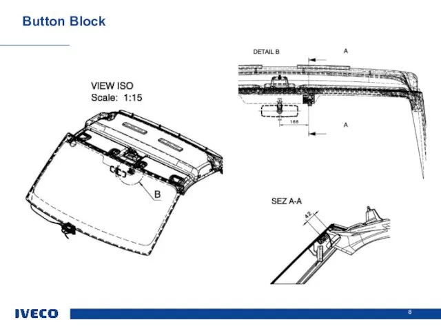
Button Block
Button Block
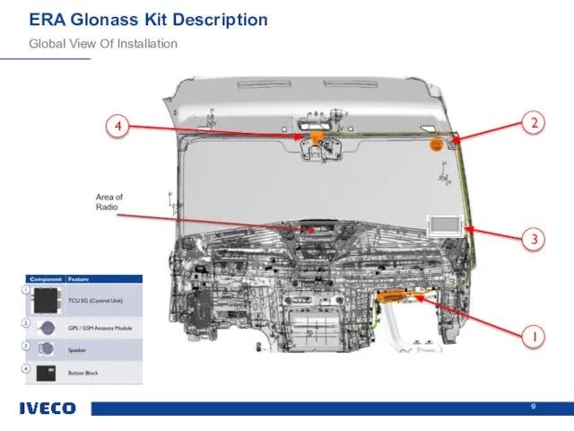
Global View Of Installation
ERA Glonass Kit Description
1
2
3
4
Global View Of Installation
ERA Glonass Kit Description
1
2
3
4
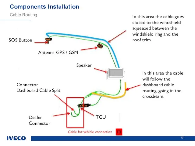
Cable Routing
Components Installation
In this area the cable goes closed to the
Cable Routing
Components Installation
In this area the cable goes closed to the
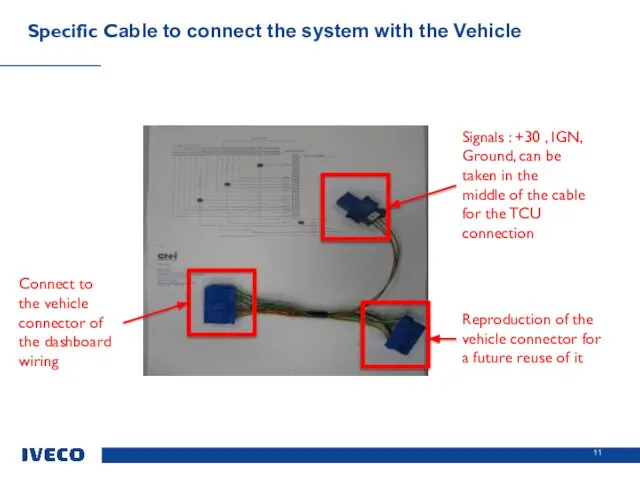
Specific Cable to connect the system with the Vehicle
Reproduction of the
Specific Cable to connect the system with the Vehicle
Reproduction of the
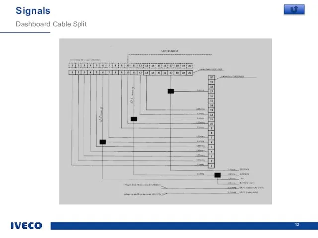
Dashboard Cable Split
Signals
Dashboard Cable Split
Signals
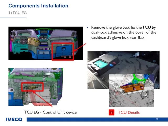
Components Installation
1) TCU EG
Remove the glove box, fix the TCU by
Components Installation
1) TCU EG
Remove the glove box, fix the TCU by
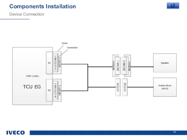
Device Connection
Components Installation
TCU EG
Device Connection
Components Installation
TCU EG
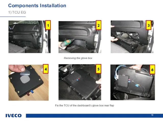
1) TCU EG
Components Installation
1) TCU EG
Components Installation
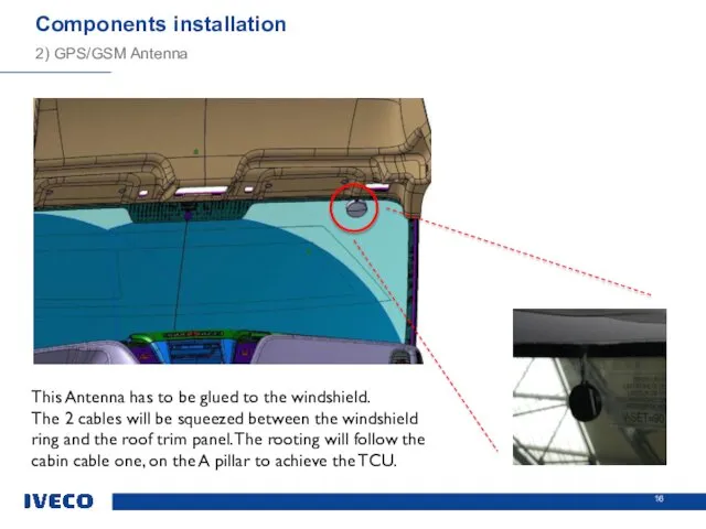
Components installation
2) GPS/GSM Antenna
This Antenna has to be glued to the
Components installation
2) GPS/GSM Antenna
This Antenna has to be glued to the
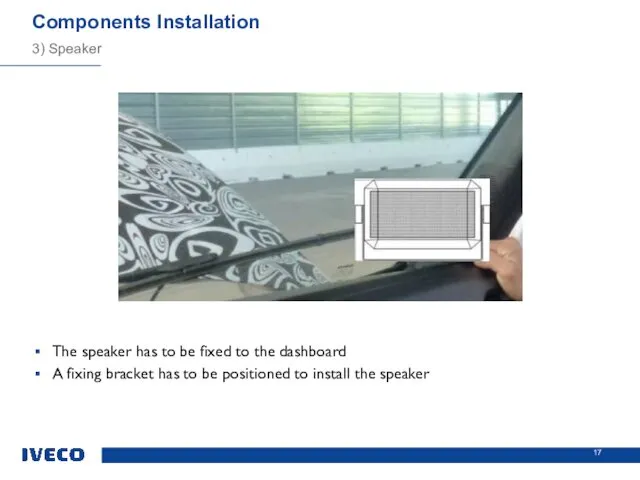
Components Installation
3) Speaker
The speaker has to be fixed to the dashboard
A
Components Installation
3) Speaker
The speaker has to be fixed to the dashboard
A
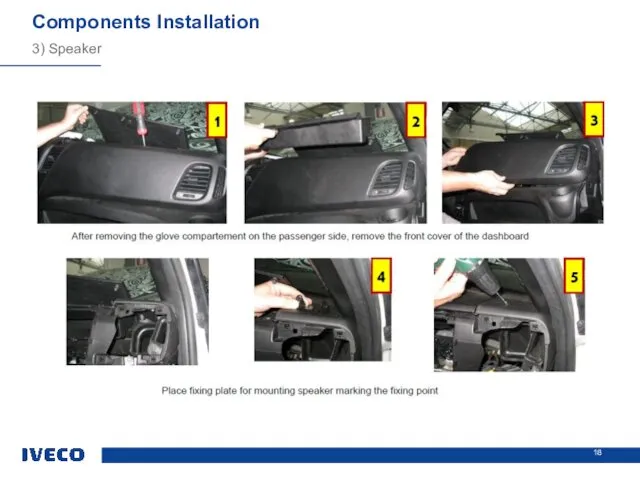
3) Speaker
Components Installation
3) Speaker
Components Installation
3) Speaker
Components Installation
3) Speaker
Components Installation
Components Installation
4) Button Block
Button block is placed on the windshield near
Components Installation
4) Button Block
Button block is placed on the windshield near
4) Button Block
Components Installation
4) Button Block
Components Installation
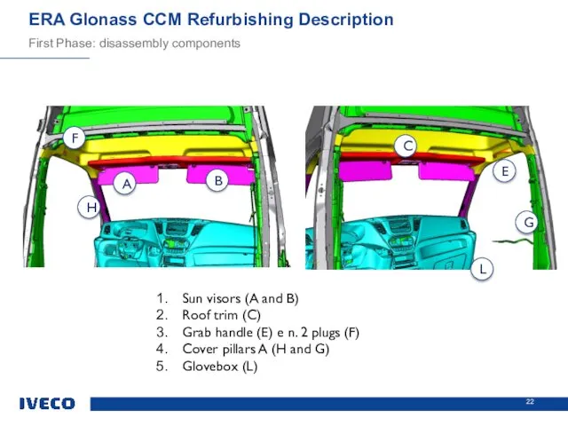
ERA Glonass CCM Refurbishing Description
First Phase: disassembly components
Sun visors (A and
ERA Glonass CCM Refurbishing Description
First Phase: disassembly components
Sun visors (A and
ERA Glonass CCM Refurbishing Description
Second Phase: assembly the complete ERA Glonass
ERA Glonass CCM Refurbishing Description
Second Phase: assembly the complete ERA Glonass
Opt 72069 (FCS JKF30) to manage the specific dashboard wiring
CCM
Opt 72069 (FCS JKF30) to manage the specific dashboard wiring
CCM
New speaker
New speaker
 Задачи использования ЦОР
 Технология изготовления полупроводниковых тонкопленочных резисторов и конденсаторов
 Зонды, используемые в ИОРАН
 Las Vegas
 Парын тап 6-7 яшь
 Тема: Поисковые технические средства
 Исследование водопоглощения текстильных материалов с кардной системой пряжи
 ТОиР
ТОиР Nominasiyalar
 День педагога. Зі святом. дорогі колеги
 Отчет по производственной практике
 Системный подход в моделировании
 Анализ технологии передачи данных на физическом и канальном уровнях для аудиовизуальной информационной системы реального времени
 Электрические печи сопротивления
 Полевые транзисторы. Основные сведения и классификация
 Компания ООО Центр электронного обслуживания
 День матери
 Электроника (фонетика). Квантовые компьютеры. Развитие многофункциональных ИТ инструментов
 школьные годы
 От простого к сложному
 География транспорта. Мировая транспортная система
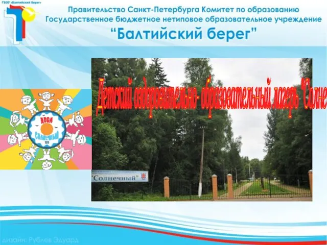 ДООЛ Солнечный
 Реализация проекта на базе СКУД
 Введение. Классификация строительных материалов
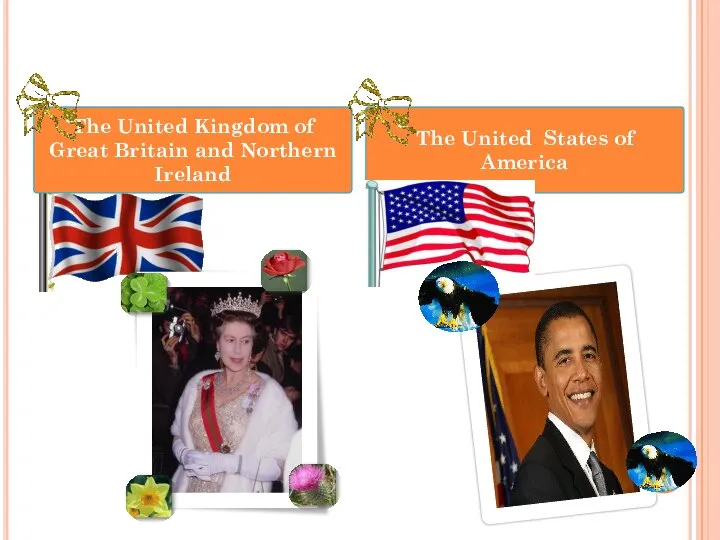 Countryside/ The United Kingdom of Great Britain and Northern Ireland vs The United States of America
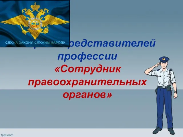 5 ярких представителей профессии Сотрудник правоохранительных органов
 Действительно ли вы лидер,
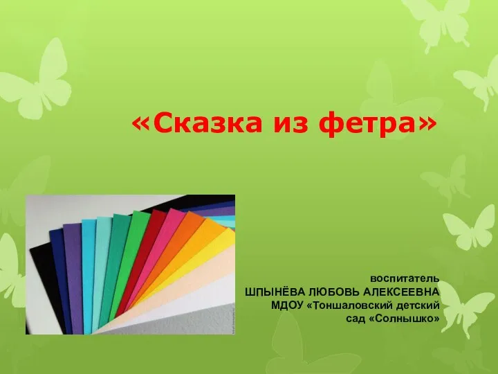 Сказка из фетра