- Process, Power and Marine Division. Piping Task

Содержание
- 2. © 2009. Intergraph Corporation. All Rights Reserved. Agenda Piping Hierarchy Route Pipes Inserting Components Routing a
- 3. © 20049. Intergraph Corporation. All Rights Reserved. Agenda Conti’ Manipulating Views Creating Spools Sequencing Objects Creating
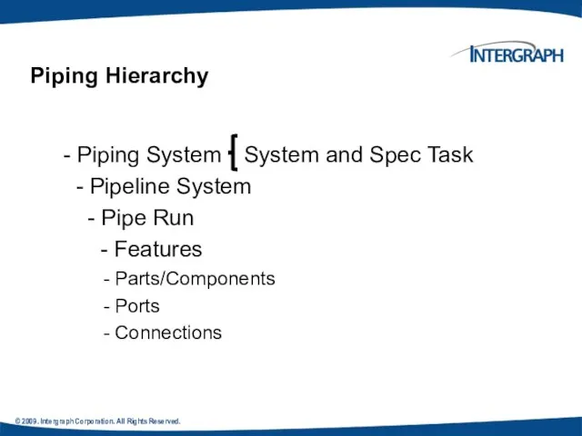
- 4. © 2009. Intergraph Corporation. All Rights Reserved. - Piping System System and Spec Task - Pipeline
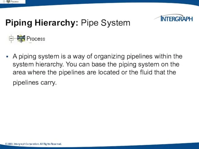
- 5. © 2009. Intergraph Corporation. All Rights Reserved. Piping Hierarchy: Pipe System A piping system is a
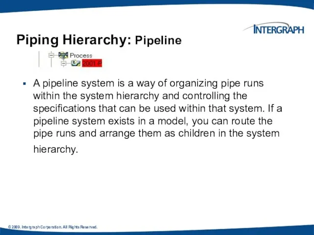
- 6. © 2009. Intergraph Corporation. All Rights Reserved. A pipeline system is a way of organizing pipe
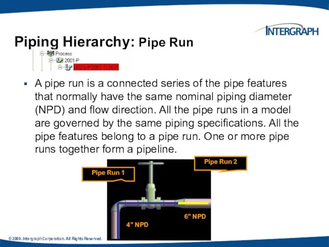
- 7. © 2009. Intergraph Corporation. All Rights Reserved. . A pipe run is a connected series of
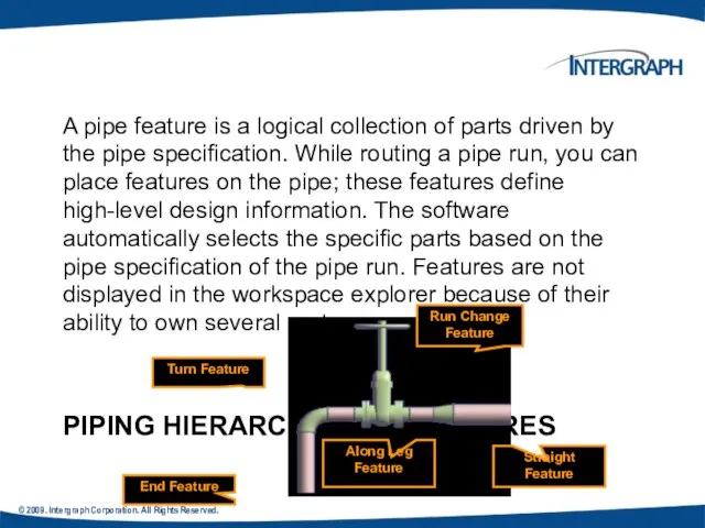
- 8. PIPING HIERARCHY: PIPE FEATURES A pipe feature is a logical collection of parts driven by the
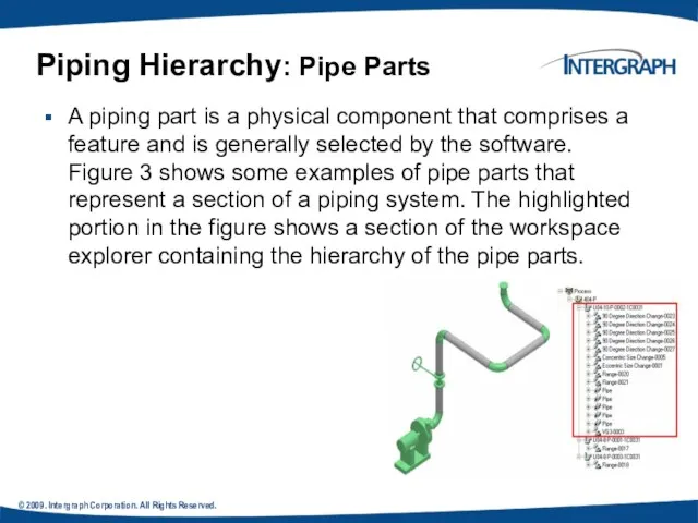
- 9. © 2009. Intergraph Corporation. All Rights Reserved. A piping part is a physical component that comprises
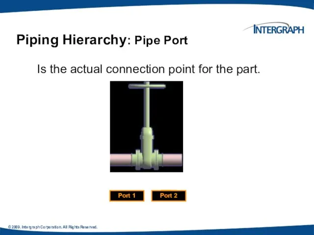
- 10. © 2009. Intergraph Corporation. All Rights Reserved. Is the actual connection point for the part. Piping
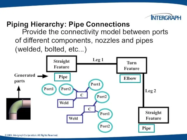
- 11. © 2009. Intergraph Corporation. All Rights Reserved. Provide the connectivity model between ports of different components,
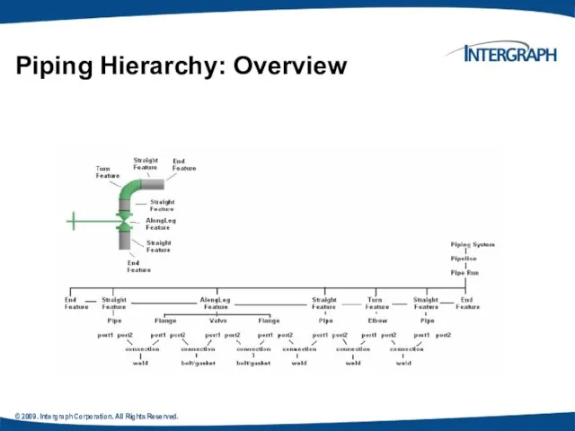
- 12. © 2009. Intergraph Corporation. All Rights Reserved. Piping Hierarchy: Overview
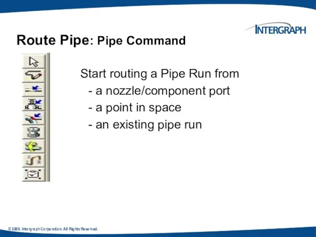
- 13. © 2009. Intergraph Corporation. All Rights Reserved. Start routing a Pipe Run from - a nozzle/component
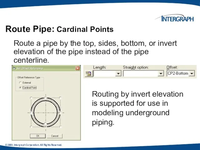
- 14. © 2009. Intergraph Corporation. All Rights Reserved. Route Pipe: Cardinal Points Route a pipe by the
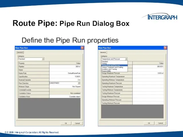
- 15. © © 2009. Intergraph Corporation. All Rights Reserved. Define the Pipe Run properties Route Pipe: Pipe
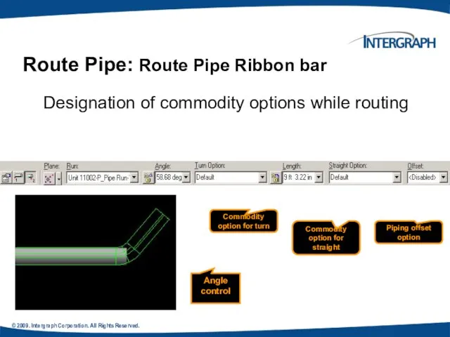
- 16. © 2009. Intergraph Corporation. All Rights Reserved. Route Pipe: Route Pipe Ribbon bar Designation of commodity
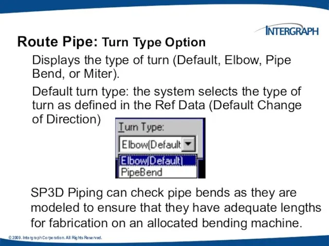
- 17. © 2009. Intergraph Corporation. All Rights Reserved. Route Pipe: Turn Type Option Displays the type of
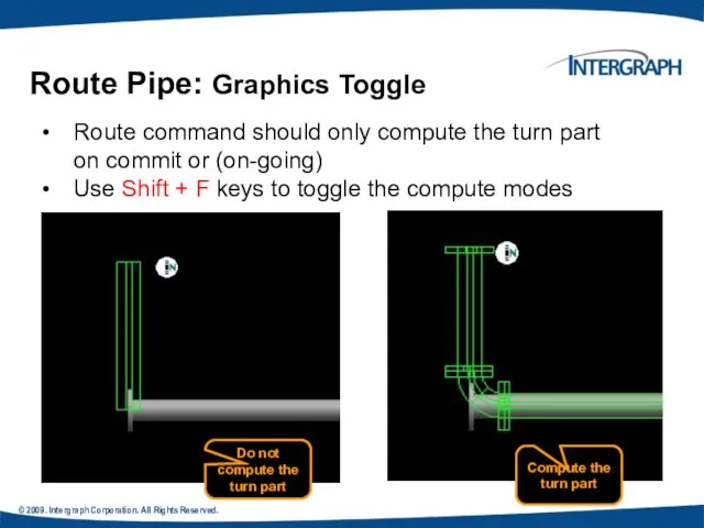
- 18. © 2009. Intergraph Corporation. All Rights Reserved. Route Pipe: Graphics Toggle Route command should only compute
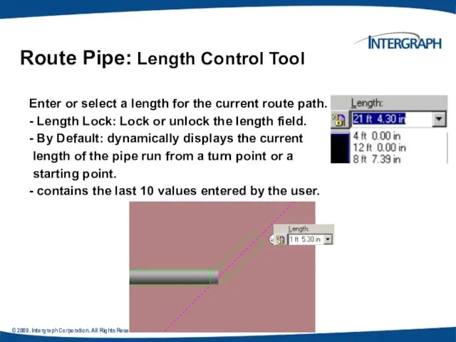
- 19. © 2009. Intergraph Corporation. All Rights Reserved. Route Pipe: Length Control Tool Enter or select a
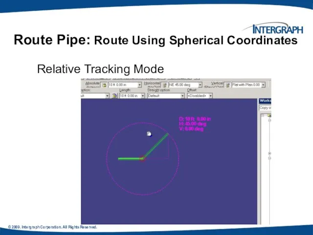
- 20. © 2009. Intergraph Corporation. All Rights Reserved. Relative Tracking Mode Route Pipe: Route Using Spherical Coordinates
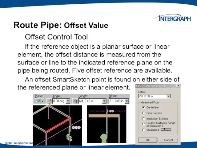
- 21. © 2009. Intergraph Corporation. All Rights Reserved. All Rights Reserved. Offset Control Tool If the reference
- 22. © 2009. Intergraph Corporation. All Rights Reserved. Route Pipe: Offset value How the Solver finds the
- 23. © 2004. Intergraph Corporation. All Rights Reserved. Route Pipe: SmartSketch
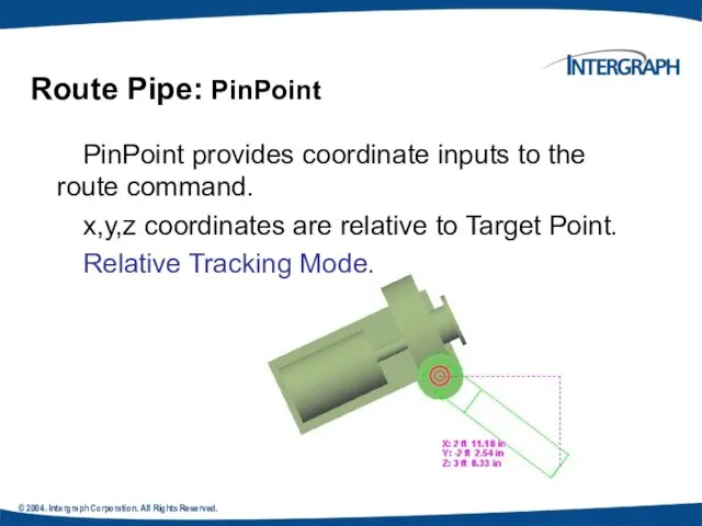
- 24. © 2004. Intergraph Corporation. All Rights Reserved. PinPoint provides coordinate inputs to the route command. x,y,z
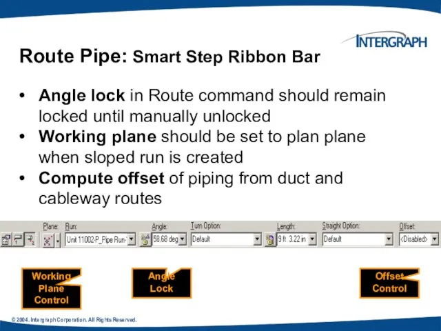
- 25. © 2004. Intergraph Corporation. All Rights Reserved. Angle lock in Route command should remain locked until
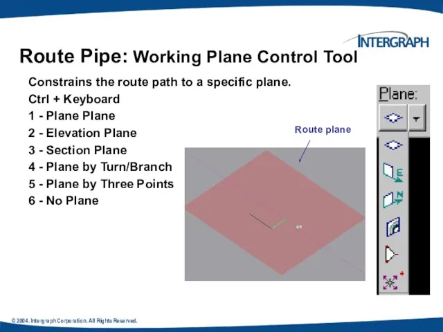
- 26. © 2004. Intergraph Corporation. All Rights Reserved. Route Pipe: Working Plane Control Tool Constrains the route
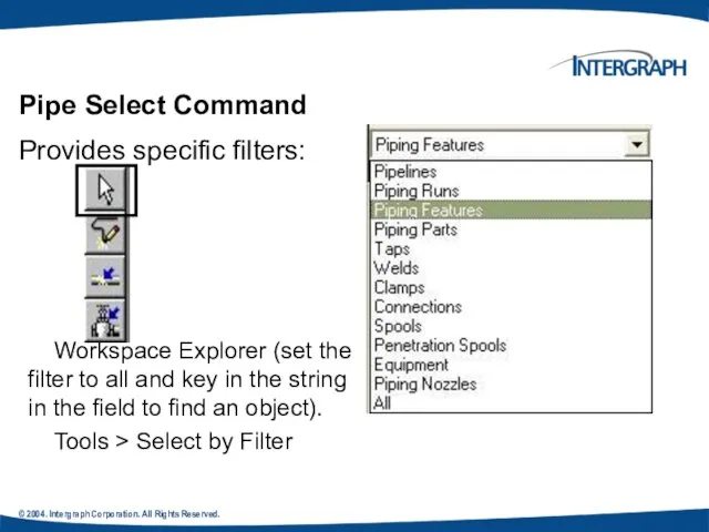
- 27. © 2004. Intergraph Corporation. All Rights Reserved. Pipe Select Command Provides specific filters: Workspace Explorer (set
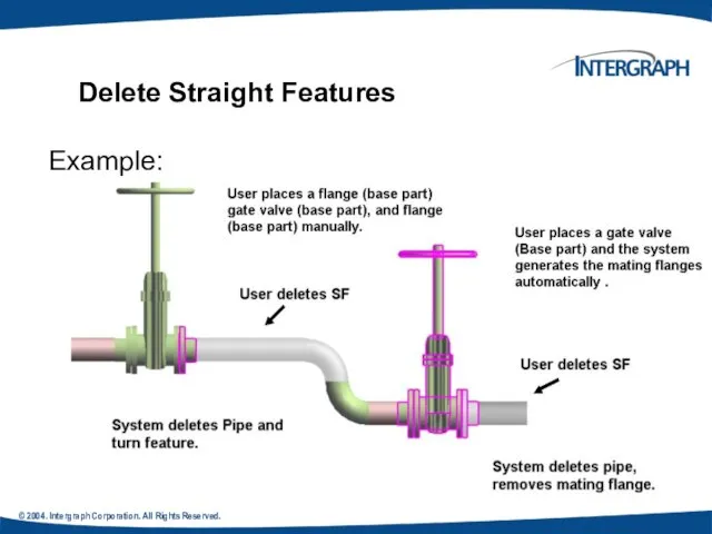
- 28. © 2004. Intergraph Corporation. All Rights Reserved. Deleting a pipeline deletes all pipe runs, features, and
- 29. © 2004. Intergraph Corporation. All Rights Reserved. Deleting the run deletes all features (and thereby all
- 30. © 2004. Intergraph Corporation. All Rights Reserved. Example: Delete Straight Features
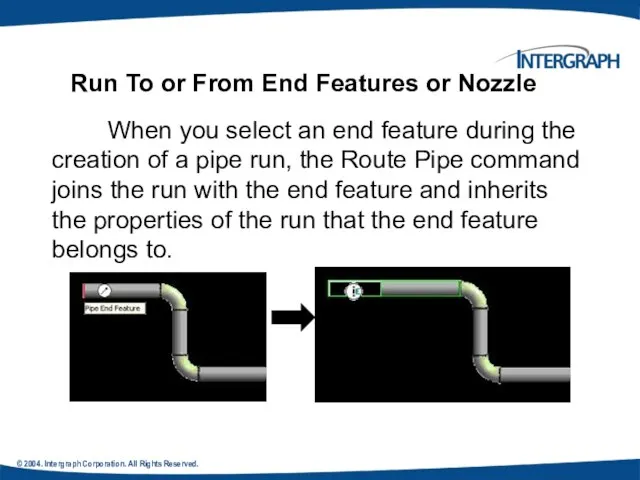
- 31. © 2004. Intergraph Corporation. All Rights Reserved. When you select an end feature during the creation
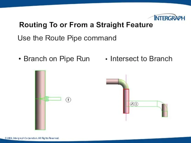
- 32. © 2004. Intergraph Corporation. All Rights Reserved. Routing To or From a Straight Feature Use the
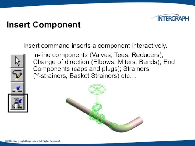
- 33. © 2004. Intergraph Corporation. All Rights Reserved. Insert Component Insert command inserts a component interactively. In-line
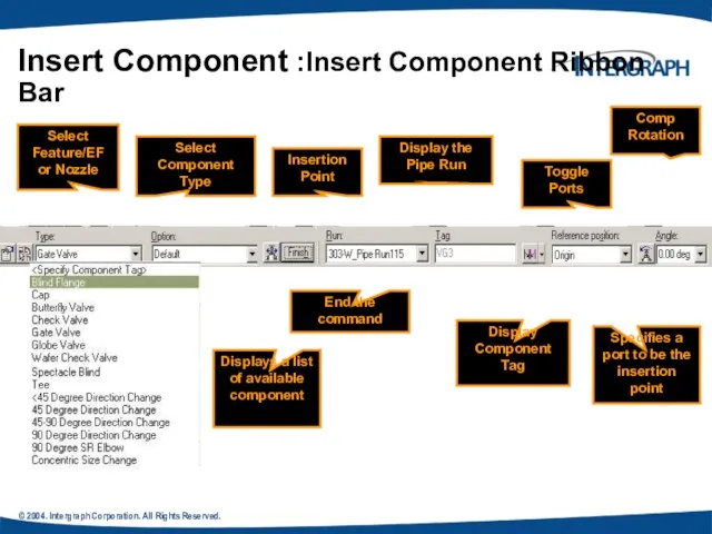
- 34. © 2004. Intergraph Corporation. All Rights Reserved. Insert Component :Insert Component Ribbon Bar Select Feature/EF or
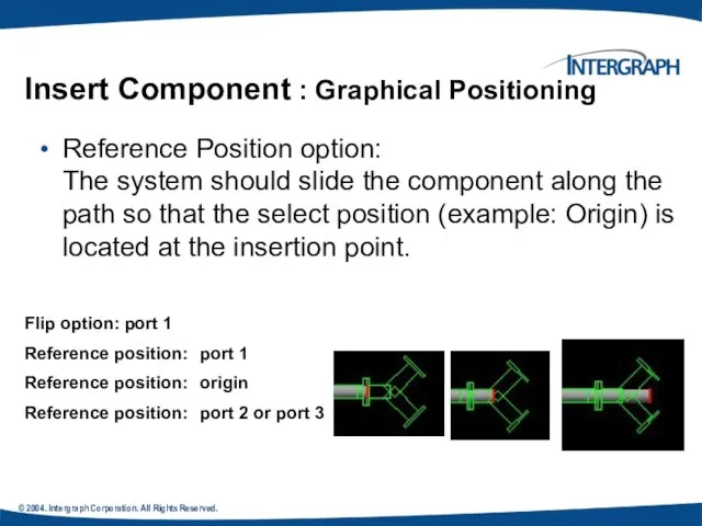
- 35. © 2004. Intergraph Corporation. All Rights Reserved. Insert Component : Graphical Positioning Reference Position option: The
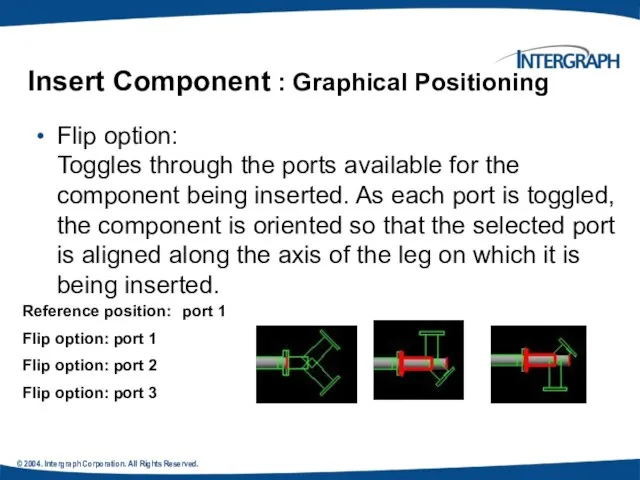
- 36. © 2004. Intergraph Corporation. All Rights Reserved. Insert Component : Graphical Positioning Flip option: Toggles through
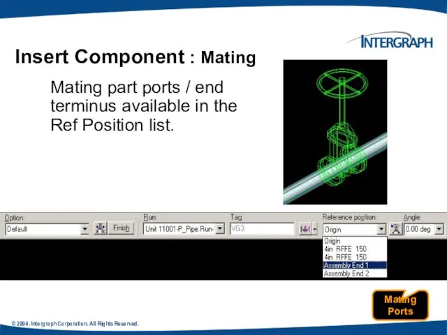
- 37. © 2004. Intergraph Corporation. All Rights Reserved. Insert Component : Mating Mating part ports / end
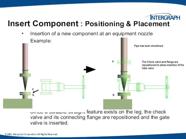
- 38. © 2009. Intergraph Corporation. All Rights Reserved. Insert Component : Positioning & Placement Insertion of a
- 39. © 2009. Intergraph Corporation. All Rights Reserved. Routing Sloped Pipe Underground piping collects drains from funnels
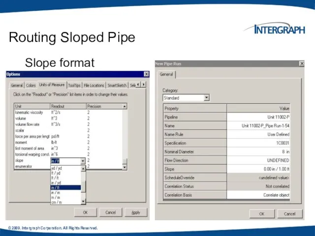
- 40. © 2009. Intergraph Corporation. All Rights Reserved. Slope format Routing Sloped Pipe
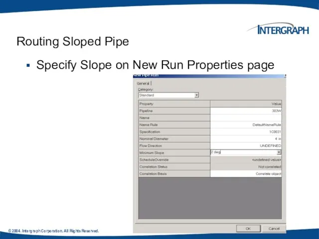
- 41. © 2004. Intergraph Corporation. All Rights Reserved. Routing Sloped Pipe Specify Slope on New Run Properties
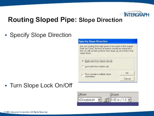
- 42. © 2009. Intergraph Corporation. All Rights Reserved. Routing Sloped Pipe: Slope Direction Specify Slope Direction Turn
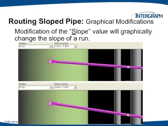
- 43. © 2009. Intergraph Corporation. All Rights Reserved. Reserved. Modification of the “Slope” value will graphically change
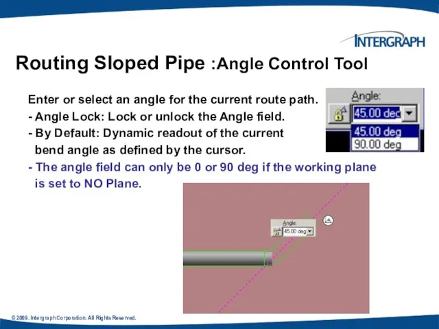
- 44. © 2009. Intergraph Corporation. All Rights Reserved. Routing Sloped Pipe :Angle Control Tool Enter or select
- 45. © 2009. Intergraph Corporation. All Rights Reserved. Piping Practice Labs Route Pipes Inserting Components in a
- 46. © 2009. Intergraph Corporation. All Rights Reserved. Integrated Environment While designing or creating a plant in
- 47. © 2004. Intergraph Corporation. All Rights Reserved. Retrieving Data from a P&ID You can retrieve piping,
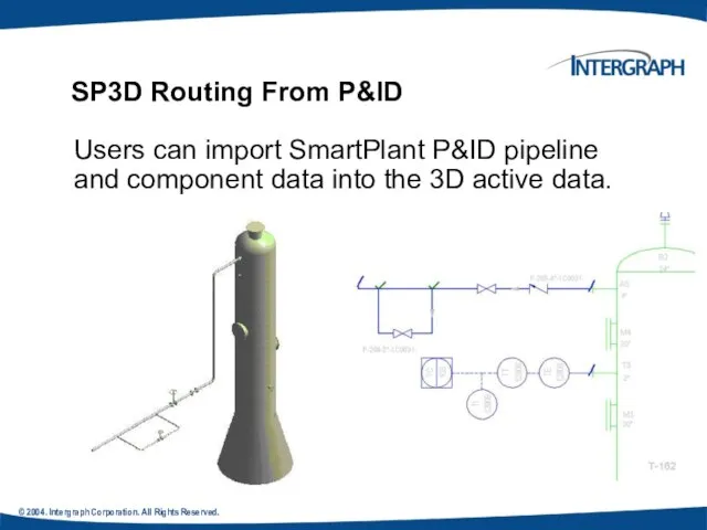
- 48. © 2004. Intergraph Corporation. All Rights Reserved. SP3D Routing From P&ID Users can import SmartPlant P&ID
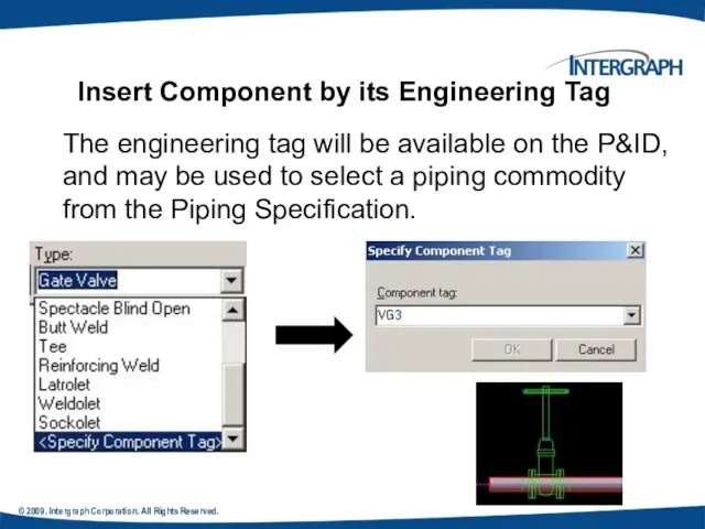
- 49. © 2009. Intergraph Corporation. All Rights Reserved. The engineering tag will be available on the P&ID,
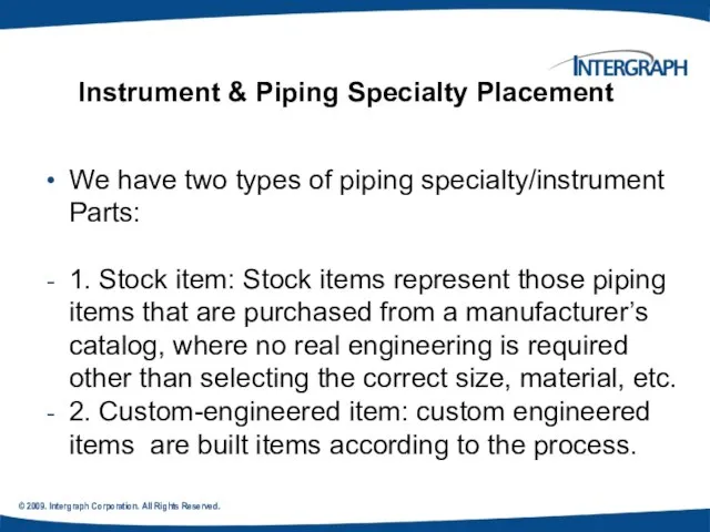
- 50. © 2009. Intergraph Corporation. All Rights Reserved. Instrument & Piping Specialty Placement We have two types
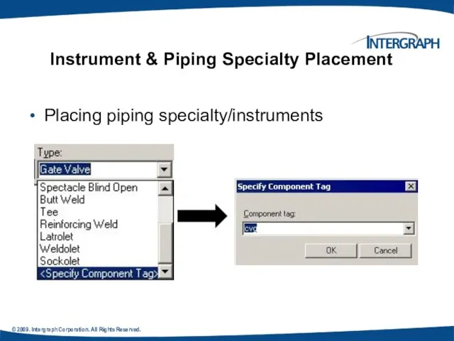
- 51. © 2009. Intergraph Corporation. All Rights Reserved. Instrument & Piping Specialty Placement Placing piping specialty/instruments
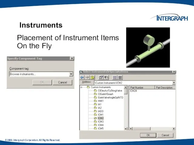
- 52. © 2009. Intergraph Corporation. All Rights Reserved. Instruments Placement of Instrument Items On the Fly
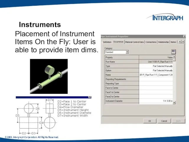
- 53. © 2009. Intergraph Corporation. All Rights Reserved. Placement of Instrument Items On the Fly: User is
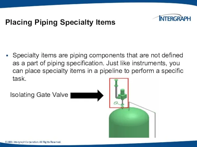
- 54. © 2009. Intergraph Corporation. All Rights Reserved. Placing Piping Specialty Items Specialty items are piping components
- 55. © 2004. Intergraph Corporation. All Rights Reserved. Piping Specialty Items Types Stock specialty items: These items
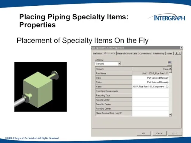
- 56. © 2009. Intergraph Corporation. All Rights Reserved. Placing Piping Specialty Items: Properties Placement of Specialty Items
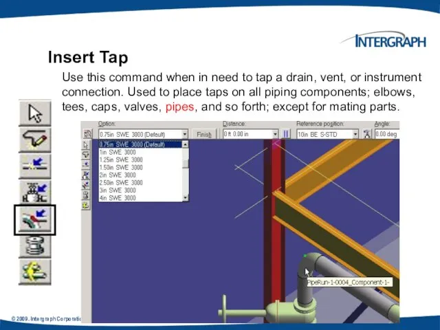
- 57. © 2009. Intergraph Corporation. All Rights Reserved. Insert Tap Use this command when in need to
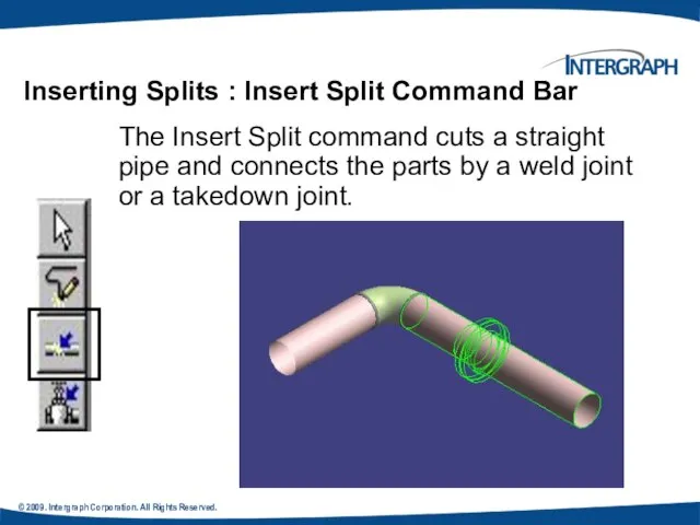
- 58. © 2009. Intergraph Corporation. All Rights Reserved. Inserting Splits : Insert Split Command Bar The Insert
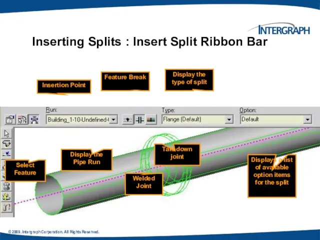
- 59. © 2009. Intergraph Corporation. All Rights Reserved. Inserting Splits : Insert Split Ribbon Bar Welded Joint
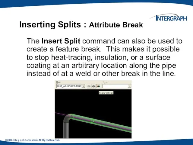
- 60. © 2009. Intergraph Corporation. All Rights Reserved. Inserting Splits : Attribute Break The Insert Split command
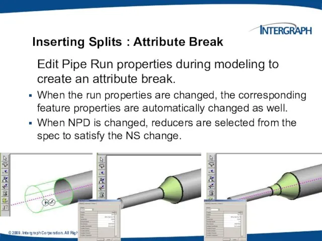
- 61. © 2009. Intergraph Corporation. All Rights Reserved. . Edit Pipe Run properties during modeling to create
- 62. © 2009. Intergraph Corporation. All Rights Reserved. Routing Pipes from P&ID Placing Piping Instruments Placing Piping
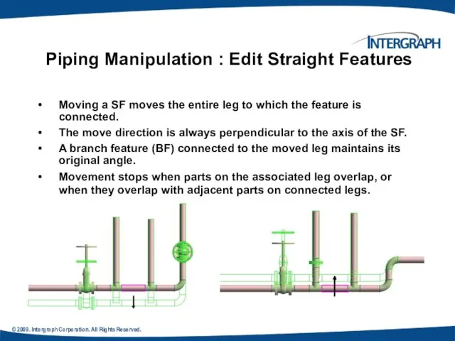
- 63. © 2009. Intergraph Corporation. All Rights Reserved. Piping Manipulation : Edit Straight Features Moving a SF
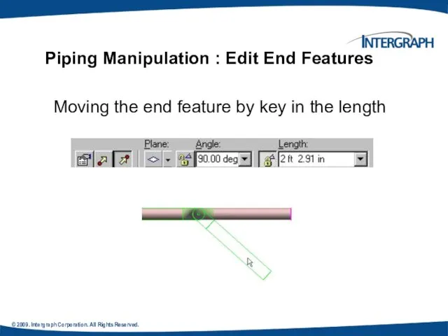
- 64. © 2009. Intergraph Corporation. All Rights Reserved. Piping Manipulation : Edit End Features Moving the end
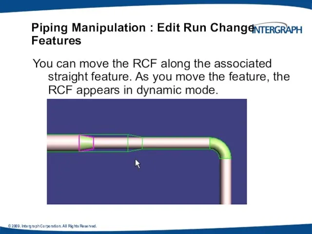
- 65. © 2009. Intergraph Corporation. All Rights Reserved. Piping Manipulation : Edit Run Change Features You can
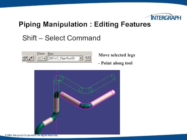
- 66. © 2004. Intergraph Corporation. All Rights Reserved. Piping Manipulation : Editing Features Shift – Select Command
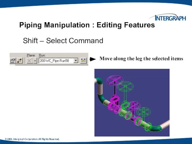
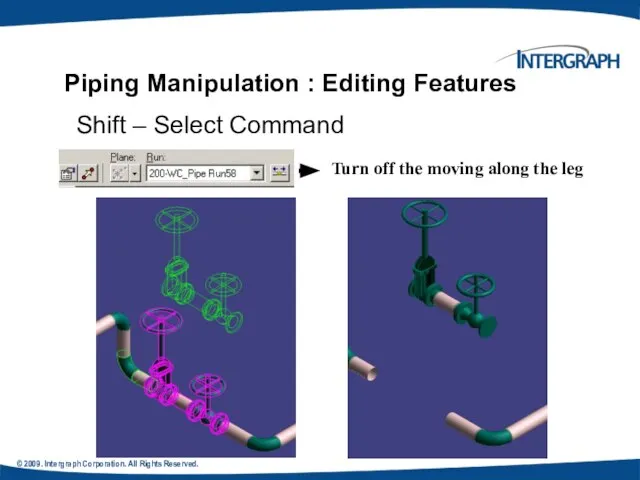
- 67. © 2009. Intergraph Corporation. All Rights Reserved. Piping Manipulation : Editing Features Shift – Select Command
- 68. © 2009. Intergraph Corporation. All Rights Reserved. Piping Manipulation : Editing Features Shift – Select Command
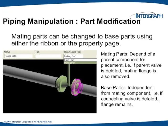
- 69. © 2009. Intergraph Corporation. All Rights Reserved. Mating parts can be changed to base parts using
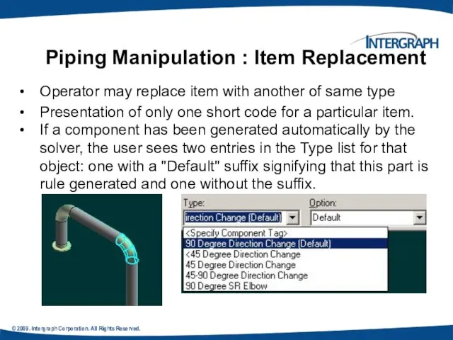
- 70. © 2009. Intergraph Corporation. All Rights Reserved. Operator may replace item with another of same type
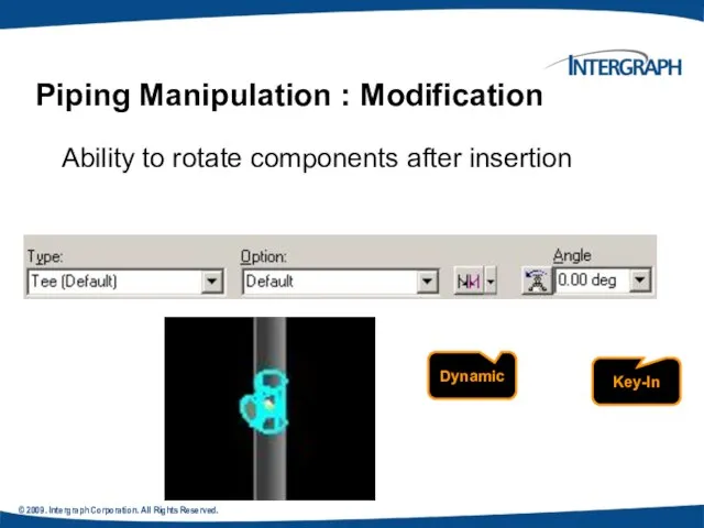
- 71. © 2009. Intergraph Corporation. All Rights Reserved. . New Enhancement in V4 Ability to rotate components
- 72. © 2009. Intergraph Corporation. All Rights Reserved. New Enhancement in V4 Copy/Paste commands are available Mirror
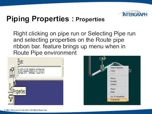
- 73. © 2009. Intergraph Corporation. All Rights Reserved. Right clicking on pipe run or Selecting Pipe run
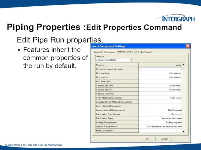
- 74. © 2009. Intergraph Corporation. All Rights Reserved. . Piping Properties :Edit Properties Command Edit Pipe Run
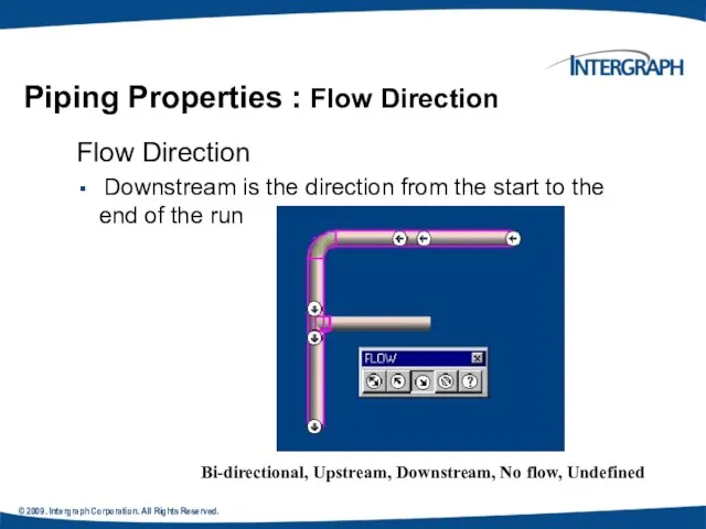
- 75. © 2009. Intergraph Corporation. All Rights Reserved. Piping Properties : Flow Direction Flow Direction Downstream is
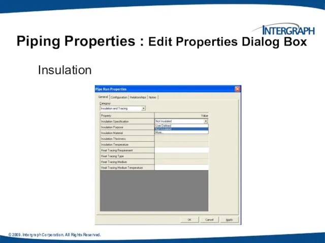
- 76. © 2009. Intergraph Corporation. All Rights Reserved. Piping Properties : Edit Properties Dialog Box Insulation
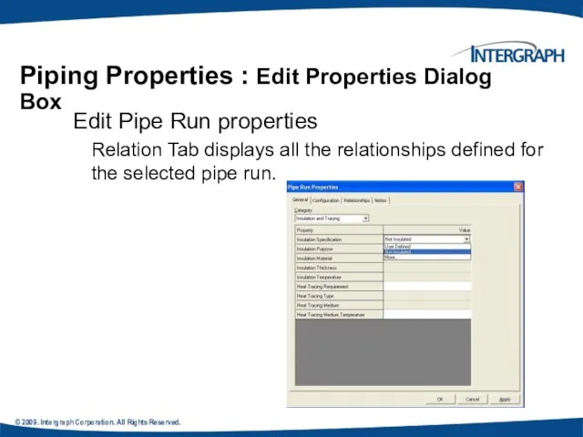
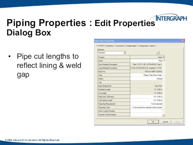
- 77. © 2009. Intergraph Corporation. All Rights Reserved. Piping Properties : Edit Properties Dialog Box Edit Pipe
- 78. © 2009. Intergraph Corporation. All Rights Reserved. Pipe cut lengths to reflect lining & weld gap
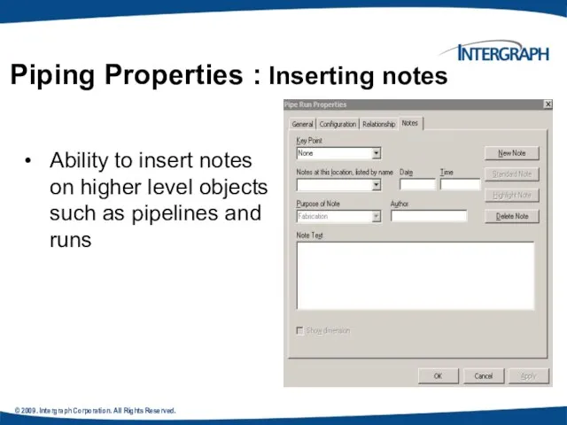
- 79. © 2009. Intergraph Corporation. All Rights Reserved. Ability to insert notes on higher level objects such
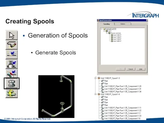
- 80. © 2009. Intergraph Corporation. All Rights Reserved. Creating Spools Generation of Spools Generate Spools
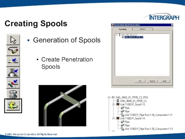
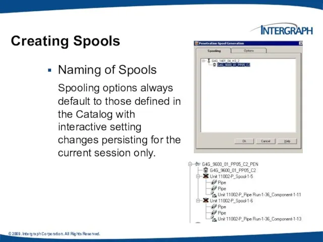
- 81. © 2009. Intergraph Corporation. All Rights Reserved. Generation of Spools Create Penetration Spools Creating Spools
- 82. © 2009. Intergraph Corporation. All Rights Reserved. Naming of Spools Spooling options always default to those
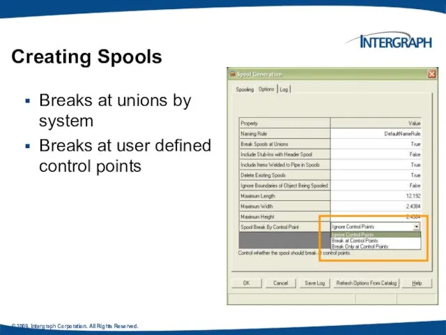
- 83. © 2009. Intergraph Corporation. All Rights Reserved. Breaks at unions by system Breaks at user defined
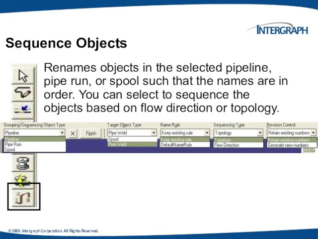
- 84. © 2009. Intergraph Corporation. All Rights Reserved. . Sequence Objects Renames objects in the selected pipeline,
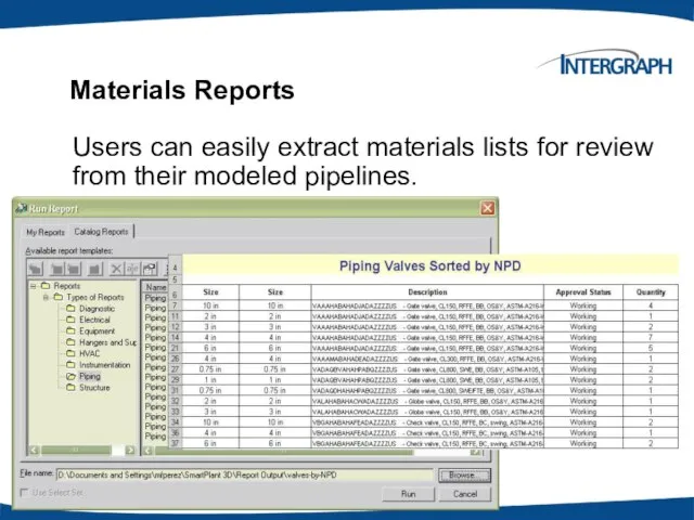
- 85. © 2004. Intergraph Corporation. All Rights Reserved. Materials Reports Users can easily extract materials lists for
- 86. © 2004. Intergraph Corporation. All Rights Reserved. Manipulating Piping Objects Creating Spools Sequencing Objects Creating Isometric
- 88. Скачать презентацию
© 2009. Intergraph Corporation. All Rights Reserved.
Agenda
Piping Hierarchy
Route Pipes
Inserting Components
Routing a
© 2009. Intergraph Corporation. All Rights Reserved.
Agenda
Piping Hierarchy
Route Pipes
Inserting Components
Routing a
© 20049. Intergraph Corporation. All Rights Reserved.
Agenda Conti’
Manipulating Views
Creating Spools
Sequencing Objects
Creating
© 20049. Intergraph Corporation. All Rights Reserved.
Agenda Conti’
Manipulating Views
Creating Spools
Sequencing Objects
Creating
© 2009. Intergraph Corporation. All Rights Reserved.
- Piping System System and
© 2009. Intergraph Corporation. All Rights Reserved.
- Piping System System and
© 2009. Intergraph Corporation. All Rights Reserved.
Piping Hierarchy: Pipe System
A piping
© 2009. Intergraph Corporation. All Rights Reserved.
Piping Hierarchy: Pipe System
A piping
© 2009. Intergraph Corporation. All Rights Reserved.
A pipeline system is a
© 2009. Intergraph Corporation. All Rights Reserved.
A pipeline system is a
© 2009. Intergraph Corporation. All Rights Reserved.
.
A pipe run is a
© 2009. Intergraph Corporation. All Rights Reserved.
.
A pipe run is a
PIPING HIERARCHY: PIPE FEATURES
A pipe feature is a logical collection of
PIPING HIERARCHY: PIPE FEATURES
A pipe feature is a logical collection of
© 2009. Intergraph Corporation. All Rights Reserved.
A piping part is a
© 2009. Intergraph Corporation. All Rights Reserved.
A piping part is a
© 2009. Intergraph Corporation. All Rights Reserved.
Is the actual connection point
© 2009. Intergraph Corporation. All Rights Reserved.
Is the actual connection point
© 2009. Intergraph Corporation. All Rights Reserved.
Provide the connectivity model between
© 2009. Intergraph Corporation. All Rights Reserved.
Provide the connectivity model between
© 2009. Intergraph Corporation. All Rights Reserved.
Piping Hierarchy: Overview
© 2009. Intergraph Corporation. All Rights Reserved.
Piping Hierarchy: Overview
© 2009. Intergraph Corporation. All Rights Reserved.
Start routing a Pipe Run
© 2009. Intergraph Corporation. All Rights Reserved.
Start routing a Pipe Run
© 2009. Intergraph Corporation. All Rights Reserved.
Route Pipe: Cardinal Points
Route a
© 2009. Intergraph Corporation. All Rights Reserved.
Route Pipe: Cardinal Points
Route a
© © 2009. Intergraph Corporation. All Rights Reserved.
Define the Pipe Run
© © 2009. Intergraph Corporation. All Rights Reserved.
Define the Pipe Run
© 2009. Intergraph Corporation. All Rights Reserved.
Route Pipe: Route Pipe Ribbon
© 2009. Intergraph Corporation. All Rights Reserved.
Route Pipe: Route Pipe Ribbon
© 2009. Intergraph Corporation. All Rights Reserved.
Route Pipe: Turn Type Option
Displays
© 2009. Intergraph Corporation. All Rights Reserved.
Route Pipe: Turn Type Option
Displays
© 2009. Intergraph Corporation. All Rights Reserved.
Route Pipe: Graphics Toggle
Route command
© 2009. Intergraph Corporation. All Rights Reserved.
Route Pipe: Graphics Toggle
Route command
© 2009. Intergraph Corporation. All Rights Reserved.
Route Pipe: Length Control Tool
Enter
© 2009. Intergraph Corporation. All Rights Reserved.
Route Pipe: Length Control Tool
Enter
© 2009. Intergraph Corporation. All Rights Reserved.
Relative Tracking Mode
Route Pipe: Route
© 2009. Intergraph Corporation. All Rights Reserved.
Relative Tracking Mode
Route Pipe: Route
© 2009. Intergraph Corporation. All Rights Reserved.
All Rights Reserved.
Offset Control Tool
If
© 2009. Intergraph Corporation. All Rights Reserved.
All Rights Reserved.
Offset Control Tool
If
© 2009. Intergraph Corporation. All Rights Reserved.
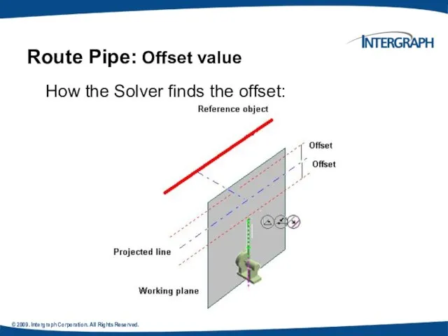
Route Pipe: Offset value
How the
© 2009. Intergraph Corporation. All Rights Reserved.
Route Pipe: Offset value
How the
© 2004. Intergraph Corporation. All Rights Reserved.
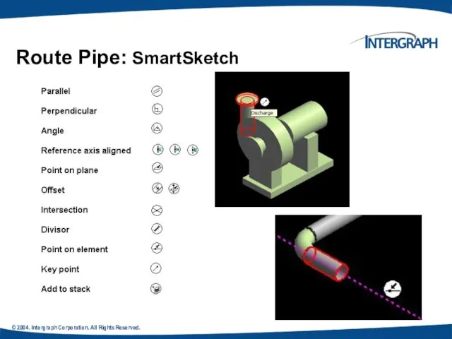
Route Pipe: SmartSketch
© 2004. Intergraph Corporation. All Rights Reserved.
Route Pipe: SmartSketch
© 2004. Intergraph Corporation. All Rights Reserved.
PinPoint provides coordinate inputs to
© 2004. Intergraph Corporation. All Rights Reserved.
PinPoint provides coordinate inputs to
© 2004. Intergraph Corporation. All Rights Reserved.
Angle lock in Route command
© 2004. Intergraph Corporation. All Rights Reserved.
Angle lock in Route command
© 2004. Intergraph Corporation. All Rights Reserved.
Route Pipe: Working Plane Control
© 2004. Intergraph Corporation. All Rights Reserved.
Route Pipe: Working Plane Control
© 2004. Intergraph Corporation. All Rights Reserved.
Pipe Select Command
Provides specific filters:
Workspace
© 2004. Intergraph Corporation. All Rights Reserved.
Pipe Select Command
Provides specific filters:
Workspace
© 2004. Intergraph Corporation. All Rights Reserved.
Deleting a pipeline deletes all
© 2004. Intergraph Corporation. All Rights Reserved.
Deleting a pipeline deletes all
© 2004. Intergraph Corporation. All Rights Reserved.
Deleting the run deletes all
© 2004. Intergraph Corporation. All Rights Reserved.
Deleting the run deletes all
© 2004. Intergraph Corporation. All Rights Reserved.
Example:
Delete Straight Features
© 2004. Intergraph Corporation. All Rights Reserved.
Example:
Delete Straight Features
© 2004. Intergraph Corporation. All Rights Reserved.
When you select an end
© 2004. Intergraph Corporation. All Rights Reserved.
When you select an end
© 2004. Intergraph Corporation. All Rights Reserved.
Routing To or From a
© 2004. Intergraph Corporation. All Rights Reserved.
Routing To or From a
© 2004. Intergraph Corporation. All Rights Reserved.
Insert Component
Insert command inserts a
© 2004. Intergraph Corporation. All Rights Reserved.
Insert Component
Insert command inserts a
© 2004. Intergraph Corporation. All Rights Reserved.
Insert Component :Insert Component Ribbon
© 2004. Intergraph Corporation. All Rights Reserved.
Insert Component :Insert Component Ribbon
© 2004. Intergraph Corporation. All Rights Reserved.
Insert Component : Graphical Positioning
© 2004. Intergraph Corporation. All Rights Reserved.
Insert Component : Graphical Positioning
© 2004. Intergraph Corporation. All Rights Reserved.
Insert Component : Graphical Positioning
Flip
© 2004. Intergraph Corporation. All Rights Reserved.
Insert Component : Graphical Positioning
Flip
© 2004. Intergraph Corporation. All Rights Reserved.
Insert Component : Mating
Mating part
© 2004. Intergraph Corporation. All Rights Reserved.
Insert Component : Mating
Mating part
© 2009. Intergraph Corporation. All Rights Reserved.
Insert Component : Positioning &
© 2009. Intergraph Corporation. All Rights Reserved.
Insert Component : Positioning &
© 2009. Intergraph Corporation. All Rights Reserved.
Routing Sloped Pipe
Underground piping collects
© 2009. Intergraph Corporation. All Rights Reserved.
Routing Sloped Pipe
Underground piping collects
© 2009. Intergraph Corporation. All Rights Reserved.
Slope format
Routing Sloped Pipe
© 2009. Intergraph Corporation. All Rights Reserved.
Slope format
Routing Sloped Pipe
© 2004. Intergraph Corporation. All Rights Reserved.
Routing Sloped Pipe
Specify Slope on
© 2004. Intergraph Corporation. All Rights Reserved.
Routing Sloped Pipe
Specify Slope on
© 2009. Intergraph Corporation. All Rights Reserved.
Routing Sloped Pipe: Slope Direction
© 2009. Intergraph Corporation. All Rights Reserved.
Routing Sloped Pipe: Slope Direction
© 2009. Intergraph Corporation. All Rights Reserved.
Reserved.
Modification of the “Slope” value
© 2009. Intergraph Corporation. All Rights Reserved.
Reserved.
Modification of the “Slope” value
© 2009. Intergraph Corporation. All Rights Reserved.
Routing Sloped Pipe :Angle Control
© 2009. Intergraph Corporation. All Rights Reserved.
Routing Sloped Pipe :Angle Control
© 2009. Intergraph Corporation. All Rights Reserved.
Piping Practice Labs
Route Pipes
Inserting Components
© 2009. Intergraph Corporation. All Rights Reserved.
Piping Practice Labs
Route Pipes
Inserting Components
© 2009. Intergraph Corporation. All Rights Reserved.
Integrated Environment
While designing or
© 2009. Intergraph Corporation. All Rights Reserved.
Integrated Environment
While designing or
© 2004. Intergraph Corporation. All Rights Reserved.
Retrieving Data from a P&ID
© 2004. Intergraph Corporation. All Rights Reserved.
Retrieving Data from a P&ID
© 2004. Intergraph Corporation. All Rights Reserved.
SP3D Routing From P&ID
Users can
© 2004. Intergraph Corporation. All Rights Reserved.
SP3D Routing From P&ID
Users can
© 2009. Intergraph Corporation. All Rights Reserved.
The engineering tag will be
© 2009. Intergraph Corporation. All Rights Reserved.
The engineering tag will be
© 2009. Intergraph Corporation. All Rights Reserved.
Instrument & Piping Specialty Placement
We
© 2009. Intergraph Corporation. All Rights Reserved.
Instrument & Piping Specialty Placement
We
© 2009. Intergraph Corporation. All Rights Reserved.
Instrument & Piping Specialty Placement
Placing
© 2009. Intergraph Corporation. All Rights Reserved.
Instrument & Piping Specialty Placement
Placing
© 2009. Intergraph Corporation. All Rights Reserved.
Instruments
Placement of Instrument Items On
© 2009. Intergraph Corporation. All Rights Reserved.
Instruments
Placement of Instrument Items On
© 2009. Intergraph Corporation. All Rights Reserved.
Placement of Instrument Items On
© 2009. Intergraph Corporation. All Rights Reserved.
Placement of Instrument Items On
© 2009. Intergraph Corporation. All Rights Reserved.
Placing Piping Specialty Items
Specialty items
© 2009. Intergraph Corporation. All Rights Reserved.
Placing Piping Specialty Items
Specialty items
© 2004. Intergraph Corporation. All Rights Reserved.
Piping Specialty Items Types
Stock specialty
© 2004. Intergraph Corporation. All Rights Reserved.
Piping Specialty Items Types
Stock specialty
© 2009. Intergraph Corporation. All Rights Reserved.
Placing Piping Specialty Items: Properties
Placement
© 2009. Intergraph Corporation. All Rights Reserved.
Placing Piping Specialty Items: Properties
Placement
© 2009. Intergraph Corporation. All Rights Reserved.
Insert Tap
Use this command when
© 2009. Intergraph Corporation. All Rights Reserved.
Insert Tap
Use this command when
© 2009. Intergraph Corporation. All Rights Reserved.
Inserting Splits : Insert Split
© 2009. Intergraph Corporation. All Rights Reserved.
Inserting Splits : Insert Split
© 2009. Intergraph Corporation. All Rights Reserved.
Inserting Splits : Insert Split
© 2009. Intergraph Corporation. All Rights Reserved.
Inserting Splits : Insert Split
© 2009. Intergraph Corporation. All Rights Reserved.
Inserting Splits : Attribute Break
© 2009. Intergraph Corporation. All Rights Reserved.
Inserting Splits : Attribute Break
© 2009. Intergraph Corporation. All Rights Reserved.
.
Edit Pipe Run properties during
© 2009. Intergraph Corporation. All Rights Reserved.
.
Edit Pipe Run properties during
© 2009. Intergraph Corporation. All Rights Reserved.
Routing Pipes from P&ID
Placing
© 2009. Intergraph Corporation. All Rights Reserved.
Routing Pipes from P&ID
Placing
© 2009. Intergraph Corporation. All Rights Reserved.
Piping Manipulation : Edit Straight
© 2009. Intergraph Corporation. All Rights Reserved.
Piping Manipulation : Edit Straight
© 2009. Intergraph Corporation. All Rights Reserved.
Piping Manipulation : Edit End
© 2009. Intergraph Corporation. All Rights Reserved.
Piping Manipulation : Edit End
© 2009. Intergraph Corporation. All Rights Reserved.
Piping Manipulation : Edit Run
© 2009. Intergraph Corporation. All Rights Reserved.
Piping Manipulation : Edit Run
© 2004. Intergraph Corporation. All Rights Reserved.
Piping Manipulation : Editing Features
Shift
© 2004. Intergraph Corporation. All Rights Reserved.
Piping Manipulation : Editing Features
Shift
© 2009. Intergraph Corporation. All Rights Reserved.
Piping Manipulation : Editing Features
Shift
© 2009. Intergraph Corporation. All Rights Reserved.
Piping Manipulation : Editing Features
Shift
© 2009. Intergraph Corporation. All Rights Reserved.
Piping Manipulation : Editing Features
Shift
© 2009. Intergraph Corporation. All Rights Reserved.
Piping Manipulation : Editing Features
Shift
© 2009. Intergraph Corporation. All Rights Reserved.
Mating parts can be changed
© 2009. Intergraph Corporation. All Rights Reserved.
Mating parts can be changed
© 2009. Intergraph Corporation. All Rights Reserved.
Operator may replace item with
© 2009. Intergraph Corporation. All Rights Reserved.
Operator may replace item with
© 2009. Intergraph Corporation. All Rights Reserved.
.
New Enhancement in V4
Ability
© 2009. Intergraph Corporation. All Rights Reserved.
.
New Enhancement in V4
Ability
© 2009. Intergraph Corporation. All Rights Reserved.
New Enhancement in V4
Copy/Paste
© 2009. Intergraph Corporation. All Rights Reserved.
New Enhancement in V4
Copy/Paste
© 2009. Intergraph Corporation. All Rights Reserved.
Right clicking on pipe run
© 2009. Intergraph Corporation. All Rights Reserved.
Right clicking on pipe run
© 2009. Intergraph Corporation. All Rights Reserved.
.
Piping Properties :Edit Properties Command
Edit
© 2009. Intergraph Corporation. All Rights Reserved.
.
Piping Properties :Edit Properties Command
Edit
© 2009. Intergraph Corporation. All Rights Reserved.
Piping Properties : Flow Direction
Flow
© 2009. Intergraph Corporation. All Rights Reserved.
Piping Properties : Flow Direction
Flow
© 2009. Intergraph Corporation. All Rights Reserved.
Piping Properties : Edit Properties
© 2009. Intergraph Corporation. All Rights Reserved.
Piping Properties : Edit Properties
© 2009. Intergraph Corporation. All Rights Reserved.
Piping Properties : Edit Properties
© 2009. Intergraph Corporation. All Rights Reserved.
Piping Properties : Edit Properties
© 2009. Intergraph Corporation. All Rights Reserved.
Pipe cut lengths to reflect
© 2009. Intergraph Corporation. All Rights Reserved.
Pipe cut lengths to reflect
© 2009. Intergraph Corporation. All Rights Reserved.
Ability to insert notes on
© 2009. Intergraph Corporation. All Rights Reserved.
Ability to insert notes on
© 2009. Intergraph Corporation. All Rights Reserved.
Creating Spools
Generation of Spools
Generate Spools
© 2009. Intergraph Corporation. All Rights Reserved.
Creating Spools
Generation of Spools
Generate Spools
© 2009. Intergraph Corporation. All Rights Reserved.
Generation of Spools
Create Penetration
© 2009. Intergraph Corporation. All Rights Reserved.
Generation of Spools
Create Penetration
© 2009. Intergraph Corporation. All Rights Reserved.
Naming of Spools
Spooling options
© 2009. Intergraph Corporation. All Rights Reserved.
Naming of Spools
Spooling options
© 2009. Intergraph Corporation. All Rights Reserved.
Breaks at unions by system
Breaks
© 2009. Intergraph Corporation. All Rights Reserved.
Breaks at unions by system
Breaks
© 2009. Intergraph Corporation. All Rights Reserved.
.
Sequence Objects
Renames objects in the
© 2009. Intergraph Corporation. All Rights Reserved.
.
Sequence Objects
Renames objects in the
© 2004. Intergraph Corporation. All Rights Reserved.
Materials Reports
Users can easily extract
© 2004. Intergraph Corporation. All Rights Reserved.
Materials Reports
Users can easily extract
© 2004. Intergraph Corporation. All Rights Reserved.
Manipulating Piping Objects
Creating Spools
Sequencing Objects
Creating
© 2004. Intergraph Corporation. All Rights Reserved.
Manipulating Piping Objects
Creating Spools
Sequencing Objects
Creating
 AZORI_TRENDS_2022
 Весна, любовь и комплименты
 Пространство детского чтения
 Педагогика творчества
 20160329_master-klass_rol_vosklitsatelnyh_predlozheniy
 Альтернативные источники электроэнергии
 Компания НеМ.КА
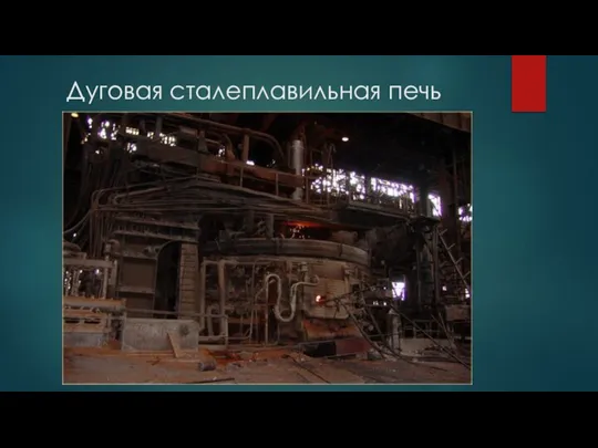 Дуговая сталеплавильная печь
 Общие понятия о зданиях и сооружениях требования, предъявляемые к зданиям (тема 4.1)
 Поршневой жидкостный насос
 Snezhinki-i-elka
 Тайное становится явным_ 2-й урок
 Wise men say
 Основные компоненты компьютера и их функции. Компьютер как унивесальное устройство для работы с информацией
 Архитектура CPLD MAX3000A фирмы Altera
 Задаём вопросы в диалоге
 Почему конструкции не ломаются
 Ремонт бытовых электроприборов
 Устройство кинопроектора
 Создание изделий из текстильных материалов
 Сланцевая революция и ее международно-политические последствия
 Системные решения для бассейнов с мозаикой
 Христианская семья
 Prezentatsia1
 Хоменко О.В
 20160120_demidova_v.i._litsey_no59
 Коммерческое общее уменьшенное
 553381