A tentative model of technology improvement in ferro- alloys manufacturing process & the business way forward
- A tentative model of technology improvement in ferro- alloys manufacturing process & the business way forward

Содержание
- 2. Chrome/ Manganese/Iron/Quartz Ore Producers Ferro Alloy Producers Steel Producers Fe Cr Fe Mn Si Mn/FeSi/FeSiCr Stainless/Carbon
- 3. Issues with Indian Ferro‐alloys Industry
- 4. VARIOUS CHALLENGES FACED BY THE INDIAN FERRO ALLOY INDUSTRY Power Captive Vs. Grid Raw Material Ore
- 5. MASTER PLAN FOR SURVIVAL DEPLETION OF HIGH-GRADE ORE Low grade beneficiation Agglomeration Sintering
- 7. Agglomeration & Productivity Improvement for Manganese alloy Investment in beneficiation & use of agglomerated feed •
- 8. Waste Heat Utilization & Raw material Handling Minimizing heat loss and use waste gases for power
- 9. MARCHING FOR CONSERVATION OF MINERAL
- 10. MARCHING FOR NEW INNOVATION Waste management of Manganese ore MnSO4 for agriculture
- 11. EXPERIMENT OBSERVATIONS FOR MANGANESE ORE SINTERING • Low yield with 100% belt spillage material for sintering.
- 12. Experiment Conclusion Raw material belt spillages can be sintered in combination with high grade Mn ore
- 13. IMAGES OF SINTERING PROCESS
- 14. IMAGES OF SINTERING PROCESS
- 15. IMAGES OF SINTERING PROCESS
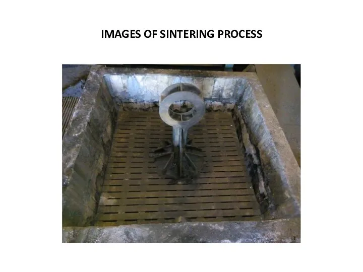
- 16. IMAGES OF SINTERING PROCESS
- 17. IMAGES OF SINTERING PROCESS
- 18. IMAGES OF SINTERING PROCESS
- 19. IMAGES OF SINTERING PROCESS
- 20. Agglomeration of Beneficiated Manganese Ore Fines SINTERING Micro‐Granulation is a required to sinter the beneficiated Mn
- 21. BRIQUETING • Mn ore briquettes were produced and trial conducted in different Ferro Alloys Plant. •
- 22. Mn‐ORE BENEFICIATION‐ NEW TECHNOLOGIES Physical Beneficiation a) Automatic Ore Sorter b) Electrostatic Separation c) Magnetic Flocculation
- 23. Mn‐ORE BENEFICIATION‐ NEW TECHNOLOGIES Pyrometallurgical Route • Magnetic Separation • Reduction Roasting
- 24. Mn‐ORE BENEFICIATION‐ NEW TECHNOLOGIES Hydrometallurgical Methods Leaching : Reducing agents natural gases, oxalic acid, methanol, carbohydrate,
- 26. PROCEDURES AT FERRO MANGANESE PLANT
- 27. OUTOTEC PROCESS
- 28. ENERGY EFFICIENT PROCESS FOR PALLETISING AND SINTERING
- 29. PREHEATING OF THE CHARGE
- 30. SEALED SUBMERGED-ARC FURNACE
- 31. POWER CONSUMPTION IN SMELTING
- 32. PROCESS IMPROVEMENTS TOWARDS MINERAL CONSERVATION • Wide variation in the low grade Chrome Ore Quality -
- 33. IMPROVEMENT JOURNEY IN BENEFICIATION OF CHROME ORE FOR BETTER MINERAL CONSERVATION OBJECTIVES Economic Use of Mineral
- 34. BRIQUETTING OF CHROMITES ORE In developing a technology for briquetting of chrome ores, it is important
- 35. LAYOUT MODIFICATION OF BRIQUETTE PLANT Briquette plant should be set of at back site of furnace
- 36. Briquette stacking design should be taken in such a concrete platform that each lot having conical
- 37. CHUTE TUBE FILLING PATTERN Alternate chute tube should be filled with charge always which will give
- 38. DESIGN OF POLLUTION PLANT Furnace generated flue gas through chimney ducting to pollution plant-bag filters-pollution stack
- 39. FURNACE OPERATIONAL POINT OF VIEW Required charge level in furnace hearth. Required electrode length as per
- 40. Increased heat efficiency by suitable selection of current and voltage ranges with proper electrode tip positioning(0.7-0.75
- 41. Proper permeability of charge material should be there to effectively utilize CO gas for reduction. For
- 42. If the Cr2O3 content in the ore is too high , some of the chromium oxide
- 43. Feed consists of temporarily bound fines with higher specific surface are which in turn leads to
- 44. Basicity of the slag should be maintained within the range 1.1-1.2 to have the easy separation
- 45. Hot alloy tapping should be taken with short runner with 2-nos CI- circular pan placing in
- 46. METAL HANDLING POINT OF VIEW At metal handling yard (adjacent to tapping bay),slag layer above the
- 47. Double jigging should be taken in same series after getting the tailings from two floating baths(one
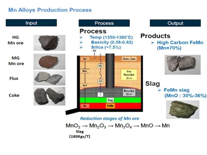
- 48. REDUCTION REACTION INSIDE FURNACE HEARTH MnO2 Mn2O3 MnO (Low oxidation statae) Mno + C = Mn
- 49. RATE OF SMELTING REACTION Solid- Gas reaction at (750-1000)degree centigrade Stability of material at hot bath
- 50. CONCLUSION Maximum portion of the income of Ferro-alloy manufacturers is taken away by electricity. Hence the
- 52. Скачать презентацию
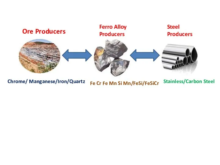
Chrome/ Manganese/Iron/Quartz
Ore Producers
Ferro Alloy
Producers
Steel
Producers
Fe Cr Fe Mn Si Mn/FeSi/FeSiCr
Stainless/Carbon Steel
Chrome/ Manganese/Iron/Quartz
Ore Producers
Ferro Alloy
Producers
Steel
Producers
Fe Cr Fe Mn Si Mn/FeSi/FeSiCr
Stainless/Carbon Steel
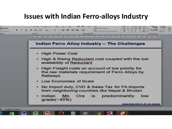
Issues with Indian Ferro‐alloys Industry
Issues with Indian Ferro‐alloys Industry
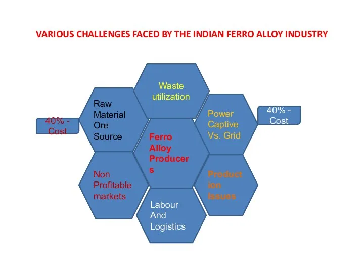
VARIOUS CHALLENGES FACED BY THE INDIAN FERRO ALLOY INDUSTRY
Power
Captive
Vs. Grid
Raw
Material
Ore Source
Non
Profitable
markets
Production
Issues
Waste
VARIOUS CHALLENGES FACED BY THE INDIAN FERRO ALLOY INDUSTRY
Power
Captive
Vs. Grid
Raw
Material
Ore Source
Non
Profitable
markets
Production
Issues
Waste
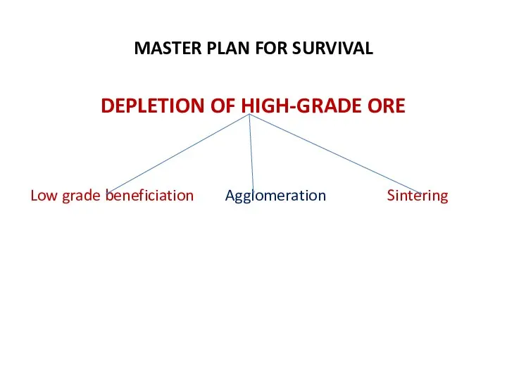
MASTER PLAN FOR SURVIVAL
DEPLETION OF HIGH-GRADE ORE
Low grade beneficiation Agglomeration Sintering
MASTER PLAN FOR SURVIVAL
DEPLETION OF HIGH-GRADE ORE
Low grade beneficiation Agglomeration Sintering

Agglomeration &
Productivity Improvement for Manganese alloy
Investment in beneficiation & use of
Agglomeration &
Productivity Improvement for Manganese alloy
Investment in beneficiation & use of
Waste Heat Utilization & Raw material Handling
Minimizing heat loss and use
Waste Heat Utilization & Raw material Handling
Minimizing heat loss and use
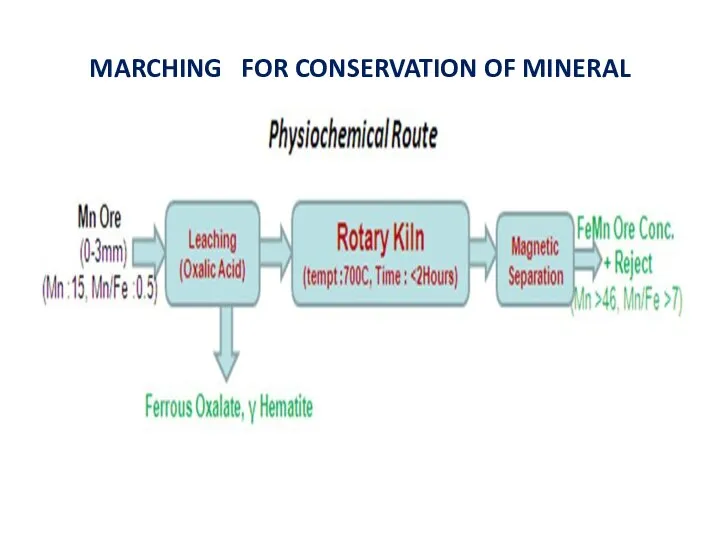
MARCHING FOR CONSERVATION OF MINERAL
MARCHING FOR CONSERVATION OF MINERAL
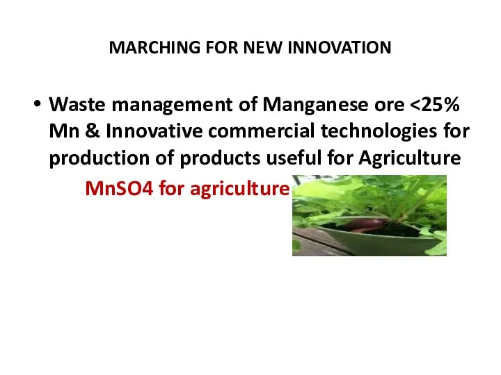
MARCHING FOR NEW INNOVATION
Waste management of Manganese ore <25% Mn &
MARCHING FOR NEW INNOVATION
Waste management of Manganese ore <25% Mn &
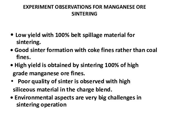
EXPERIMENT OBSERVATIONS FOR MANGANESE ORE SINTERING
• Low yield with 100% belt
EXPERIMENT OBSERVATIONS FOR MANGANESE ORE SINTERING
• Low yield with 100% belt
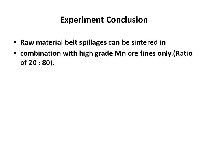
Experiment Conclusion
Raw material belt spillages can be sintered in
combination with high
Experiment Conclusion
Raw material belt spillages can be sintered in
combination with high
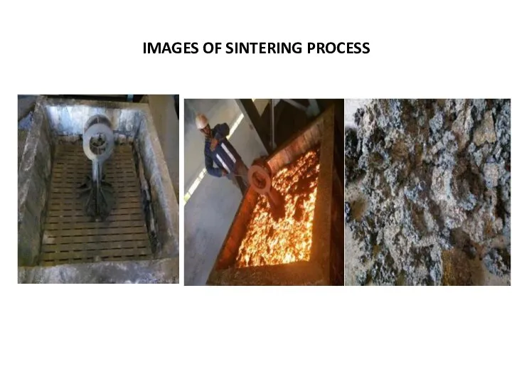
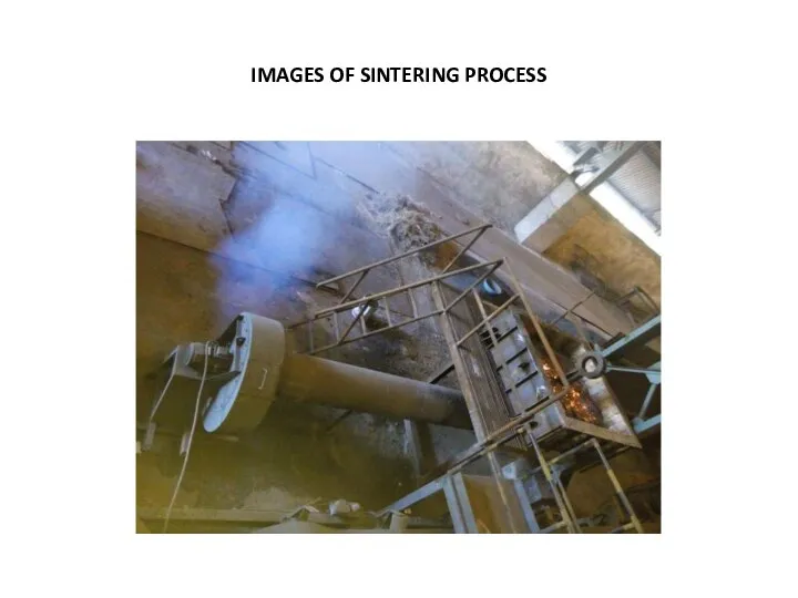
IMAGES OF SINTERING PROCESS
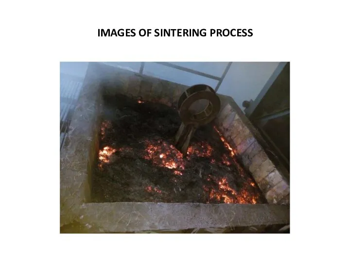
IMAGES OF SINTERING PROCESS
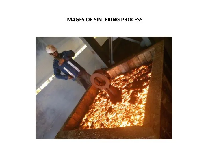
IMAGES OF SINTERING PROCESS
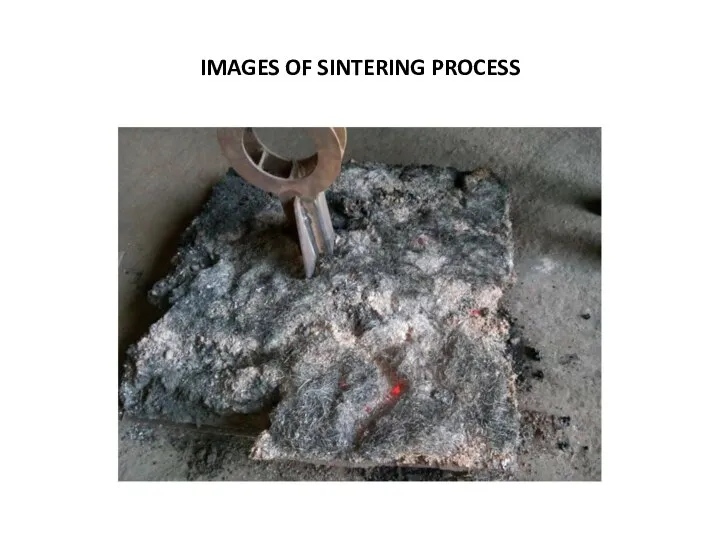
IMAGES OF SINTERING PROCESS
IMAGES OF SINTERING PROCESS
IMAGES OF SINTERING PROCESS
IMAGES OF SINTERING PROCESS
IMAGES OF SINTERING PROCESS
IMAGES OF SINTERING PROCESS
IMAGES OF SINTERING PROCESS
IMAGES OF SINTERING PROCESS
IMAGES OF SINTERING PROCESS
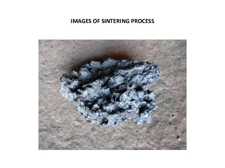
IMAGES OF SINTERING PROCESS
IMAGES OF SINTERING PROCESS
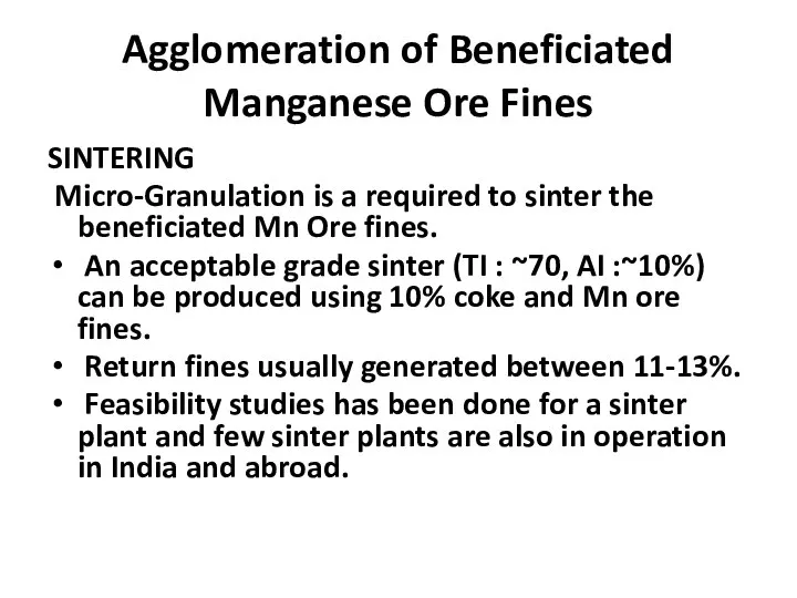
Agglomeration of Beneficiated Manganese Ore Fines
SINTERING
Micro‐Granulation is a required to
Agglomeration of Beneficiated Manganese Ore Fines
SINTERING
Micro‐Granulation is a required to
BRIQUETING
• Mn ore briquettes were produced and trial conducted in different
BRIQUETING
• Mn ore briquettes were produced and trial conducted in different
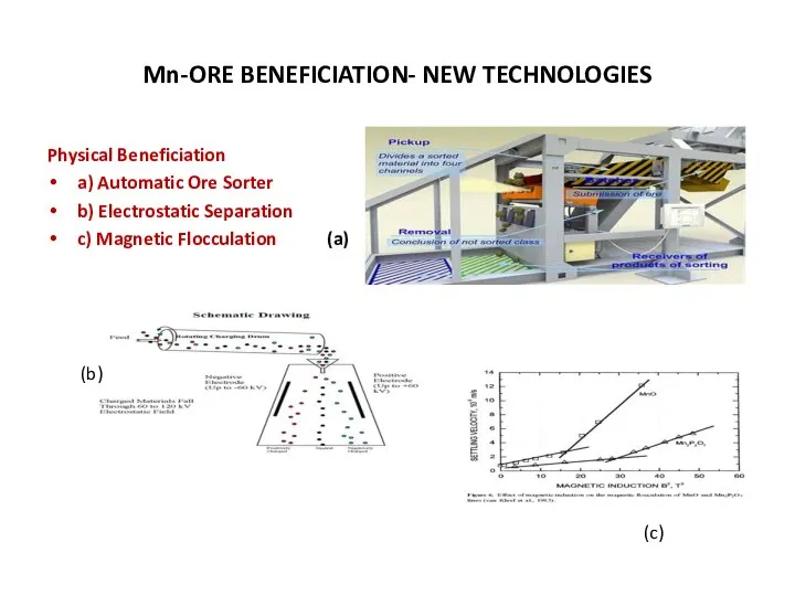
Mn‐ORE BENEFICIATION‐ NEW TECHNOLOGIES
Physical Beneficiation
a) Automatic Ore Sorter
b) Electrostatic Separation
c) Magnetic
Mn‐ORE BENEFICIATION‐ NEW TECHNOLOGIES
Physical Beneficiation
a) Automatic Ore Sorter
b) Electrostatic Separation
c) Magnetic
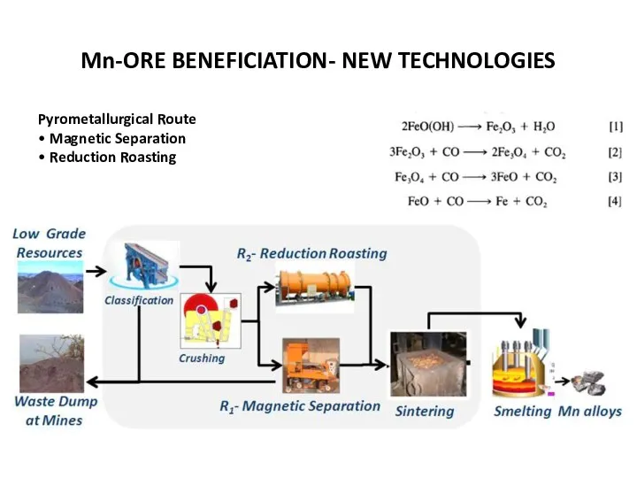
Mn‐ORE BENEFICIATION‐ NEW TECHNOLOGIES
Pyrometallurgical Route
• Magnetic Separation
• Reduction Roasting
Mn‐ORE BENEFICIATION‐ NEW TECHNOLOGIES
Pyrometallurgical Route
• Magnetic Separation
• Reduction Roasting
Mn‐ORE BENEFICIATION‐ NEW TECHNOLOGIES
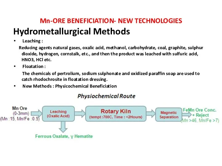
Hydrometallurgical Methods
Leaching :
Reducing agents natural gases,
Mn‐ORE BENEFICIATION‐ NEW TECHNOLOGIES
Hydrometallurgical Methods
Leaching :
Reducing agents natural gases,
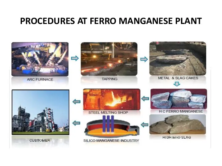
PROCEDURES AT FERRO MANGANESE PLANT
PROCEDURES AT FERRO MANGANESE PLANT
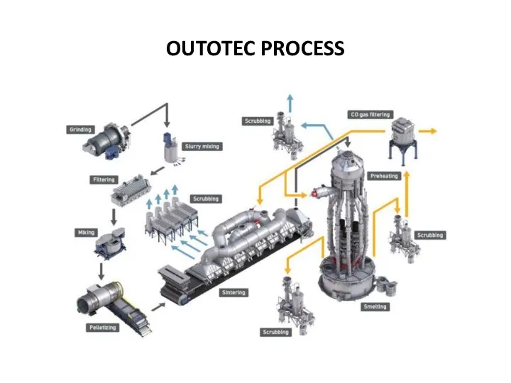
OUTOTEC PROCESS
OUTOTEC PROCESS
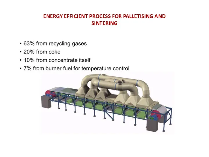
ENERGY EFFICIENT PROCESS FOR PALLETISING AND
SINTERING
ENERGY EFFICIENT PROCESS FOR PALLETISING AND
SINTERING
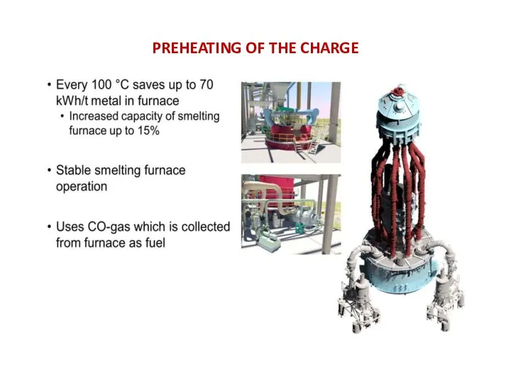
PREHEATING OF THE CHARGE
PREHEATING OF THE CHARGE
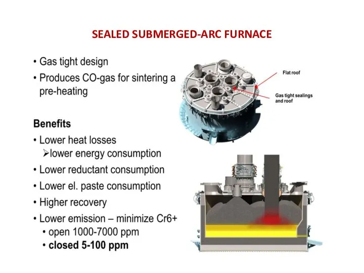
SEALED SUBMERGED-ARC FURNACE
SEALED SUBMERGED-ARC FURNACE
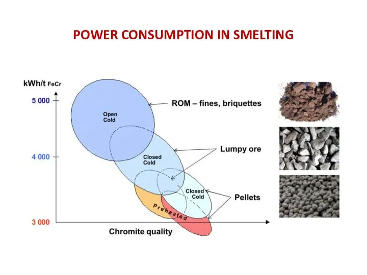
POWER CONSUMPTION IN SMELTING
POWER CONSUMPTION IN SMELTING
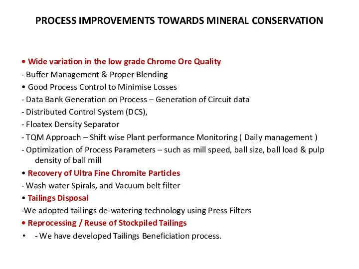
PROCESS IMPROVEMENTS TOWARDS MINERAL CONSERVATION
• Wide variation in the low grade
PROCESS IMPROVEMENTS TOWARDS MINERAL CONSERVATION
• Wide variation in the low grade
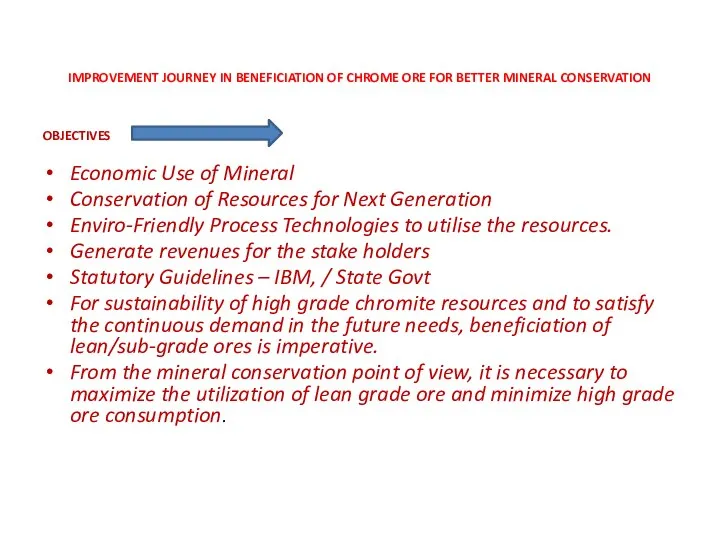
IMPROVEMENT JOURNEY IN BENEFICIATION OF CHROME ORE FOR BETTER MINERAL CONSERVATION
OBJECTIVES
IMPROVEMENT JOURNEY IN BENEFICIATION OF CHROME ORE FOR BETTER MINERAL CONSERVATION
OBJECTIVES
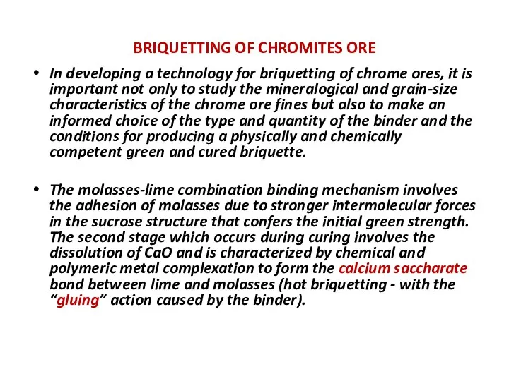
BRIQUETTING OF CHROMITES ORE
In developing a technology for briquetting of chrome
BRIQUETTING OF CHROMITES ORE
In developing a technology for briquetting of chrome
LAYOUT MODIFICATION OF BRIQUETTE PLANT
Briquette plant should be set of at
LAYOUT MODIFICATION OF BRIQUETTE PLANT
Briquette plant should be set of at
Briquette stacking design should be taken in such a concrete platform
Briquette stacking design should be taken in such a concrete platform
CHUTE TUBE FILLING PATTERN
Alternate chute tube should be filled with charge
CHUTE TUBE FILLING PATTERN
Alternate chute tube should be filled with charge
DESIGN OF POLLUTION PLANT
Furnace generated flue gas through chimney ducting to
DESIGN OF POLLUTION PLANT
Furnace generated flue gas through chimney ducting to
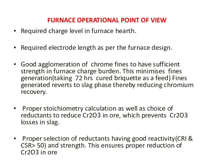
FURNACE OPERATIONAL POINT OF VIEW
Required charge level in furnace hearth.
Required electrode
FURNACE OPERATIONAL POINT OF VIEW
Required charge level in furnace hearth.
Required electrode
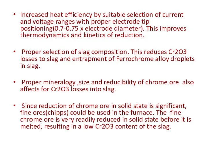
Increased heat efficiency by suitable selection of current and voltage ranges
Increased heat efficiency by suitable selection of current and voltage ranges
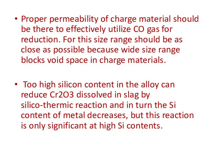
Proper permeability of charge material should be there to effectively utilize
Proper permeability of charge material should be there to effectively utilize
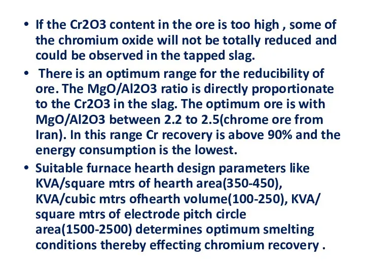
If the Cr2O3 content in the ore is too high ,
If the Cr2O3 content in the ore is too high ,
Feed consists of temporarily bound fines with higher specific surface are
Feed consists of temporarily bound fines with higher specific surface are
Basicity of the slag should be maintained within the range 1.1-1.2
Basicity of the slag should be maintained within the range 1.1-1.2
Hot alloy tapping should be taken with short runner with 2-nos
Hot alloy tapping should be taken with short runner with 2-nos
METAL HANDLING POINT OF VIEW
At metal handling yard (adjacent to tapping
METAL HANDLING POINT OF VIEW
At metal handling yard (adjacent to tapping
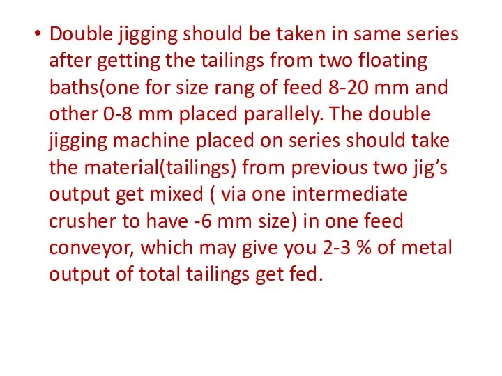
Double jigging should be taken in same series after getting the
Double jigging should be taken in same series after getting the
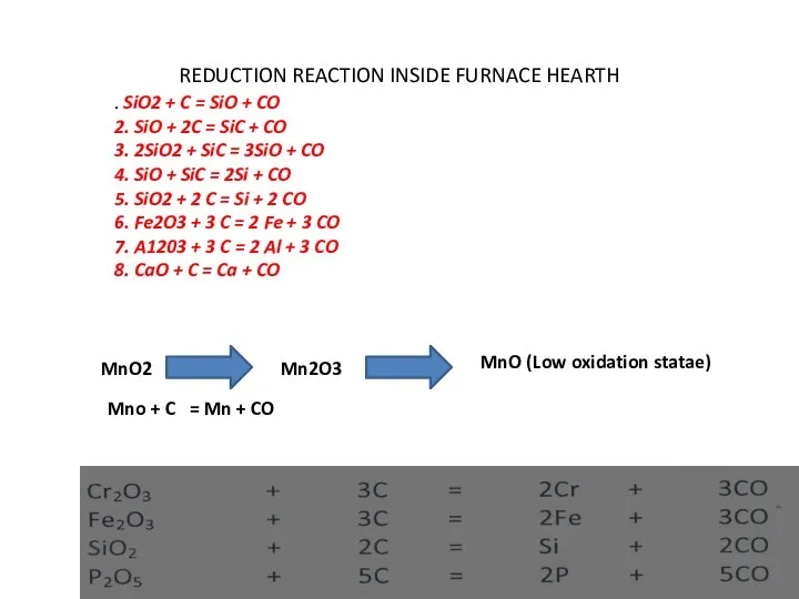
REDUCTION REACTION INSIDE FURNACE HEARTH
MnO2
Mn2O3
MnO (Low oxidation statae)
Mno + C
REDUCTION REACTION INSIDE FURNACE HEARTH
MnO2
Mn2O3
MnO (Low oxidation statae)
Mno + C
RATE OF SMELTING REACTION
Solid- Gas reaction at (750-1000)degree centigrade
Stability
RATE OF SMELTING REACTION
Solid- Gas reaction at (750-1000)degree centigrade
Stability
CONCLUSION
Maximum portion of the income of Ferro-alloy manufacturers is taken
CONCLUSION
Maximum portion of the income of Ferro-alloy manufacturers is taken
 ЕСТЕСТВОЗНАНИЕ И НКН НКН – целостная система взглядов и представлений на общие свойства и закономерности природы, выраженная в
 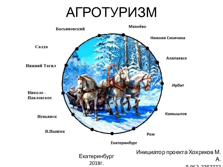 Агротуризм. Многофункциональный проект. ООО «Ясень»
 ММА. What is UFC
 Актуальные конференции
 Я люблю спорт
 Летняя практика. Часть 4. Массивы
 Платформа «Центр управления M2M»
 Презентация Маркетинговые исследования
 Силурийский период 443 млн.л.н. – 416 млн.л.н.
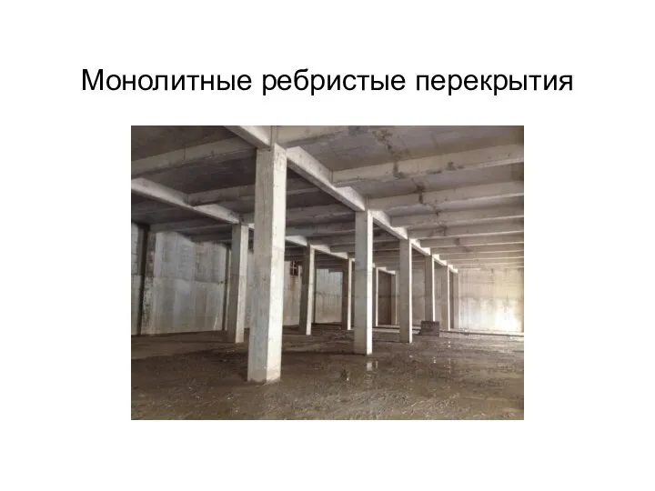 Монолитные ребристые перекрытия
 Тема 9. Бюджетная система
 Droga Krzyżowa z Janem Pawłem II
 Методология и методы педагогических исследований
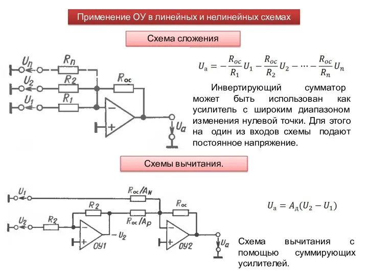 Применение ОУ в линейных и нелинейных схемах. СА1 лекция 7
 Формы и типы государств. Лекция № 3
 Программа «БОНУС-ЭКСПРЕС» Предложение для потенциальных потребителей
 Административная, военная, церковная, налоговая реформы Петра Великого
 Народы Норвегии
  Политический режим
 Сети центров общения «Надежда». Новый формат сотрудничества на условиях франчайзинга
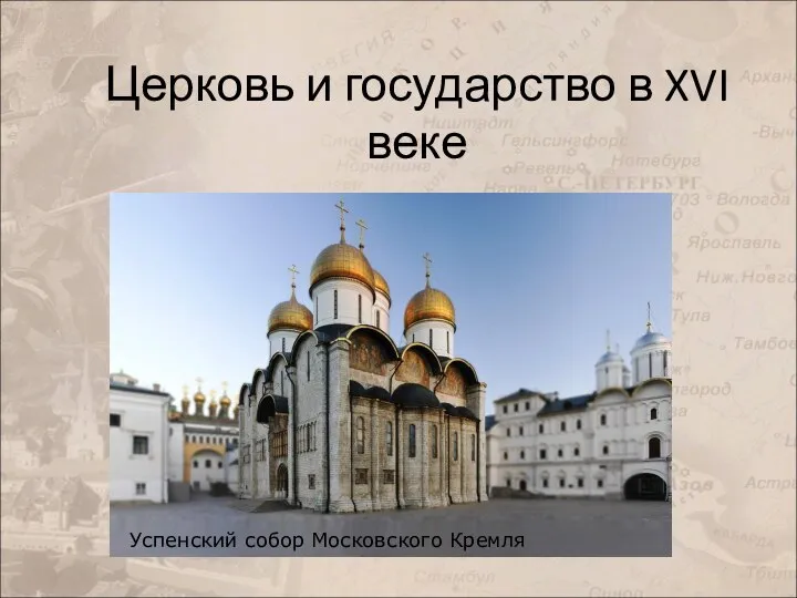 Церковь и государство в XVI веке
 Generic Collections Java Core
 Правовое положение учреждений Никитенко Екатерина Медянкин Павел
  Лингвистическая экспертиза
 Глюконеогенез
 Развитие программирования. Платформа .NET (C#, Лекция 1)
 Необходимость обучения плаванию в рамках занятий физической культурой
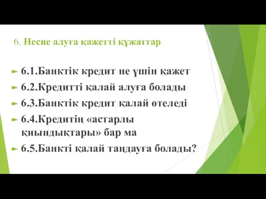 Несие алуға қажетті құжаттар