- HW Repair Guide SM-T310 (LT01)

Содержание
- 2. 1. All functionality, features, specifications and other product information provided in this document including, but not
- 3. Contents Introduction of LT01 Service Guide Boot Recovery Repair Guide Assembly & Disassembly Electronic Components SMD
- 4. Introduction of SM-T310 Specification Feature - 8” Display - Slim Design Tablet
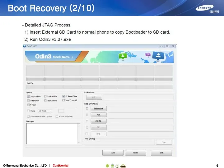
- 5. Boot Recovery (1/10) Brief JTAG process for SM-T310 1) Copying Bootloader File to external SD Card,
- 6. Boot Recovery (2/10)
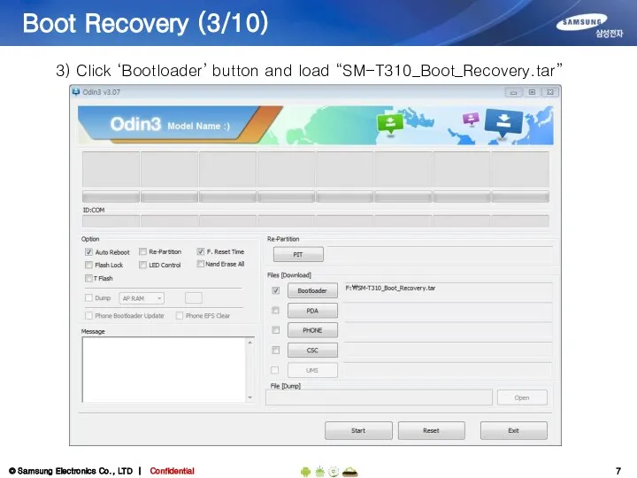
- 7. Boot Recovery (3/10) 3) Click ‘Bootloader’ button and load “SM-T310_Boot_Recovery.tar”
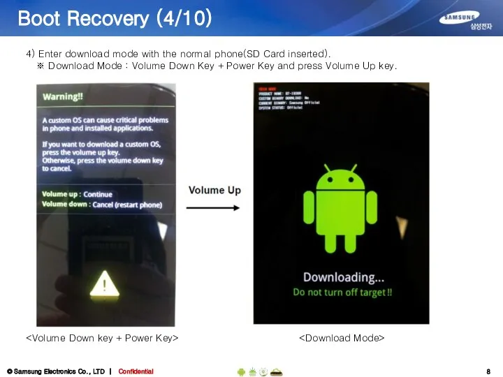
- 8. Boot Recovery (4/10) 4) Enter download mode with the normal phone(SD Card inserted). ※ Download Mode
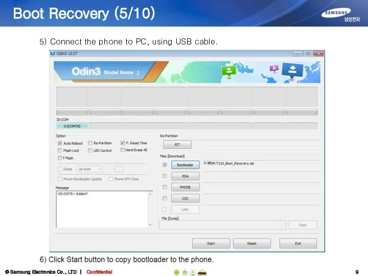
- 9. Boot Recovery (5/10) 5) Connect the phone to PC, using USB cable.
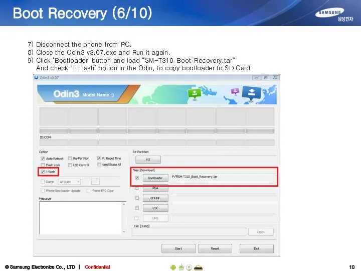
- 10. Boot Recovery (6/10) 7) Disconnect the phone from PC. 8) Close the Odin3 v3.07.exe and Run
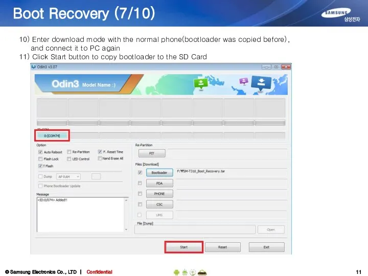
- 11. Boot Recovery (7/10) 10) Enter download mode with the normal phone(bootloader was copied before), and connect
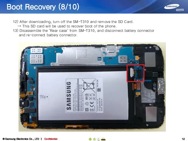
- 12. Boot Recovery (8/10) 12) After downloading, turn off the SM-T310 and remove the SD Card. →
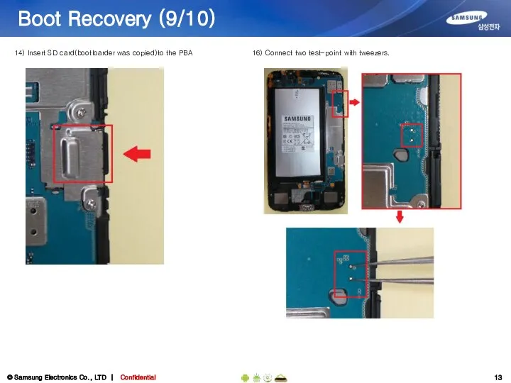
- 13. Boot Recovery (9/10) 14) Insert SD card(bootloarder was copied)to the PBA 16) Connect two test-point with
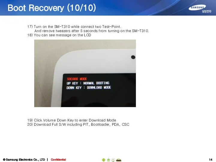
- 14. Boot Recovery (10/10) 17) Turn on the SM-T310 while connect two Test-Point. And remove tweezers after
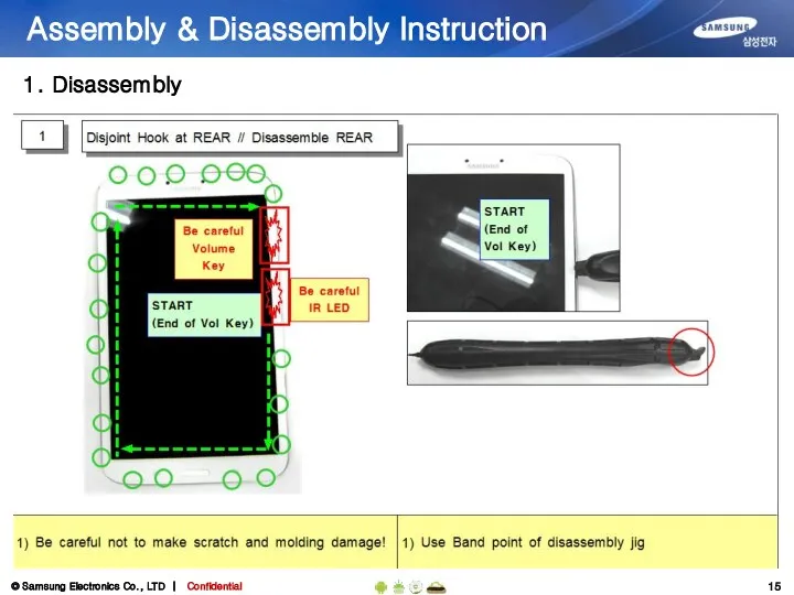
- 15. Assembly & Disassembly Instruction 1. Disassembly
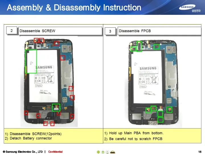
- 16. Assembly & Disassembly Instruction
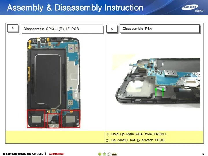
- 17. Assembly & Disassembly Instruction
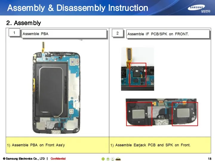
- 18. Assembly & Disassembly Instruction 2. Assembly
- 19. Assembly & Disassembly Instruction
- 20. Assembly & Disassembly Instruction
- 21. Electronic Components (1/2) GH96-06306A 5M CAMERA GH59-13346A MIC Power Key Volume Key Ir LED GH96-06319A Right
- 22. Electronic Components (2/2) LCD TSP Assy GH96-06467A TSP Connector LCD Connector Home Key FPCB GH59-13343A
- 23. SMD parts (TOP side) HDC202 3711-007738 Earjack FPCB Connector SOC300 3709-001811 SD Card Socket HDC602 3711-006925
- 24. SMD parts (Bottom side) HDC600 3708-002222 5M Camera Connector ANT100, ANT101 3712-001473 Antenna Contact (BT, Wifi,
- 25. Power problem
- 26. Power problem Step5 Step6 U500 C523 C532 C521 C524 AP_PS_HOLD(TP) C705 OSC700
- 27. Charging
- 28. Charging Step2, 3 C304 U502
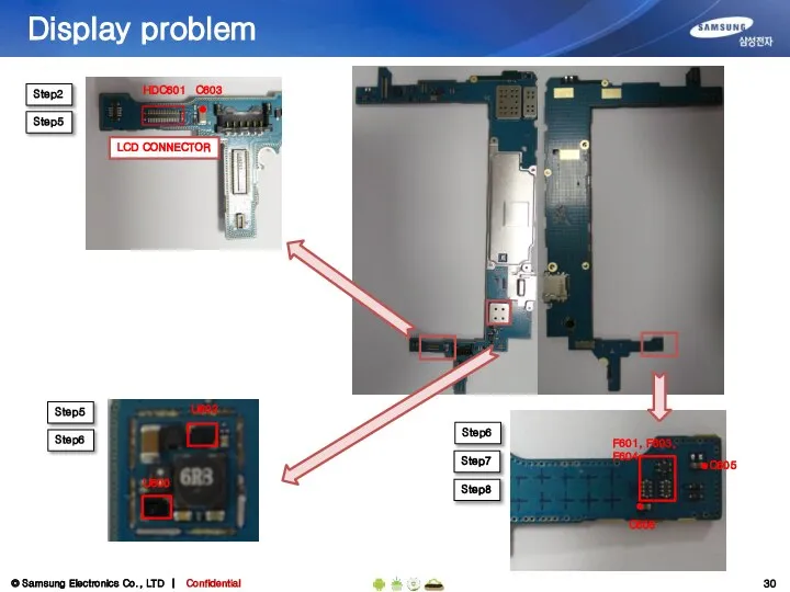
- 29. Display problem
- 30. Display problem Step5 Step6 C606 C605 F601, F603, F604 Step2 Step5 Step7 Step8 Step5 Step6
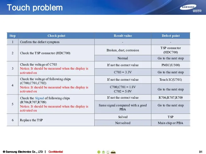
- 31. Touch problem
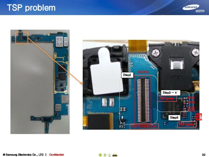
- 32. TSP problem Step2 Step3 ~ 4 HDC700 C701 C703 R906 R907 TSP CONNECTOR TSP signal TSP
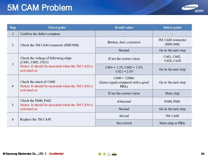
- 33. 5M CAM Problem
- 34. 5M CAM Problem F602 F600 C601 C602 HDC600 C621 C600
- 35. 1.3M CAM Problem
- 36. 1.3M CAM Problem F605 HDC602 C614 C612 C613 C609
- 37. Speaker problem
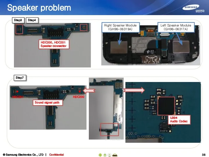
- 38. Speaker problem Step3 HDC200 Step7 HDC200, HDC201 Speaker connector HDC201 U204 Audio Codec Step4 Left Speaker
- 39. Earphone problem
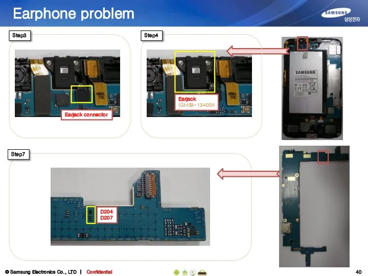
- 40. Earphone problem Step3 Step7 Earjack connector Step4 Earjack (GH59-13405A) D204 D207
- 41. Microphone problem
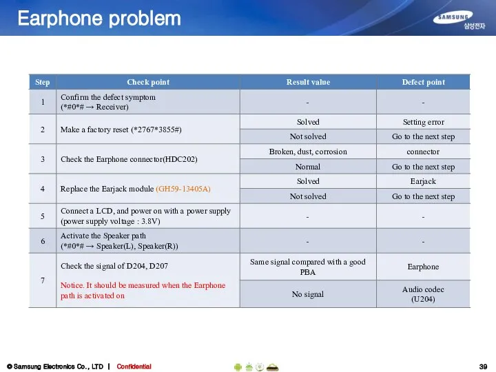
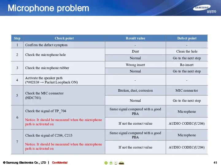
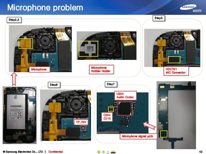
- 42. Microphone problem Step2,3 Microphone Microphone Rubber Holder TP_704 Step6 Microphone signal path Step5 HDC701 MIC Connector
- 43. BT/WIFI Problem
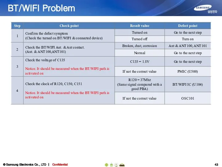
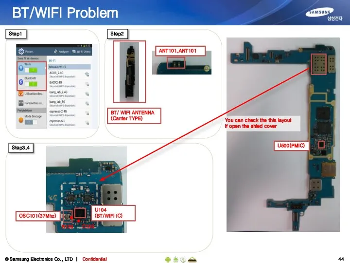
- 44. U104 (BT/WIFI IC) BT/WIFI Problem Step1 Step3,4 C135 OSC101(37Mhz) U500(PMIC) You can check the this layout
- 45. GPS/GLONASS Problem
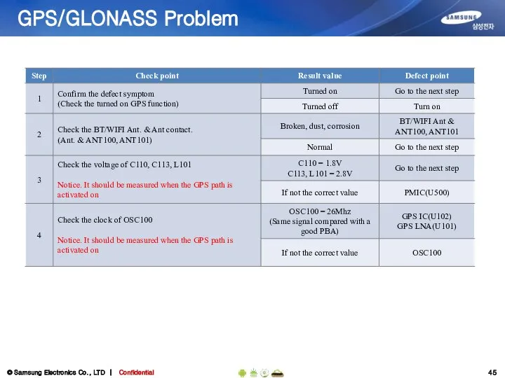
- 46. U102(GPS IC) GPS/GLONASS Problem Step1 Step3,4 L101 OSC100(26Mhz) U500(PMIC) You can check the this layout if
- 48. Скачать презентацию
1. All functionality, features, specifications and other product
information provided in this document including, but not limited
to, the benefits, design, pricing, components, performance,
availability, and capabilities of the product are subject to change
without notice or obligation. Samsung reserves the right to make changes to this document and the product described herein, at anytime, without obligation on Samsung to provide notification of such change.
2. In data
Contents
Introduction of LT01
Service Guide
Boot Recovery
Repair Guide
Assembly & Disassembly
Electronic Components
SMD parts
Trouble Shooting
Q&A
Contents
Introduction of LT01
Service Guide
Boot Recovery
Repair Guide
Assembly & Disassembly
Electronic Components
SMD parts
Trouble Shooting
Q&A
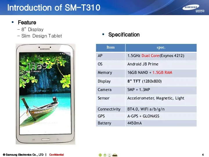
Introduction of SM-T310
Specification
Feature
- 8” Display
- Slim Design Tablet
Introduction of SM-T310
Specification
Feature
- 8” Display
- Slim Design Tablet
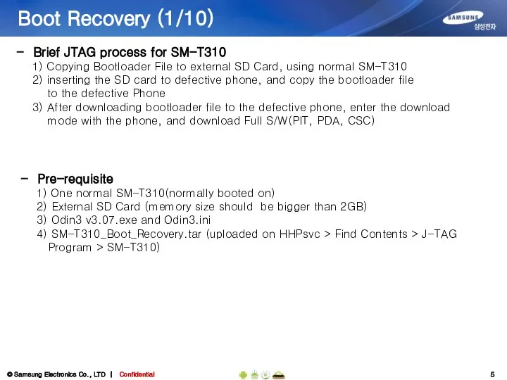
Boot Recovery (1/10)
Brief JTAG process for SM-T310
1) Copying Bootloader File
Boot Recovery (1/10)
Brief JTAG process for SM-T310
1) Copying Bootloader File
Boot Recovery (2/10)
Boot Recovery (2/10)
Boot Recovery (3/10)
3) Click ‘Bootloader’ button and load “SM-T310_Boot_Recovery.tar”
Boot Recovery (3/10)
3) Click ‘Bootloader’ button and load “SM-T310_Boot_Recovery.tar”
Boot Recovery (4/10)
4) Enter download mode with the normal phone(SD Card
Boot Recovery (4/10)
4) Enter download mode with the normal phone(SD Card
Boot Recovery (5/10)
5) Connect the phone to PC, using USB cable.
Boot Recovery (5/10)
5) Connect the phone to PC, using USB cable.
Boot Recovery (6/10)
7) Disconnect the phone from PC.
8) Close the Odin3
Boot Recovery (6/10)
7) Disconnect the phone from PC.
8) Close the Odin3
Boot Recovery (7/10)
10) Enter download mode with the normal phone(bootloader was
Boot Recovery (7/10)
10) Enter download mode with the normal phone(bootloader was
Boot Recovery (8/10)
12) After downloading, turn off the SM-T310 and remove
Boot Recovery (8/10)
12) After downloading, turn off the SM-T310 and remove
Boot Recovery (9/10)
14) Insert SD card(bootloarder was copied)to the PBA
16) Connect
Boot Recovery (9/10)
14) Insert SD card(bootloarder was copied)to the PBA
16) Connect
Boot Recovery (10/10)
17) Turn on the SM-T310 while connect two Test-Point.
Boot Recovery (10/10)
17) Turn on the SM-T310 while connect two Test-Point.
Assembly & Disassembly Instruction
1. Disassembly
Assembly & Disassembly Instruction
1. Disassembly
Assembly & Disassembly Instruction
Assembly & Disassembly Instruction
Assembly & Disassembly Instruction
Assembly & Disassembly Instruction
Assembly & Disassembly Instruction
2. Assembly
Assembly & Disassembly Instruction
2. Assembly
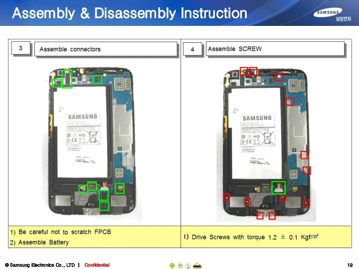
Assembly & Disassembly Instruction
Assembly & Disassembly Instruction
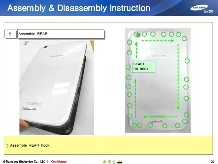
Assembly & Disassembly Instruction
Assembly & Disassembly Instruction
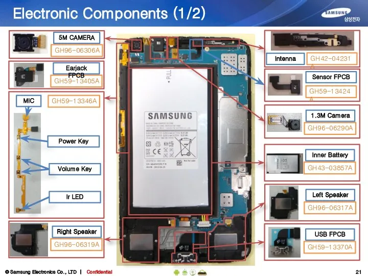
Electronic Components (1/2)
GH96-06306A
5M CAMERA
GH59-13346A
MIC
Power Key
Volume Key
Ir LED
GH96-06319A
Right Speaker
GH96-06317A
Left Speaker
GH59-13370A
USB FPCB
GH43-03857A
Inner Battery
GH42-04231A
Intenna
GH59-13424A
Sensor
Electronic Components (1/2)
GH96-06306A
5M CAMERA
GH59-13346A
MIC
Power Key
Volume Key
Ir LED
GH96-06319A
Right Speaker
GH96-06317A
Left Speaker
GH59-13370A
USB FPCB
GH43-03857A
Inner Battery
GH42-04231A
Intenna
GH59-13424A
Sensor
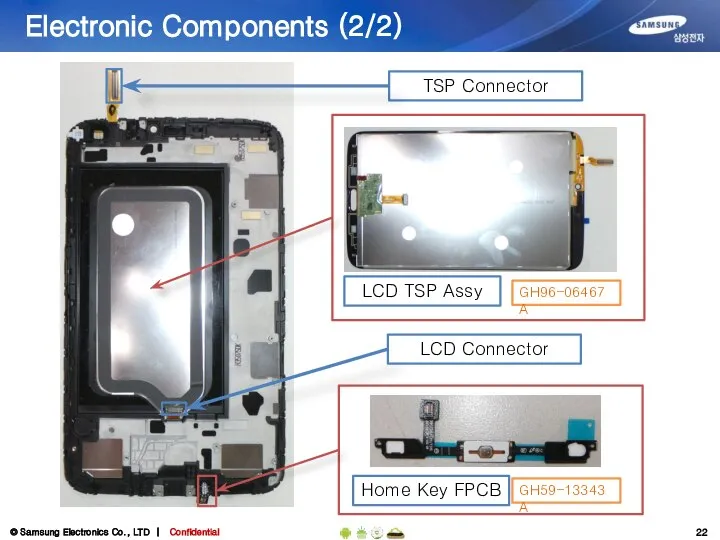
Electronic Components (2/2)
LCD TSP Assy
GH96-06467A
TSP Connector
LCD Connector
Home Key FPCB
GH59-13343A
Electronic Components (2/2)
LCD TSP Assy
GH96-06467A
TSP Connector
LCD Connector
Home Key FPCB
GH59-13343A
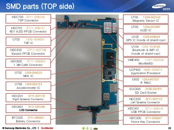
SMD parts (TOP side)
HDC202 3711-007738
Earjack FPCB Connector
SOC300 3709-001811
SD Card Socket
HDC602 3711-006925
1.3M
SMD parts (TOP side)
HDC202 3711-007738
Earjack FPCB Connector
SOC300 3709-001811
SD Card Socket
HDC602 3711-006925
1.3M
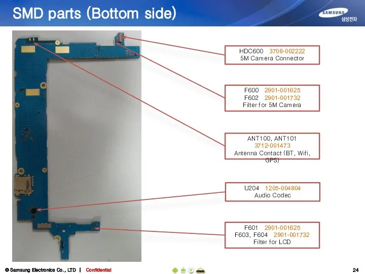
SMD parts (Bottom side)
HDC600 3708-002222
5M Camera Connector
ANT100, ANT101
3712-001473
Antenna Contact (BT, Wifi,
SMD parts (Bottom side)
HDC600 3708-002222
5M Camera Connector
ANT100, ANT101
3712-001473
Antenna Contact (BT, Wifi,
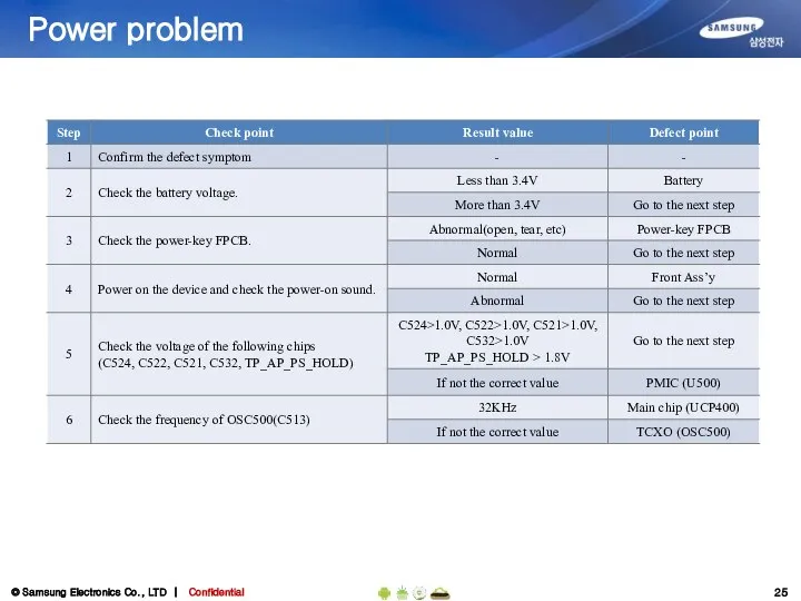
Power problem
Power problem
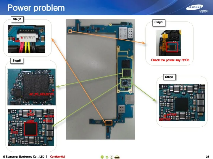
Power problem
Step5
Step6
U500
C523
C532
C521
C524
AP_PS_HOLD(TP)
C705
OSC700
Power problem
Step5
Step6
U500
C523
C532
C521
C524
AP_PS_HOLD(TP)
C705
OSC700
Charging
Charging
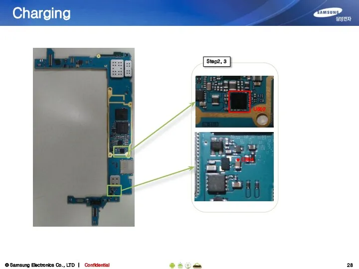
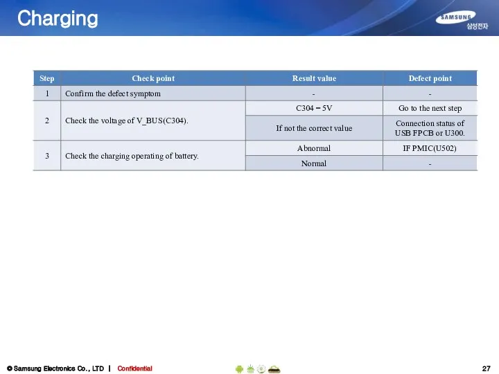
Charging
Step2, 3
C304
U502
Charging
Step2, 3
C304
U502
Display problem
Display problem
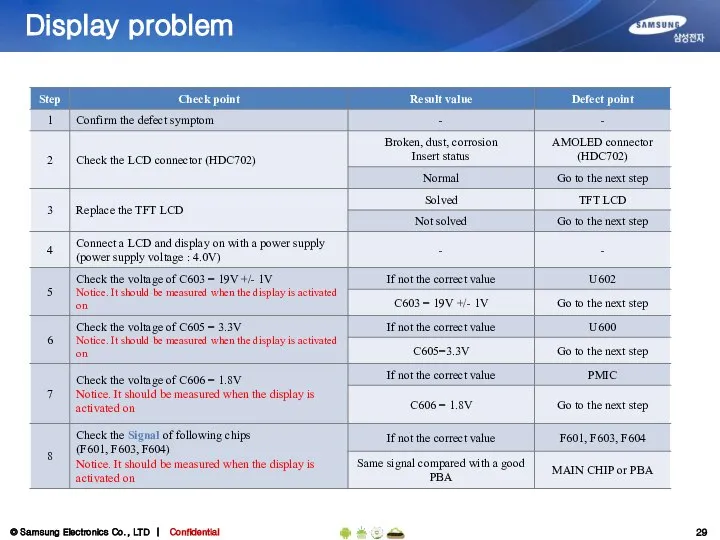
Display problem
Step5
Step6
C606
C605
F601, F603, F604
Step2
Step5
Step7
Step8
Step5
Step6
Display problem
Step5
Step6
C606
C605
F601, F603, F604
Step2
Step5
Step7
Step8
Step5
Step6
Touch problem
Touch problem
TSP problem
Step2
Step3 ~ 4
HDC700
C701
C703
R906
R907
TSP CONNECTOR
TSP signal
TSP power
Step5
C700
C702
R909
TSP problem
Step2
Step3 ~ 4
HDC700
C701
C703
R906
R907
TSP CONNECTOR
TSP signal
TSP power
Step5
C700
C702
R909
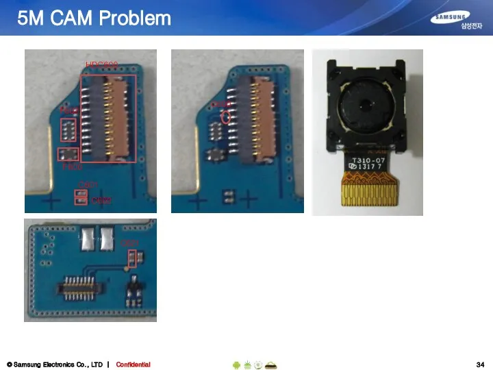
5M CAM Problem
5M CAM Problem
5M CAM Problem
F602
F600
C601
C602
HDC600
C621
C600
5M CAM Problem
F602
F600
C601
C602
HDC600
C621
C600
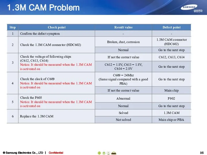
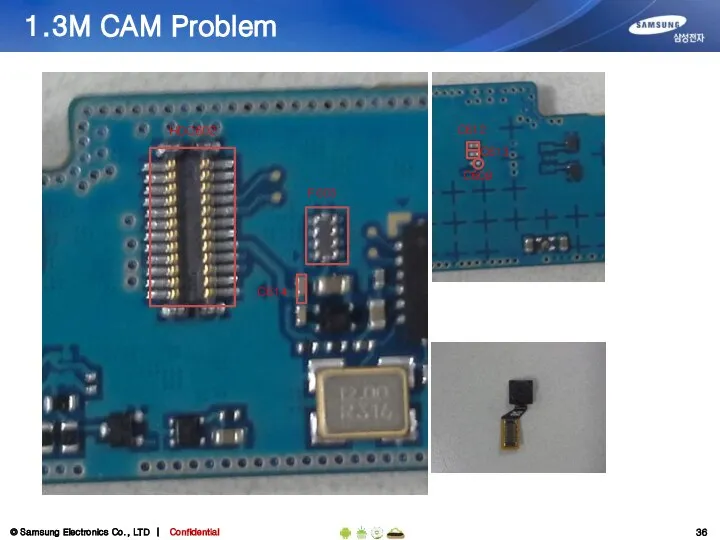
1.3M CAM Problem
1.3M CAM Problem
1.3M CAM Problem
F605
HDC602
C614
C612
C613
C609
1.3M CAM Problem
F605
HDC602
C614
C612
C613
C609
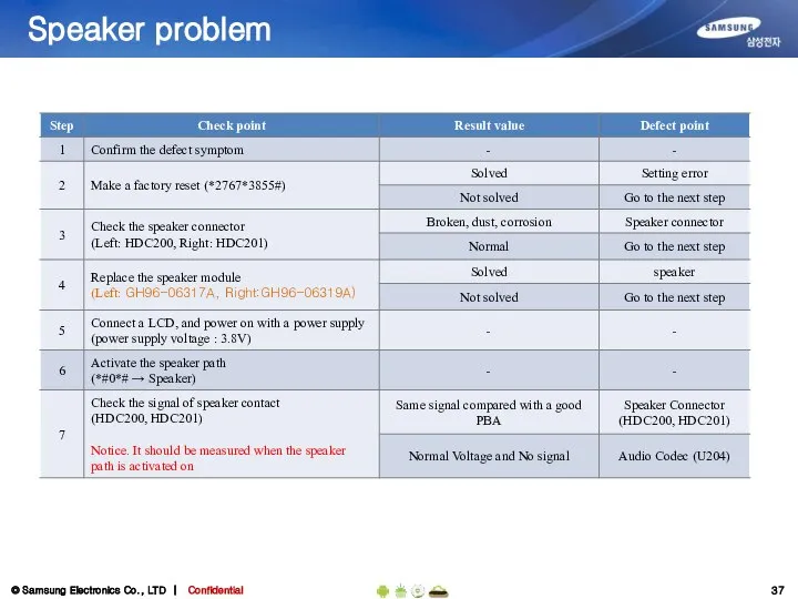
Speaker problem
Speaker problem
Speaker problem
Step3
HDC200
Step7
HDC200, HDC201
Speaker connector
HDC201
U204
Audio Codec
Step4
Left Speaker Module
(GH96-06317A)
Right Speaker Module
(GH96-06319A)
Sound signal path
Speaker problem
Step3
HDC200
Step7
HDC200, HDC201
Speaker connector
HDC201
U204
Audio Codec
Step4
Left Speaker Module
(GH96-06317A)
Right Speaker Module
(GH96-06319A)
Sound signal path
Earphone problem
Earphone problem
Earphone problem
Step3
Step7
Earjack connector
Step4
Earjack
(GH59-13405A)
D204
D207
Earphone problem
Step3
Step7
Earjack connector
Step4
Earjack
(GH59-13405A)
D204
D207
Microphone problem
Microphone problem
Microphone problem
Step2,3
Microphone
Microphone
Rubber Holder
TP_704
Step6
Microphone signal path
Step5
HDC701
MIC Connector
Step7
U204
Audio Codec
C204
C215
Microphone problem
Step2,3
Microphone
Microphone
Rubber Holder
TP_704
Step6
Microphone signal path
Step5
HDC701
MIC Connector
Step7
U204
Audio Codec
C204
C215
BT/WIFI Problem
BT/WIFI Problem
U104
(BT/WIFI IC)
BT/WIFI Problem
Step1
Step3,4
C135
OSC101(37Mhz)
U500(PMIC)
You can check the this layout
if open the
U104
(BT/WIFI IC)
BT/WIFI Problem
Step1
Step3,4
C135
OSC101(37Mhz)
U500(PMIC)
You can check the this layout
if open the
GPS/GLONASS Problem
GPS/GLONASS Problem
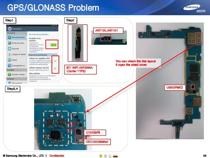
U102(GPS IC)
GPS/GLONASS Problem
Step1
Step3,4
L101
OSC100(26Mhz)
U500(PMIC)
You can check the this layout
if open the
U102(GPS IC)
GPS/GLONASS Problem
Step1
Step3,4
L101
OSC100(26Mhz)
U500(PMIC)
You can check the this layout
if open the
 Федеральный закон «Об основах охраны здоровья граждан в РФ»
 Ремесло культуры Луншань
 Праздник всех влюблённых
 The Hundred Years war Столетняя война
  «Букет роз» (материал-пластилин) Урок художественного труда 3 класс
 Бізнес-план кафе "White&black"
 Schüleraustausch, internationale Jugendprojekte
 Общие сведения о языке программирования Паскаль
 The Geographical Position of Ukraine
 Сертификация сыра
 Китайская Народная Республика –страна контрастов
 применение вывозных таможенных пошлин на нефть и нефтепродукты Мещерякова Юлия Т095
  Формирование функции голосообразования у младших школьников в условиях школы второго вида Важенина Анна Александровна, учитель-
 Анализ данных
  Презентация "Система учета энергоресурсов, как основной инструмент энергетического менеджмента" - скачать презентации по Эк
 Аттестация сотрудников компании, осень 2018: итоги. Аттестация, весна 2019: планы
 Шасси и каркасы
 Анализ логистических рисков в цепи поставок
  Шалаши, плоды и небо
 Получение вакуума
 Система отдыха в Турции
 Эстетика постимпрессионизма Урок МХК в 11 кл. Учитель: Е.А. Федюшина
 Микроволновой метод измерения удельного сопротивления полупроводниковых материалов
 Тайнопись работодателя Как «расшифровать» вакансию до собеседования? Ананьева Елизавета, редактор Rabota.ru Москва, 2011
  Презентация Особенности регулирования труда лиц, работающих в районах Крайнего Севера и приравненных к ним местностях
  Праздник Масленица
 Лекарственные средства, влияющие на афферентную иннервацию
  Строительство здания с ограждающей конструкцией из энергоэффективных мелкоштучных блоков