- Tests

Содержание
- 2. 2. In case of zone controller primary and secondary channel failure, what temperatures are maintained by
- 3. 3. During normal flight the avionics ventilation system controls the temperature of the cooling air by:
- 4. 4. Pack controllers, primary channel failure: The secondary channel takes over Pack is lost The secondary
- 5. 5. Pack controllers, secondary channel failure: Pack is lost No effect No effect on pack regulation.
- 6. 6. Pack controllers, primary and secondary channel failure: The pack is closed Pack outlet temperature is
- 7. 7. Hot air pressure regulating valve failed open: The temperature stays at the value selected when
- 8. 8. With bleed air supplied from the APU (APU bleed valve open) the pack flow is
- 9. 9. Each trim air valve optimizes the temperature by: Adding fresh air Modulation of pack flow
- 10. 10. The hot-air pressure regulating valves: Is spring-loaded open in the absence of air Opens automatically
- 11. 11. The pack flow control valve is: Electrically-operated and pneumatically-controlled Opens automatically during engine starting Pneumatically-operated
- 12. 12. The temperature selectors are located in: The cabin Both The cockpit
- 13. 13. Pack flow may be selected from: The cabin Both The cockpit
- 14. 14. When the cooling demand can’t be satisfied: In any case, flight idle is sufficient The
- 15. 15. What is the maximum normal cabin alt? 9,550 ft + 350 ft 14,000 ft 8,000
- 16. 16. Trim air valves are controlled by: The anti-ice valve The hot air pressure regulating valve
- 17. 17. The mixer unit is connected to: Packs, emergency ram air inlet and LP ground connector
- 18. 18. When the RAM AIR pushbutton is ON, the ram air valve will open: Provided DITCHING
- 19. b Packs are fixed at 15°C c Secondary channel operates as backup a Cabin zone temp
- 20. 20. Conditioned air is distributed to: Cockpit, cargo bays and cabin Cockpit, avionics bay and cabin
- 21. 21. The cabin zone temperature sensors are ventilated by the air extracted by the lavatory and
- 22. 22. Temperature regulation is automatic and is controlled by: Two pack controllers A zone controller All
- 23. 23. In case of pack controller failure, (primary and secondary channel) the pack outlet air temperature
- 24. 24. When the pack flow control knob is positioned to HI, air flow is: 150 %
- 25. 25. When using Engines bleed to supply the packs with the pack flow pushbutton to off,
- 26. 26. The pack flow control valve closes automatically in case of: Bleed valve failure, pack outlet
- 27. 27. In case of total zone controller failure: Hot air and trim air valves close and
- 28. 28. When the ditching switch is selected on, it sends a closure signal to: Ram air
- 29. 29. In flight, with press controller 1 in use, if it fails: You have to select
- 30. 30. In normal operation, pressurization is: Manually controlled All of the above Fully automatic
- 31. 31. The outflow valve is powered by: Three mechanically linked electric motors One of two electric
- 32. 32. During ground function operation, the outflow valve is: Fully close Positioned according to FMGS demands
- 33. 33. To see the position of the outflow valve it is necessary to call ECAM: Bleed
- 34. 34. Two identical, independent, automatic digital pressurization controllers are used for system control: Both controllers monitored
- 35. 35. The purpose of the safety valves is to avoid: Excessive negative differential Excessive positive pressure
- 36. 36. The safety valves are operated: Hydraulically Electronically Pneumatically
- 37. 37. When landing elevation is set to AUTO, the landing elevation is sent to the controller
- 38. 38. When cabin press mode selector is set to manual, the outflow valve is controlled by
- 39. 39. On ECAM cabin press page, the outflow valve indicator changes to amber if: Fully open
- 40. 40. On ECAM cabin press page, the safety valve indication changes to amber if: Both safety
- 41. 41. On ECAM cabin press page the cabin altitude indication changes to red when cabin altitude
- 42. 42. Following a sys 1 fault: System 2 must be selected by the crew Master caution
- 43. 43. Cabin pressurization starts at: Engine start Lift off Take-off power selection
- 44. 44. The pressure safety valves open at: 9.0 psi 7.6 psi 8.06 psi 8.6 psi
- 45. THE END=)
- 62. Скачать презентацию
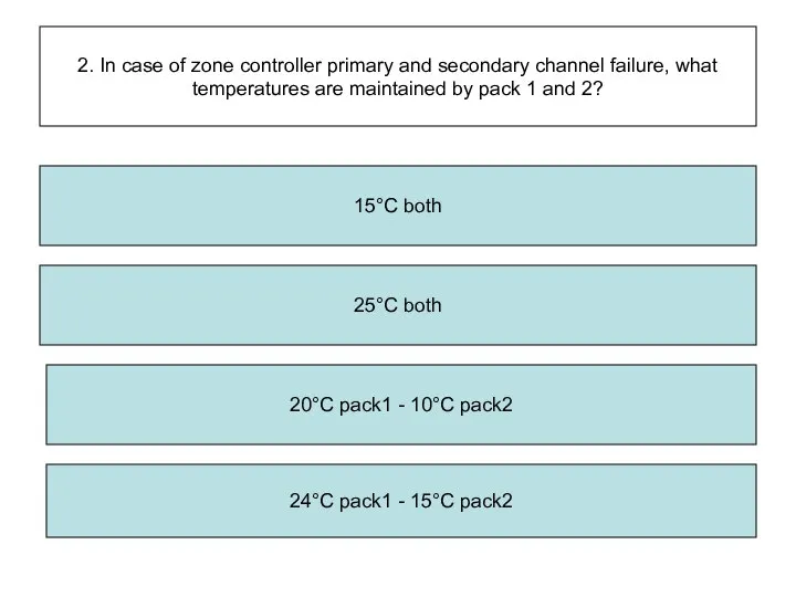
2. In case of zone controller primary and secondary channel failure,
2. In case of zone controller primary and secondary channel failure,
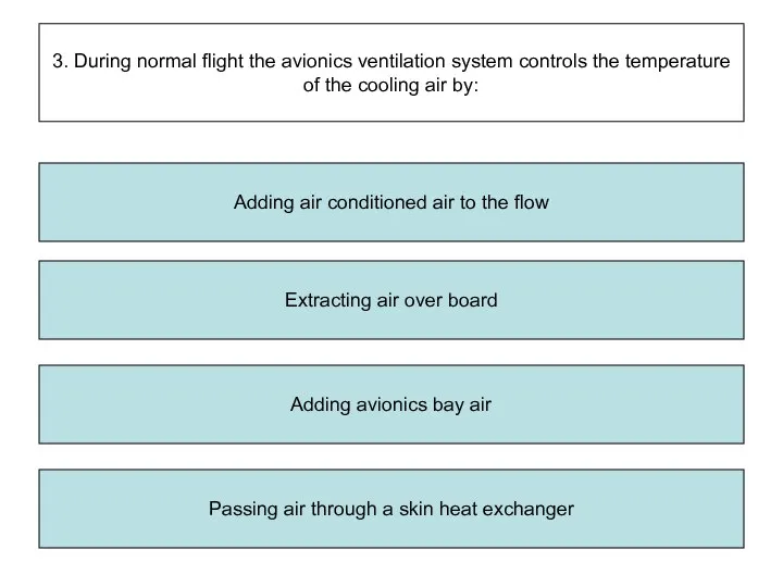
3. During normal flight the avionics ventilation system controls the temperature
3. During normal flight the avionics ventilation system controls the temperature
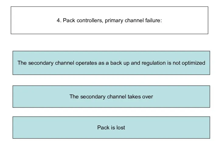
4. Pack controllers, primary channel failure:
The secondary channel takes over
Pack is
4. Pack controllers, primary channel failure:
The secondary channel takes over
Pack is
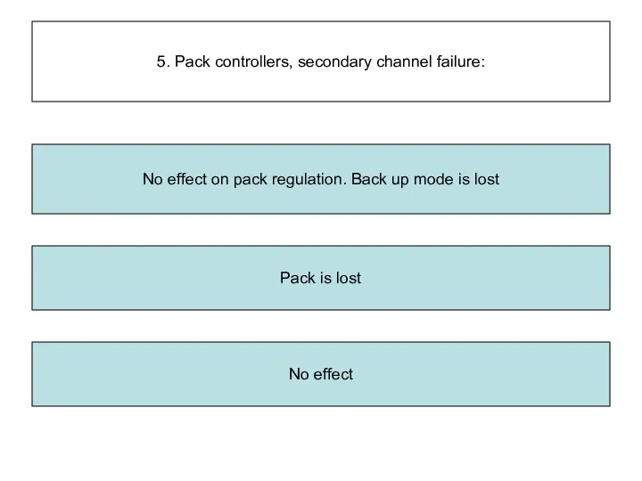
5. Pack controllers, secondary channel failure:
Pack is lost
No effect
No effect on
5. Pack controllers, secondary channel failure:
Pack is lost
No effect
No effect on
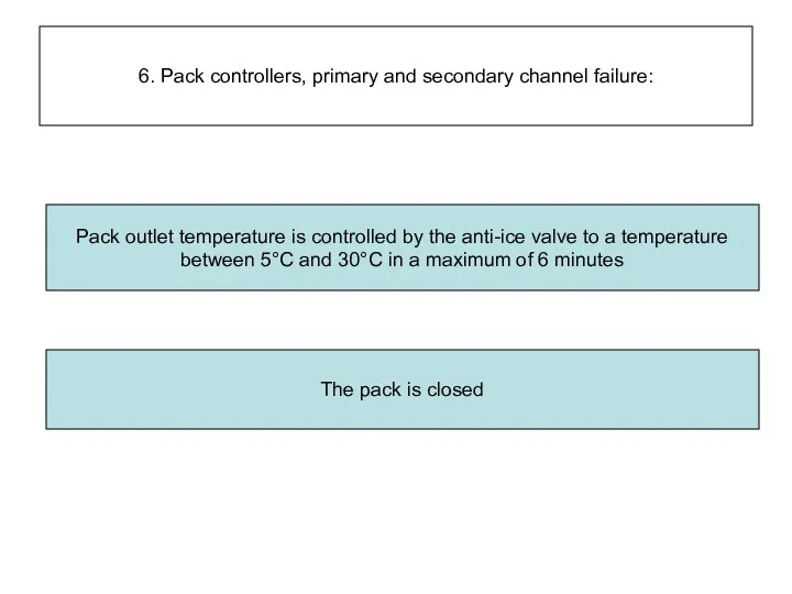
6. Pack controllers, primary and secondary channel failure:
The pack is closed
Pack
6. Pack controllers, primary and secondary channel failure:
The pack is closed
Pack
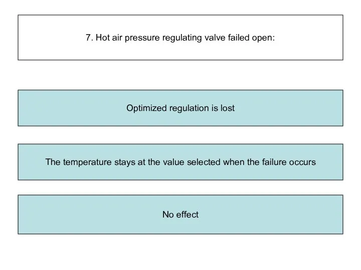
7. Hot air pressure regulating valve failed open:
The temperature stays at
7. Hot air pressure regulating valve failed open:
The temperature stays at
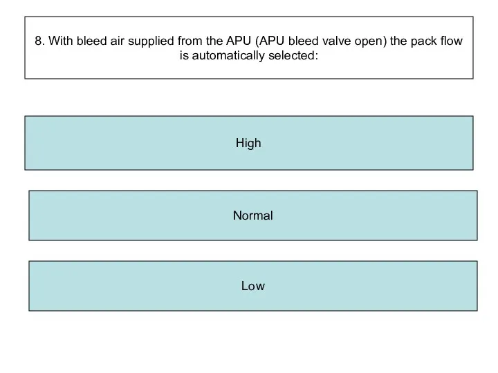
8. With bleed air supplied from the APU (APU bleed valve
8. With bleed air supplied from the APU (APU bleed valve
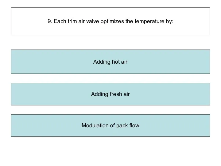
9. Each trim air valve optimizes the temperature by:
Adding fresh air
Modulation
9. Each trim air valve optimizes the temperature by:
Adding fresh air
Modulation
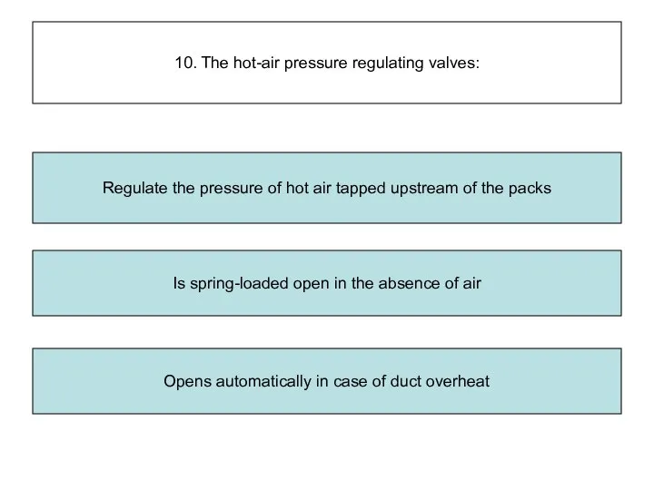
10. The hot-air pressure regulating valves:
Is spring-loaded open in the absence
10. The hot-air pressure regulating valves:
Is spring-loaded open in the absence
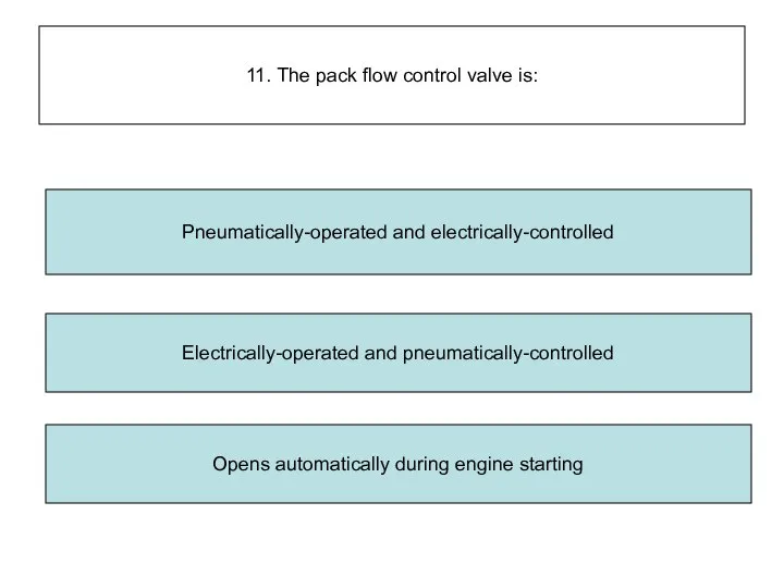
11. The pack flow control valve is:
Electrically-operated and pneumatically-controlled
Opens automatically during
11. The pack flow control valve is:
Electrically-operated and pneumatically-controlled
Opens automatically during
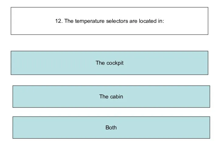
12. The temperature selectors are located in:
The cabin
Both
The cockpit
12. The temperature selectors are located in:
The cabin
Both
The cockpit
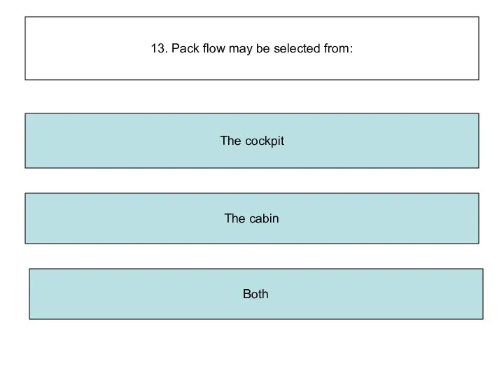
13. Pack flow may be selected from:
The cabin
Both
The cockpit
13. Pack flow may be selected from:
The cabin
Both
The cockpit
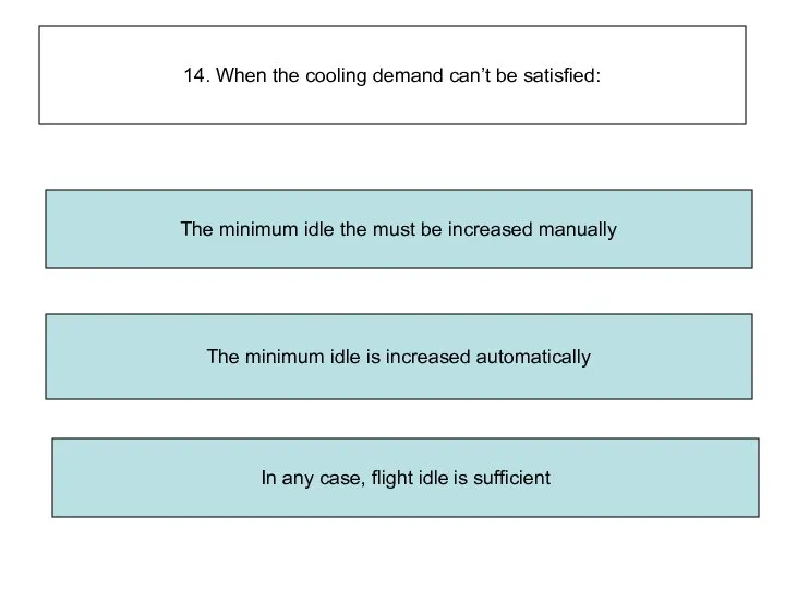
14. When the cooling demand can’t be satisfied:
In any case, flight
14. When the cooling demand can’t be satisfied:
In any case, flight
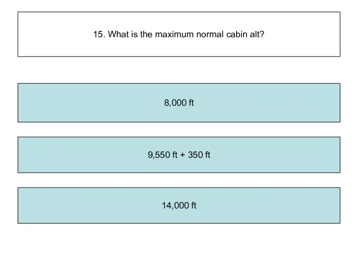
15. What is the maximum normal cabin alt?
9,550 ft + 350
15. What is the maximum normal cabin alt?
9,550 ft + 350
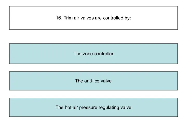
16. Trim air valves are controlled by:
The anti-ice valve
The hot air
16. Trim air valves are controlled by:
The anti-ice valve
The hot air
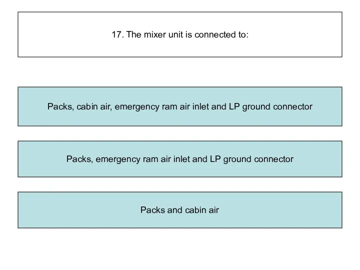
17. The mixer unit is connected to:
Packs, emergency ram air inlet
17. The mixer unit is connected to:
Packs, emergency ram air inlet
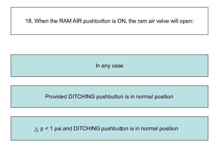
18. When the RAM AIR pushbutton is ON, the ram air
18. When the RAM AIR pushbutton is ON, the ram air
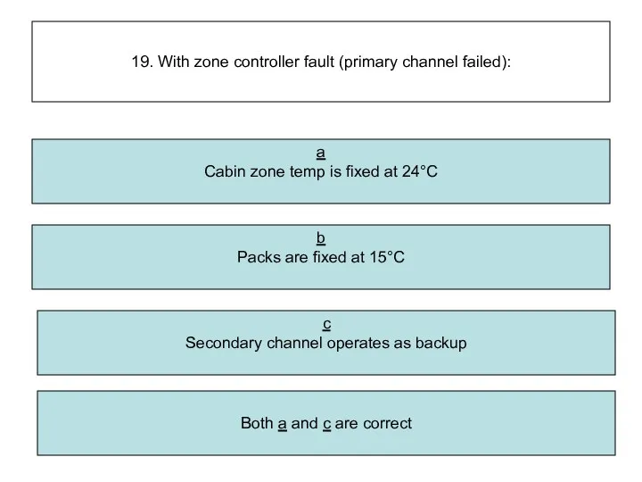
b
Packs are fixed at 15°C
c
Secondary channel operates as backup
a
Cabin zone temp
b
Packs are fixed at 15°C
c
Secondary channel operates as backup
a
Cabin zone temp
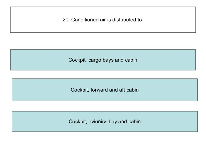
20. Conditioned air is distributed to:
Cockpit, cargo bays and cabin
Cockpit, avionics
20. Conditioned air is distributed to:
Cockpit, cargo bays and cabin
Cockpit, avionics
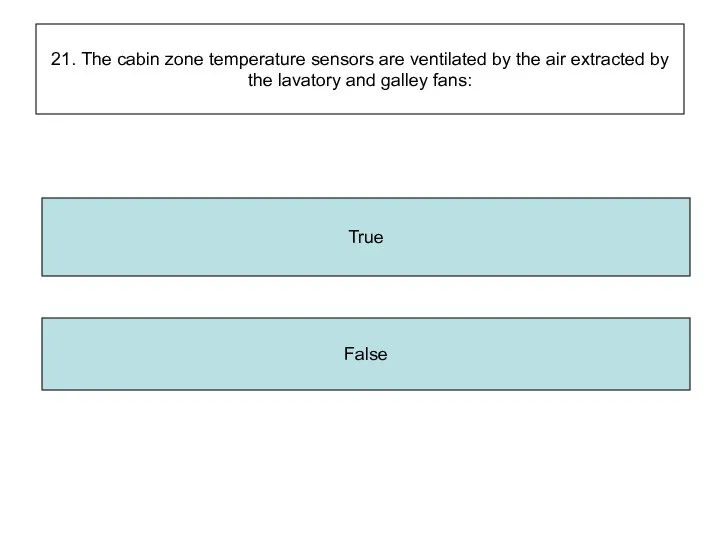
21. The cabin zone temperature sensors are ventilated by the air
21. The cabin zone temperature sensors are ventilated by the air
22. Temperature regulation is automatic and is controlled by:
Two pack controllers
A
22. Temperature regulation is automatic and is controlled by:
Two pack controllers
A
23. In case of pack controller failure, (primary and secondary channel)
23. In case of pack controller failure, (primary and secondary channel)
24. When the pack flow control knob is positioned to HI,
24. When the pack flow control knob is positioned to HI,
25. When using Engines bleed to supply the packs with the
25. When using Engines bleed to supply the packs with the
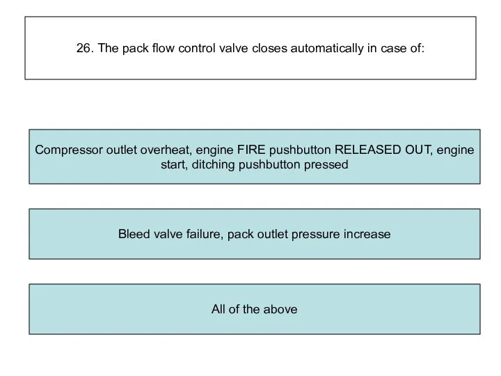
26. The pack flow control valve closes automatically in case of:
Bleed
26. The pack flow control valve closes automatically in case of:
Bleed
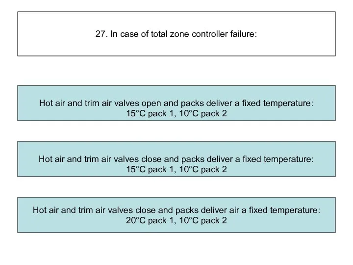
27. In case of total zone controller failure:
Hot air and trim
27. In case of total zone controller failure:
Hot air and trim
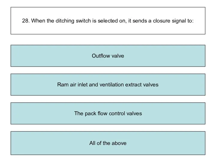
28. When the ditching switch is selected on, it sends a
28. When the ditching switch is selected on, it sends a
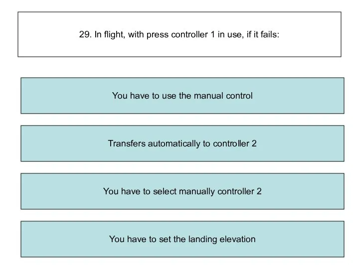
29. In flight, with press controller 1 in use, if it
29. In flight, with press controller 1 in use, if it
30. In normal operation, pressurization is:
Manually controlled
All of the above
Fully
30. In normal operation, pressurization is:
Manually controlled
All of the above
Fully
31. The outflow valve is powered by:
Three mechanically linked electric motors
31. The outflow valve is powered by:
Three mechanically linked electric motors
32. During ground function operation, the outflow valve is:
Fully close
Positioned
32. During ground function operation, the outflow valve is:
Fully close
Positioned
33. To see the position of the outflow valve it is
33. To see the position of the outflow valve it is
34. Two identical, independent, automatic digital pressurization controllers are used for
34. Two identical, independent, automatic digital pressurization controllers are used for
35. The purpose of the safety valves is to avoid:
Excessive negative
35. The purpose of the safety valves is to avoid:
Excessive negative
36. The safety valves are operated:
Hydraulically
Electronically
Pneumatically
36. The safety valves are operated:
Hydraulically
Electronically
Pneumatically
37. When landing elevation is set to AUTO, the landing elevation
37. When landing elevation is set to AUTO, the landing elevation
38. When cabin press mode selector is set to manual, the
38. When cabin press mode selector is set to manual, the
39. On ECAM cabin press page, the outflow valve indicator changes
39. On ECAM cabin press page, the outflow valve indicator changes
40. On ECAM cabin press page, the safety valve indication changes
40. On ECAM cabin press page, the safety valve indication changes
41. On ECAM cabin press page the cabin altitude indication changes
41. On ECAM cabin press page the cabin altitude indication changes
42. Following a sys 1 fault:
System 2 must be selected by
42. Following a sys 1 fault:
System 2 must be selected by
43. Cabin pressurization starts at:
Engine start
Lift off
Take-off power selection
43. Cabin pressurization starts at:
Engine start
Lift off
Take-off power selection
44. The pressure safety valves open at:
9.0 psi
7.6 psi
8.06 psi
8.6 psi
44. The pressure safety valves open at:
9.0 psi
7.6 psi
8.06 psi
8.6 psi
THE END=)
THE END=)


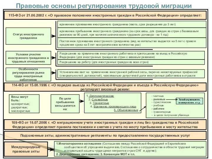 Презентация "Правовые основы регулирования трудовой миграции" - скачать презентации по Экономике
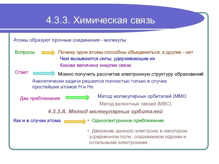 Химическая связь
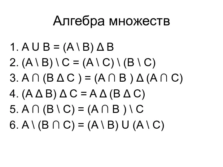 АЛГЕБРА МНОЖЕСТВ
  Гальванизация
  Retele de calculatoare
 Ц в е т о в е д е н и е Карточка 4
 Организация лечебной физической культуры в лечебно-профилактических учреждениях
 Научный эксперимент
 Гражданское право. Виды договоров
 ИНОСТРАННЫЕ ЯЗЫКИ НА НЕЯЗЫКОВЫХ ФАКУЛЬТЕТАХ ВУЗОВ
 Система команд МП х86
 Защита чести, достоинства и деловой репутации
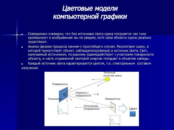 Цветовые модели компьютерной графики
 Дорога японского самурая (рыцаря)
 Великие путешественники. Витус Беринг - презентация для начальной школы
 Разработка проекта системы наземного телевизионного вещания
  Звёзды и созвездия Урок 22 2 класс
 Как смотреть живопись
 Щукина Оксана Павловна Учитель английского языка МОУ ЧСШ №1 Разработать презентацию по дисциплине (теме курса)
 Презентация на тему: Путешествие в Санкт-Петербург
 Макияж тигра - презентация для начальной школы_
 Концепция аналитического сигнал в радиотехнике
 Stéréotypes sur la France
 Вказівники та посилання. Динамічні масиви
 Региональный учебный центр бизнес-навыков в г. Мариуполь. Проект реализуется при поддержке ПРООН и правительства Японии
 МАЛОБЮДЖЕТНЫЙ МАРКЕТИНГ семинар Агарков Антон Александрович
 Кафедра нормальной физиологии КрасГМА Общая физиология ЦНС
  Молитва