- Viera Plasma Display. PC Board Recycling. Component Level Repair

Содержание
- 2. Curriculum Content Course 1 PCI PCB Recycling Program/Process Model line-up/PC board functionality Course 2 PCB Recycling
- 3. Servicentre determines a returnable PC board is defective. Servicecentre orders replacement PC board from Panasonic National
- 4. Returnable Parts Return Form: Must be completely filled out and sent together with the defective PC
- 5. Model line up and PC board functionality
- 6. 2005/2006 PDP Line-up 2005 2006 TH-50PX500 TH-42PX500 TH-42PD50 TH-50PX50 TH-42PX50 TH-37PX50 TH-50PX600 TH-42PX600 TH-42PD60 TH-50PX60 TH-42PX60
- 7. 2005: 50PX500/PX50 2006: 50PX600/PX60 Differences 1. The PB and Z board are now on the PA
- 8. 2005 & 2006 PC Board Difference (for 42 & 37” models): 2005: 42/37/PX500/PX50/PD50 2006: 42/37/PX600/PX60/PD60 Differences
- 9. 2005 Plasma TV PC Board List
- 10. 2006 Plasma TV PC Board List
- 11. 2005 & 2006 PC Board Difference: Easier connection and parts change Lead connector Bridge connector Before
- 12. General Signal Circuit Flow for 2006 Model (42V & 37”): Input Source Signal Processor Panel Drive
- 13. R,G,B :10Bit (MAIN) R,G,B :10Bit (Sub) SD Card DG OSD To D Board MAIN MICRO PROCESSOR
- 15. Скачать презентацию
Curriculum Content
Course 1
PCI PCB Recycling Program/Process
Model line-up/PC board functionality
Course 2
PCB Recycling
Curriculum Content
Course 1
PCI PCB Recycling Program/Process
Model line-up/PC board functionality
Course 2
PCB Recycling
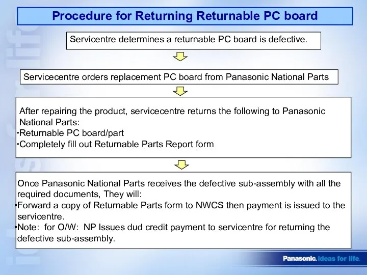
Servicentre determines a returnable PC board is defective.
Servicecentre orders replacement PC
Servicentre determines a returnable PC board is defective.
Servicecentre orders replacement PC
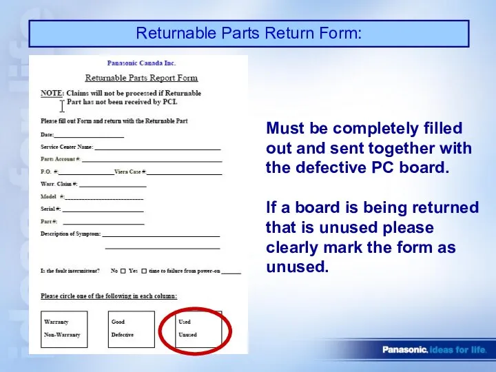
Returnable Parts Return Form:
Must be completely filled
out and sent together with
the
Returnable Parts Return Form:
Must be completely filled
out and sent together with
the
Model line up and PC board functionality
Model line up and PC board functionality
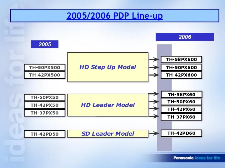
2005/2006 PDP Line-up
2005
2006
TH-50PX500
TH-42PX500
TH-42PD50
TH-50PX50
TH-42PX50
TH-37PX50
TH-50PX600
TH-42PX600
TH-42PD60
TH-50PX60
TH-42PX60
TH-37PX60
SD Leader Model
HD Step Up Model
HD Leader Model
TH-58PX600
TH-58PX60
2005/2006 PDP Line-up
2005
2006
TH-50PX500
TH-42PX500
TH-42PD50
TH-50PX50
TH-42PX50
TH-37PX50
TH-50PX600
TH-42PX600
TH-42PD60
TH-50PX60
TH-42PX60
TH-37PX60
SD Leader Model
HD Step Up Model
HD Leader Model
TH-58PX600
TH-58PX60
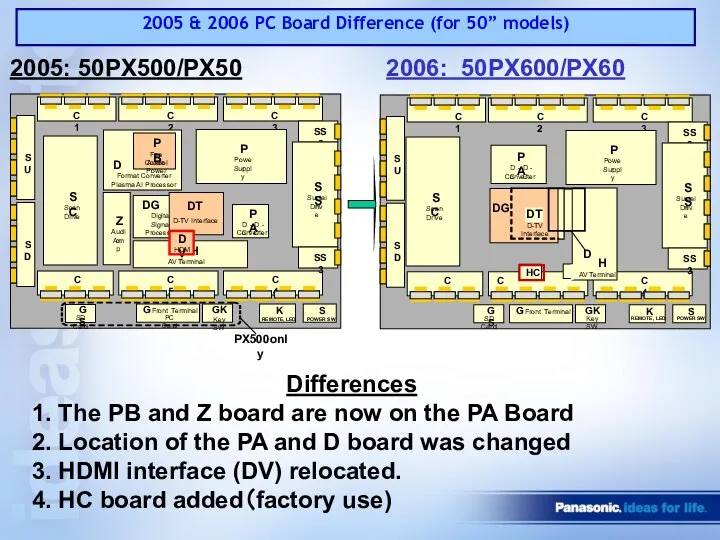
2005: 50PX500/PX50
2006: 50PX600/PX60
Differences
1. The PB and Z board are now
2005: 50PX500/PX50
2006: 50PX600/PX60
Differences
1. The PB and Z board are now
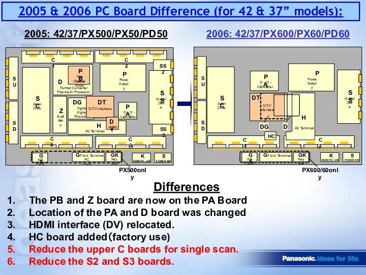
2005 & 2006 PC Board Difference (for 42 & 37” models):
2005:
2005 & 2006 PC Board Difference (for 42 & 37” models):
2005:
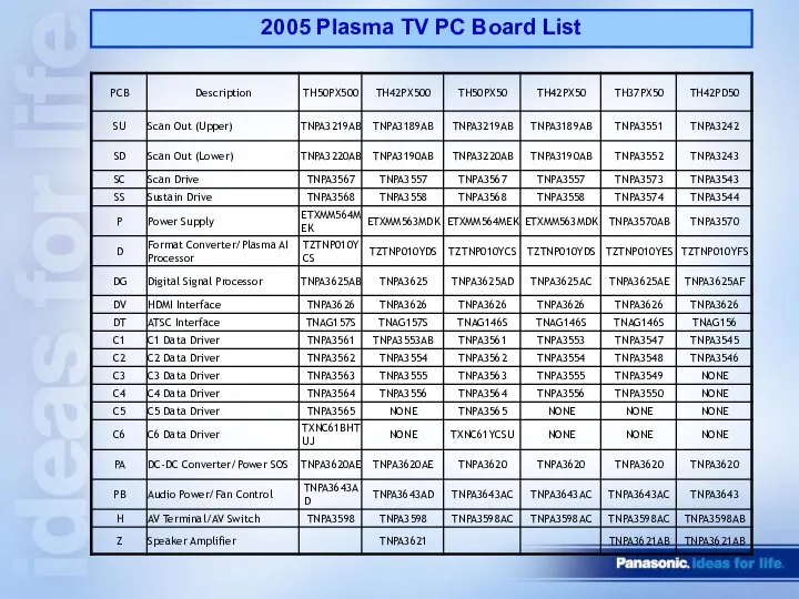
2005 Plasma TV PC Board List
2005 Plasma TV PC Board List
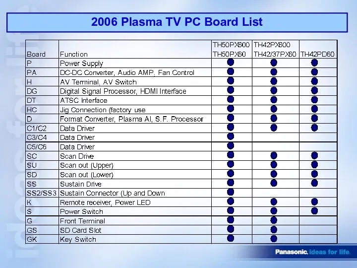
2006 Plasma TV PC Board List
2006 Plasma TV PC Board List
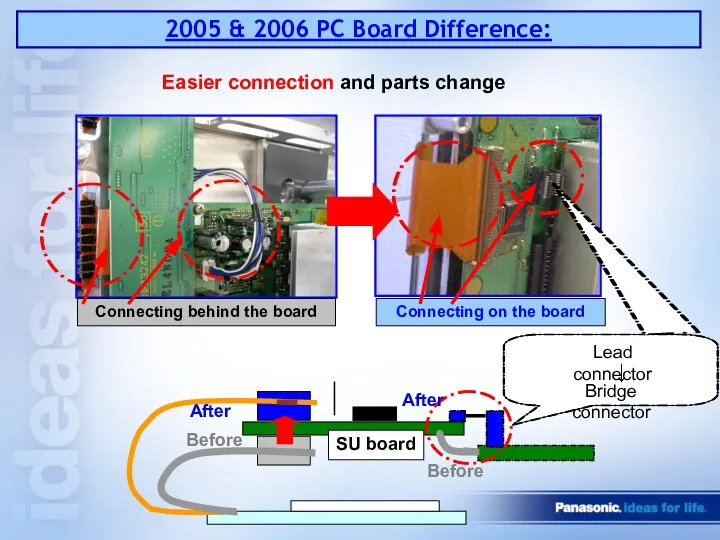
2005 & 2006 PC Board Difference:
Easier connection and parts change
Lead connector
Bridge
2005 & 2006 PC Board Difference:
Easier connection and parts change
Lead connector
Bridge
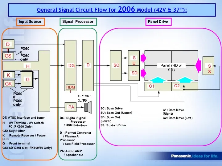
General Signal Circuit Flow for 2006 Model (42V & 37”):
Input Source
Signal
General Signal Circuit Flow for 2006 Model (42V & 37”):
Input Source
Signal
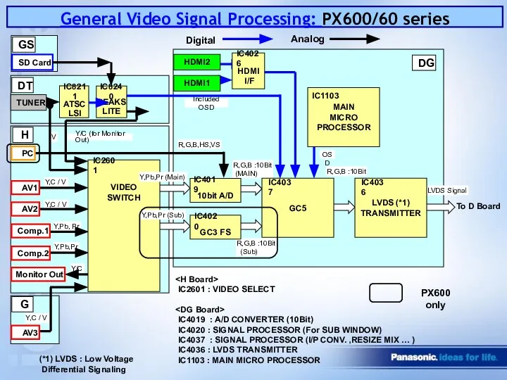
R,G,B :10Bit
(MAIN)
R,G,B :10Bit
(Sub)
SD Card
DG
OSD
To D Board
MAIN
MICRO PROCESSOR
IC1103
IC2601
H
10bit A/D
GC3 FS
GC5
IC4037
HDMI2
(*1)
R,G,B :10Bit
(MAIN)
R,G,B :10Bit
(Sub)
SD Card
DG
OSD
To D Board
MAIN
MICRO PROCESSOR
IC1103
IC2601
H
10bit A/D
GC3 FS
GC5
IC4037
HDMI2
(*1)
 Строительные технологии. Выбор и привязка грузоподъемной машины
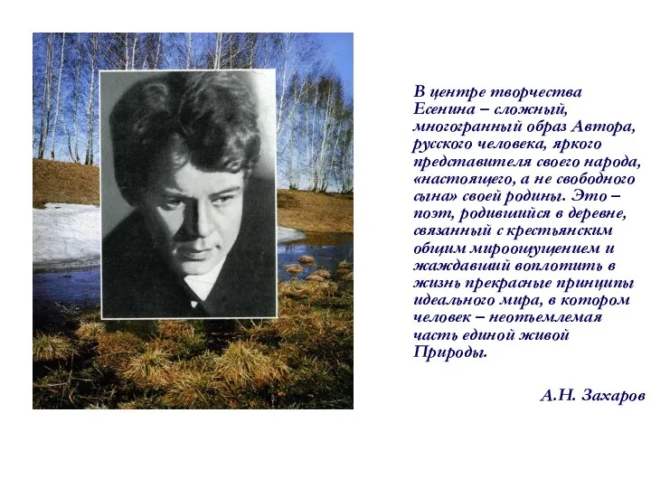 Сергей Александрович Есенин (1895-1925)
 Классификация ассортимента и показателей качества бытовых холодильников
 Інформаційна система дослідників керованості поширенням розрядів і імпульсів в неоднорідному електричному полі, зарядженому газ
 Путешествие в космос
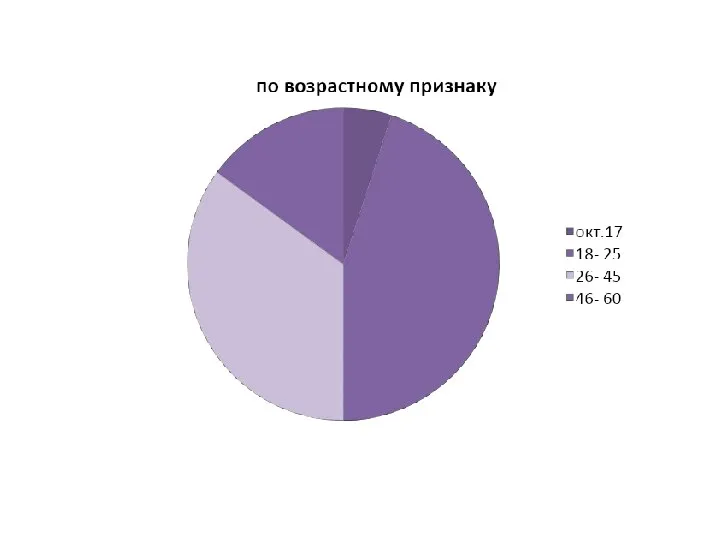 сегментирование диаграммы
 Считалочка «Муркин счет»
 Кодирование информации
  История Олимпийских игр
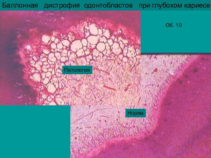 2 занятие_стом.ppt
 Презентация на тему "НЕНАРКОТИЧЕСКИЕ АНАЛЬГЕТИКИ" - скачать презентации по Медицине
 Назначение и возможности языка PHP. Переменные, константы и типы данных РНР. Лекция №1
 Понятие и виды форм права
  Образование. Приоритетность образования
 immunnaya_sistema
 Kidris.ru - сервис анонимных сообщений
 Последовательностные схемы или схемы без элементов памяти
 Организация основного производства на предприятиях сервиса
 Клинопись
 Автомобильные дороги и городские улицы 7
 Язык С. Базовые конструкции и операторы
 Этиология, эпидемиология туберкулёза
  СЕРТИФИКАЦИЯ КОФЕ И КОФЕЙНЫХ НАПИТКОВ
 Классификация видов испытаний конструкций зданий и сооружений
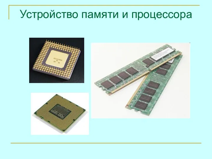 Устройство памяти и процессора. Память ЭВМ
 «Ученик, который учится без желания, это птица без крыльев». Саади
 Научно-инновационная система Франции
  О патентной системе налогообложения