- TE transmissions training program

Содержание
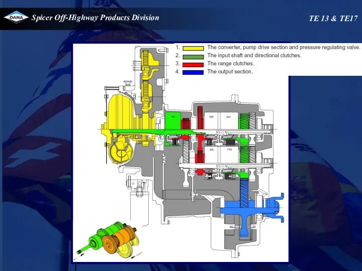
- 2. Basic connverter /transmission theory movie
- 3. TE transmissions Electronic controlled modulation Clutch overlap control Inching control
- 4. Electronic controlled modulation (E.C.M.) Controller
- 5. Modulated build up of pressure in the clutch Electronic controlled modulation (E.C.M.) Controller different modulation pressure
- 6. Modulated build up of pressure in the clutch Controller different modulation energy different modulation in power
- 7. Overlap control Controller
- 8. Electronic controlled inching Controller
- 9. TE13/17 transmission
- 10. TE 13 & TE17
- 11. 340 F T E 13 3 XX - XX Converter specific ¨dash number¨ Model Wheel Group
- 12. Converter/Transmission Oil System Capacity 16,5L Lines and cooler not included Oil Type ? Only ATF Dexron
- 13. Ratios Technical specifications TE 13 & TE17
- 14. Temperature specifications Normal operating temperature 70 - 120°C at temperature check port 71 converter out Maximum
- 15. At 2200 RPM 24 – 29 Bar Converter : 1.0 -4.0 l/m Each range clutch :
- 16. Safety valve cracking pressure 7,5 bar Converter out pressure (to cooler) 3.0 – 3.5 bar. at
- 17. Pump flow At 2200 RPM : 90 to 110 lpm TE 13 & TE17
- 18. Electrical specifications TE 13 & TE17
- 19. HYDRAULIC COOLER LINES SPECIFICATIONS. Minimum 19 mm internal diameter for lines and fittings. Suitable for operation
- 20. TE 13 & TE17
- 21. Additional signals Speed sensors Engine speed combined with oil temperature pick up located at pump gear
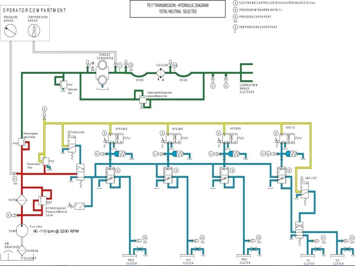
- 22. Wiring schematics TE 13 & TE17 Total neutral
- 23. Wiring schematics TE 13 & TE17
- 24. Control valve Variable force solenoids (VFS) VFS0 for forward VFS1 for 2nd VFS2 for reverse VFS3
- 25. Solenoid activation TE 13 & TE17
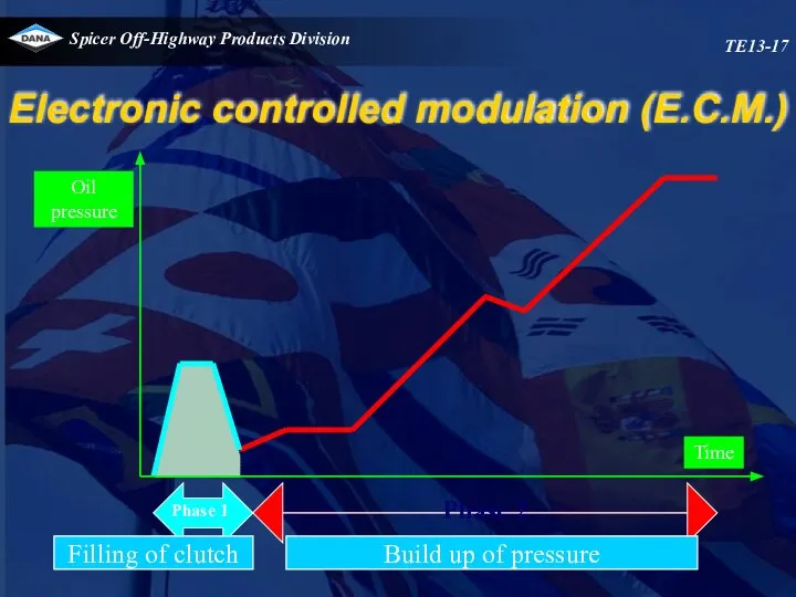
- 26. Electronic controlled modulation (E.C.M.) TE13-17
- 27. Operation of transmission TE 13 & TE17 The transmission is controlled by an APC200 box. This
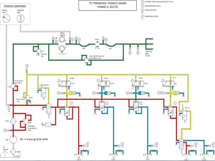
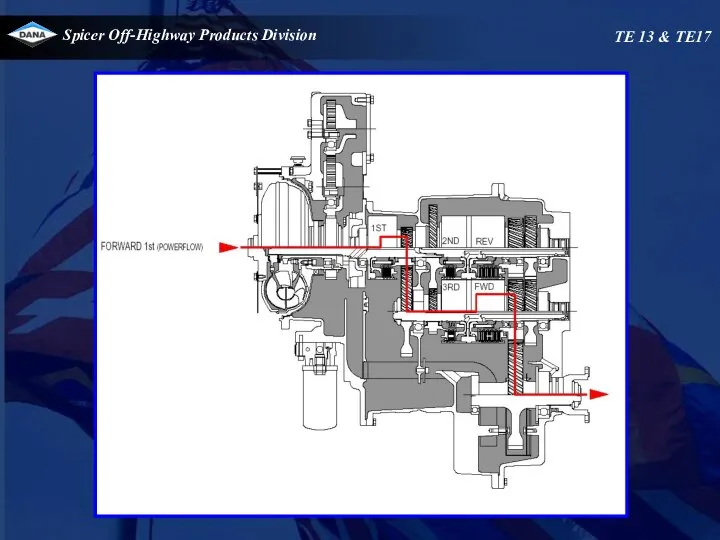
- 28. Operation of transmission TE 13 & TE17 Range selection When 1 st clutch is selected ,
- 29. Operation of transmission TE 13 & TE17 Total neutral selection Total neutral is only selected by
- 30. TE 13 & TE17 37 90 -110 lpm @ 2200 RPM
- 31. Neutral TE 13 & TE17
- 32. TE 13 & TE17 90 -110 lpm @ 2200 RPM 37
- 33. TE 13 & TE17
- 34. TE 13 & TE17 90 -110 lpm @ 2200 RPM 37
- 35. TE 13 & TE17
- 36. TE 13 & TE17 90 -110 lpm @ 2200 RPM 37
- 37. TE 13 & TE17
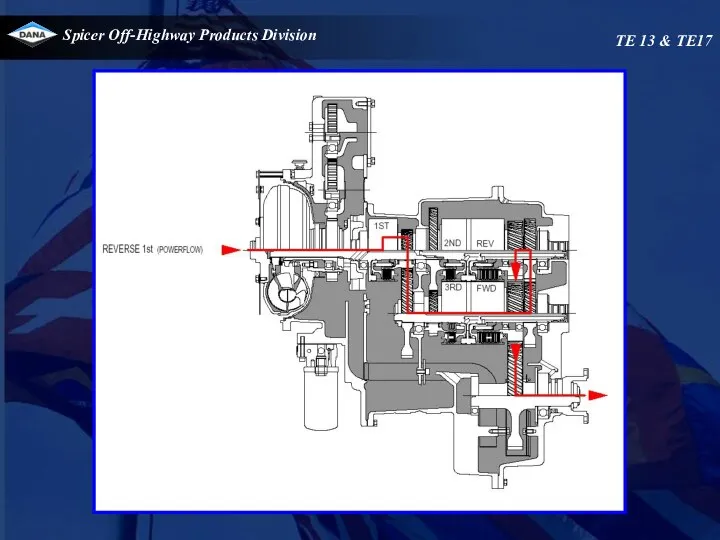
- 38. TE 13 & TE17 90 -110 lpm @ 2200 RPM 37
- 39. TE 13 & TE17
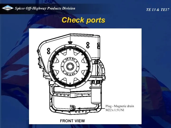
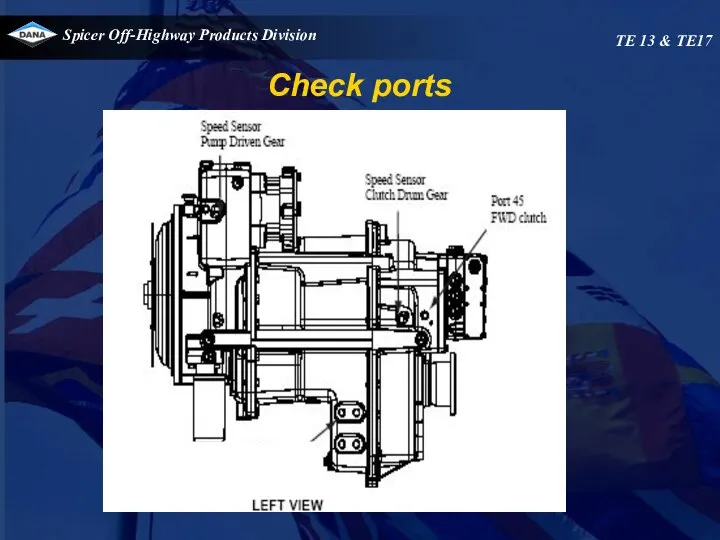
- 40. Check ports TE 13 & TE17
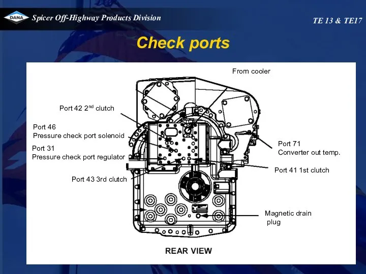
- 41. Check ports TE 13 & TE17 Port 42 2nd clutch Port 46 Pressure check port solenoid
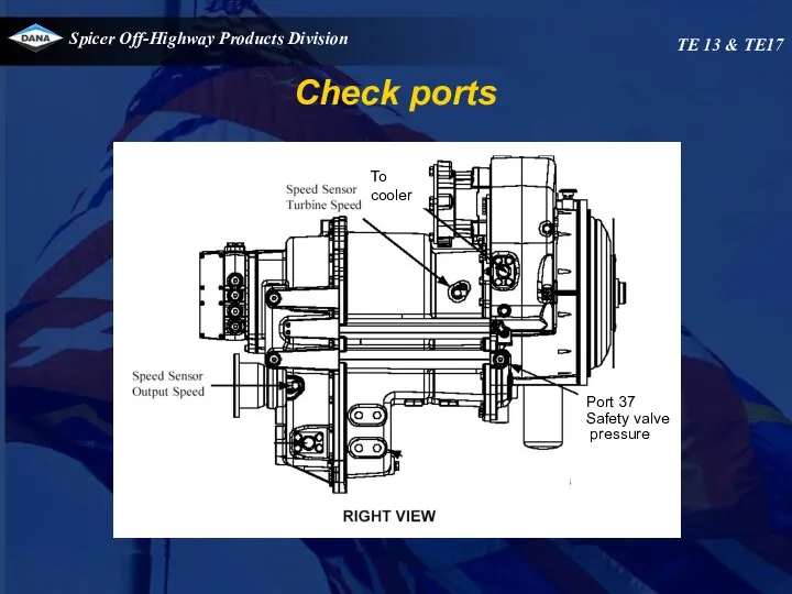
- 42. Check ports TE 13 & TE17 To cooler Port 37 Safety valve pressure Safaty valve mmmpressure
- 43. Check ports TE 13 & TE17 Safaty valve pressure Engine
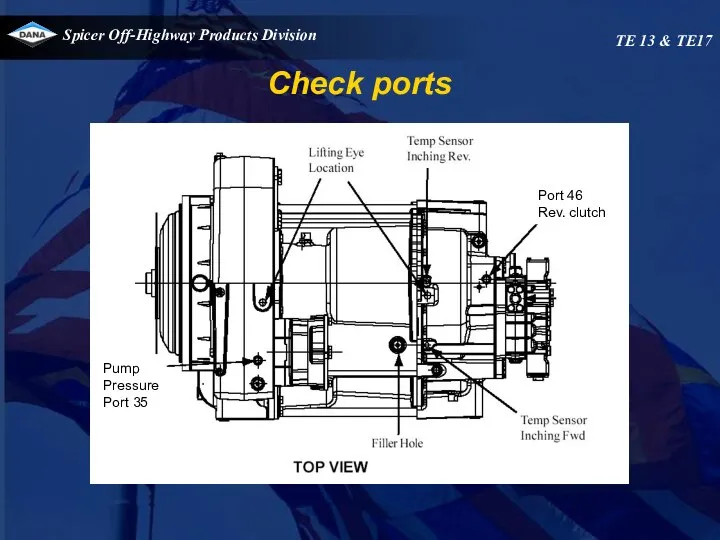
- 44. Check ports TE 13 & TE17 Port 46 Rev. clutch Rev. clutch Pump Pressure Port 35
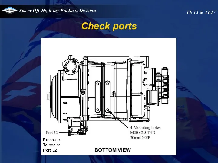
- 45. Check ports TE 13 & TE17 Pressure To cooler Port 32
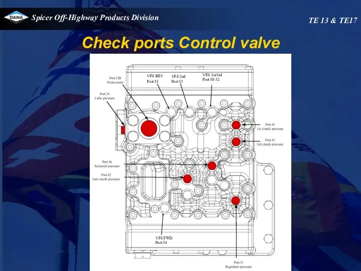
- 46. Check ports Control valve TE 13 & TE17 VFS REV Port 55 VFS 2nd Port 51
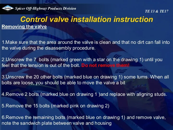
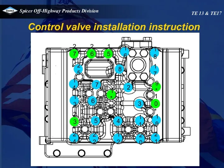
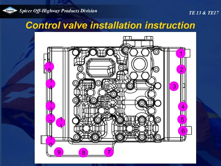
- 47. Control valve installation instruction Removing the valve 1.Make sure that the area around the valve is
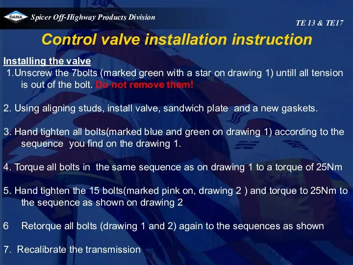
- 48. Control valve installation instruction Installing the valve 1.Unscrew the 7bolts (marked green with a star on
- 49. 27* 26* 15* 16 18 25 24 22 12 20 21 23* 5 4 11 19
- 50. Control valve installation instruction TE 13 & TE17 15 9 8 7 10 11 12 13
- 51. Speed sensor installation TE 13 & TE17 Combined engine speed sensor and temperature Turbine, drum and
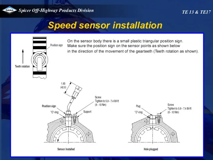
- 52. Speed sensor installation TE 13 & TE17
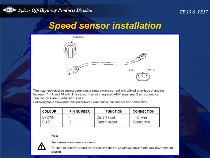
- 53. Speed sensor installation TE 13 & TE17
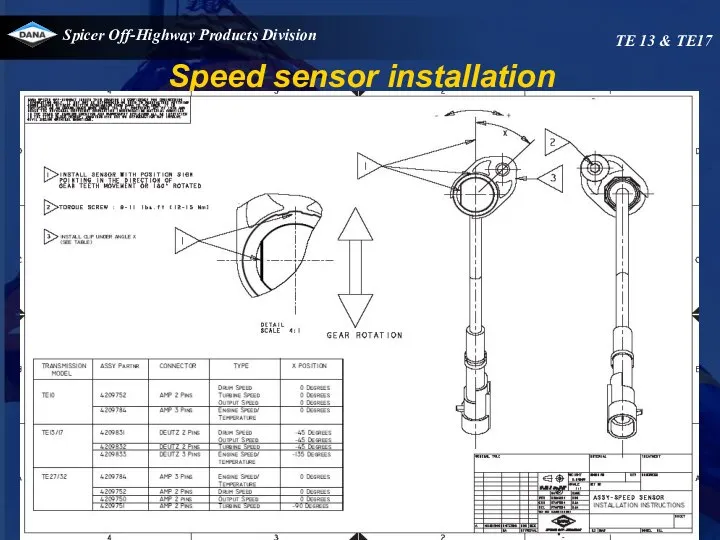
- 54. Speed sensor installation TE 13 & TE17
- 55. TE32 transmission
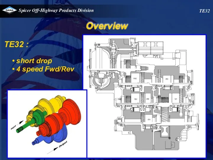
- 56. Overview TE32 TE32 : short drop 4 speed Fwd/Rev
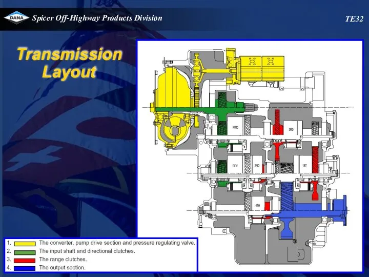
- 57. TE32 Transmission Layout
- 58. 1X.X T E 32 4 X X - XX Converter specific ¨dash number¨ Model Wheel Group
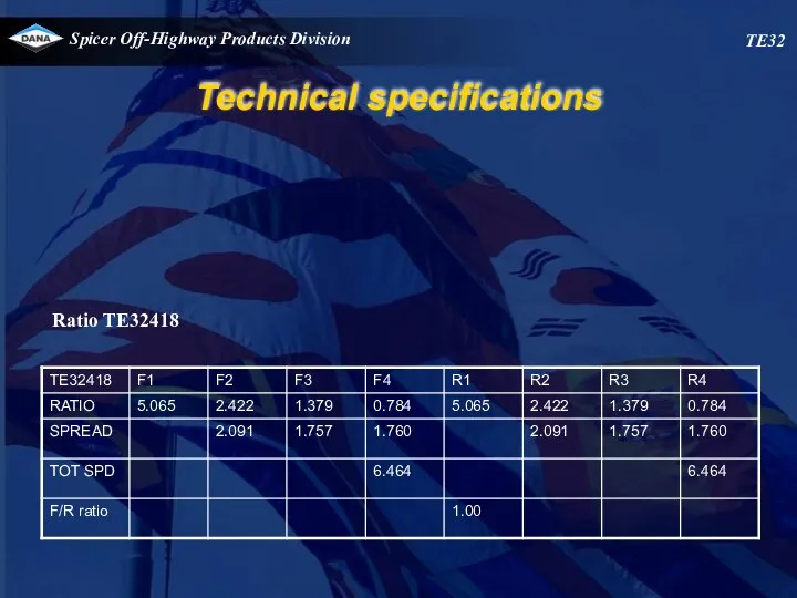
- 59. TE32 Technical specifications Ratio TE32418
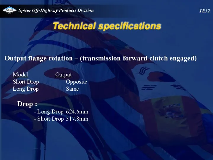
- 60. TE32 Technical specifications Output flange rotation – (transmission forward clutch engaged) Model Output Short Drop Opposite
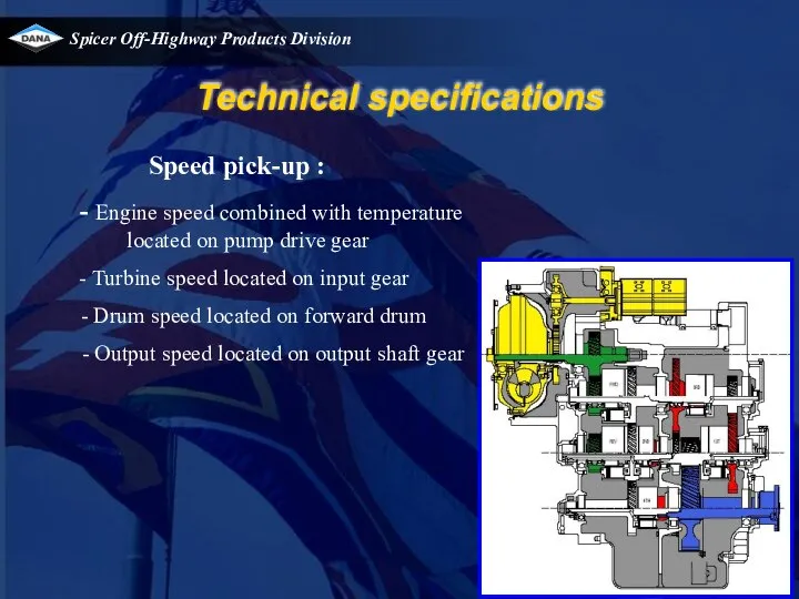
- 61. Speed pick-up : - Engine speed combined with temperature located on pump drive gear Turbine speed
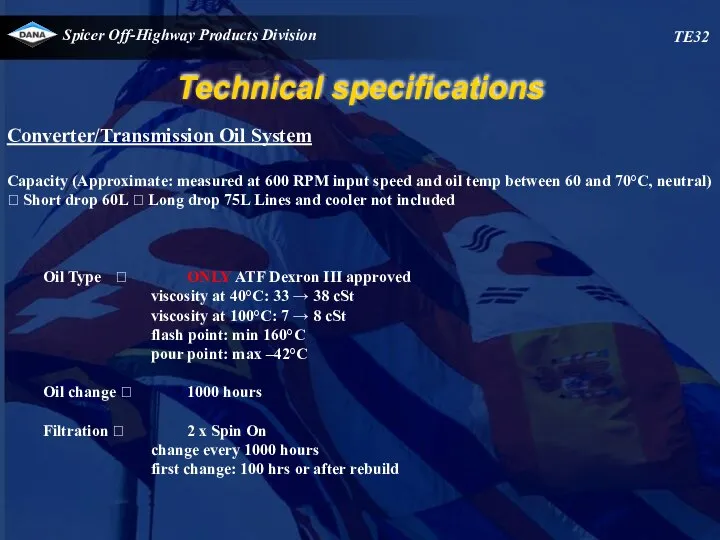
- 62. TE32 Technical specifications Converter/Transmission Oil System Capacity (Approximate: measured at 600 RPM input speed and oil
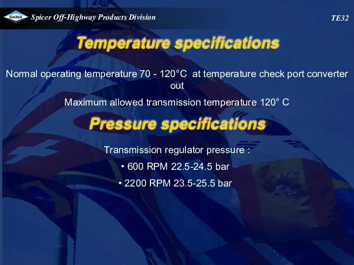
- 63. Normal operating temperature 70 - 120°C at temperature check port converter out Maximum allowed transmission temperature
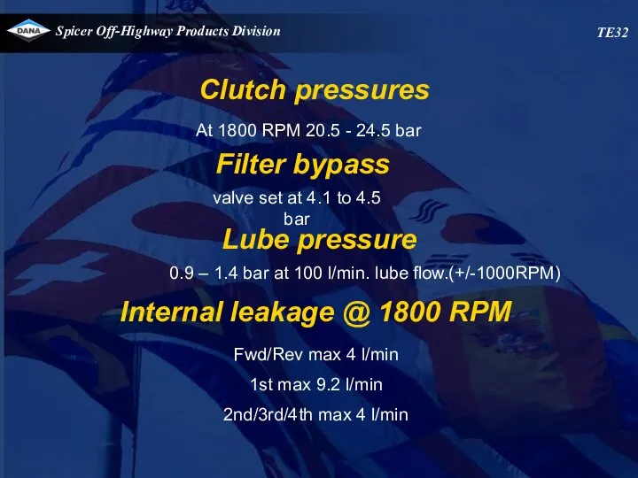
- 64. At 1800 RPM 20.5 - 24.5 bar Fwd/Rev max 4 l/min 1st max 9.2 l/min 2nd/3rd/4th
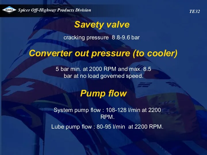
- 65. Savety valve cracking pressure 8.8-9.6 bar Converter out pressure (to cooler) 5 bar min. at 2000
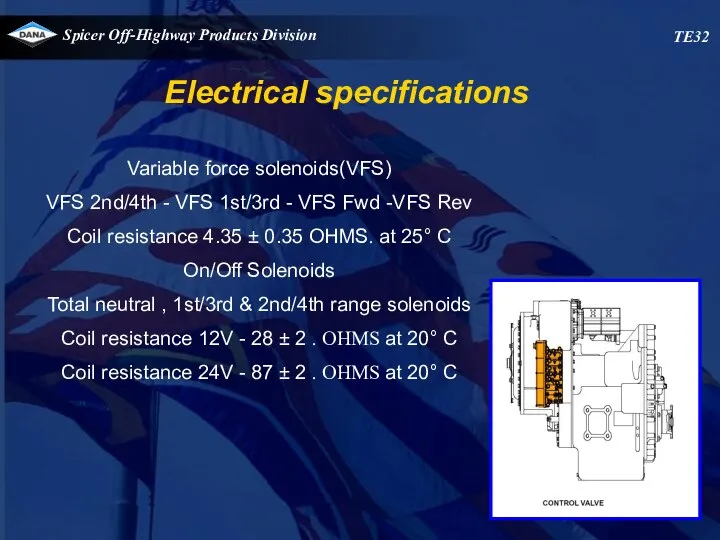
- 66. Variable force solenoids(VFS) VFS 2nd/4th - VFS 1st/3rd - VFS Fwd -VFS Rev Coil resistance 4.35
- 67. Speed sensors Type Magneto resistive sensor. Sensing distance up to 1.8 mm Sensor signal generates a
- 68. HYDRAULIC COOLER LINES SPECIFICATIONS. Minimum 32 mm internal diameter for lines and fittings. Suitable for operation
- 69. TE32
- 70. Additional signals Speed sensors Engine speed combined with oil temperature pick up located at pump gear
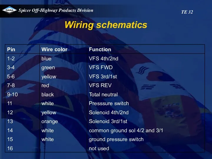
- 71. Wiring schematics TE 32
- 72. Wiring schematics TE 32
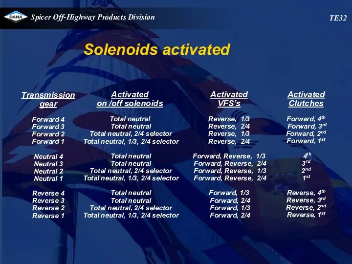
- 73. TE32 Solenoids activated Transmission gear Forward 4 Forward 3 Forward 2 Forward 1 Neutral 4 Neutral
- 74. Electronic controlled modulation (E.C.M.) TE27-32
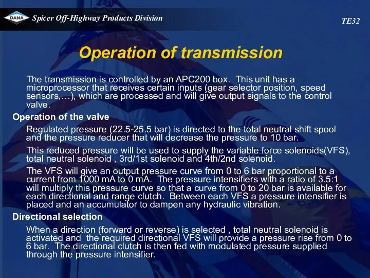
- 75. Operation of transmission TE32 The transmission is controlled by an APC200 box. This unit has a
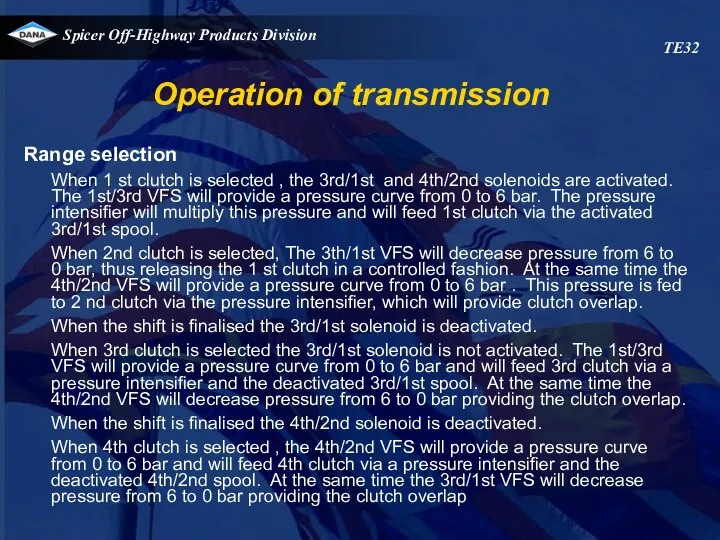
- 76. Operation of transmission TE32 Range selection When 1 st clutch is selected , the 3rd/1st and
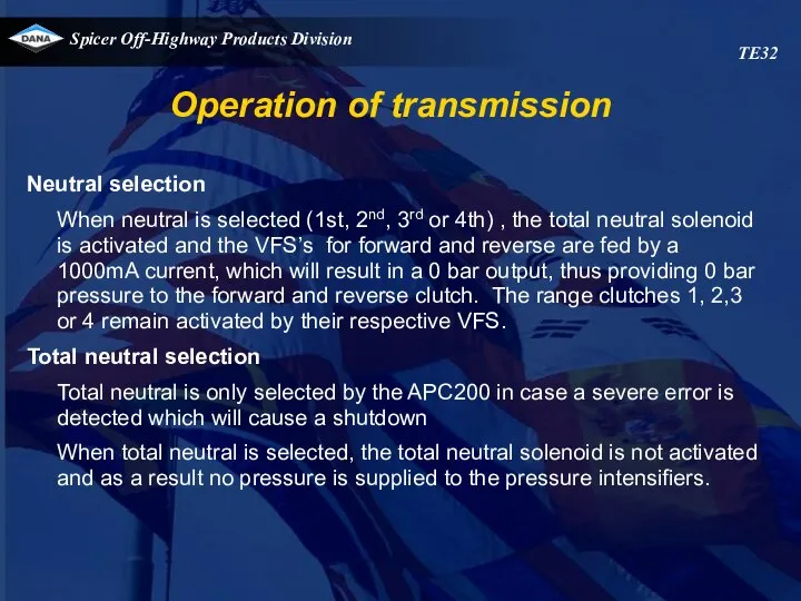
- 77. Operation of transmission TE32 Neutral selection When neutral is selected (1st, 2nd, 3rd or 4th) ,
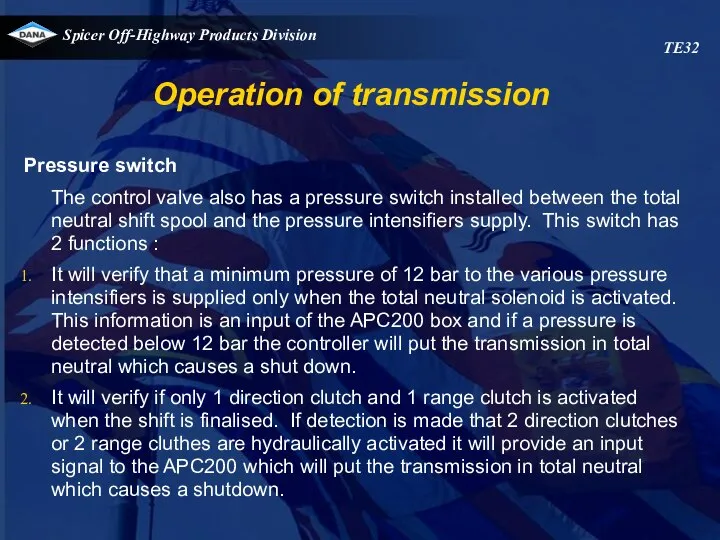
- 78. Operation of transmission TE32 Pressure switch The control valve also has a pressure switch installed between
- 79. TE32 VFS 1/3 VFS 2/4
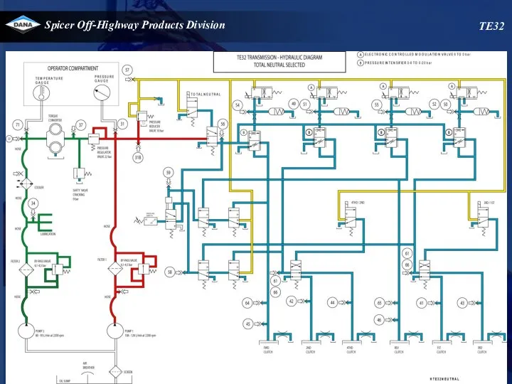
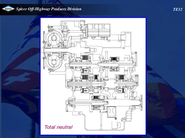
- 80. TE32 Total neutral
- 81. TE32 VFS 1/3 VFS 2/4
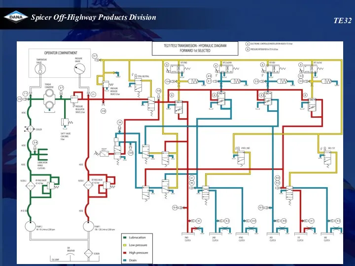
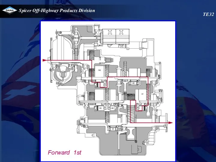
- 82. TE32 Forward 1st
- 83. TE32 VFS 1/3 VFS 2/4
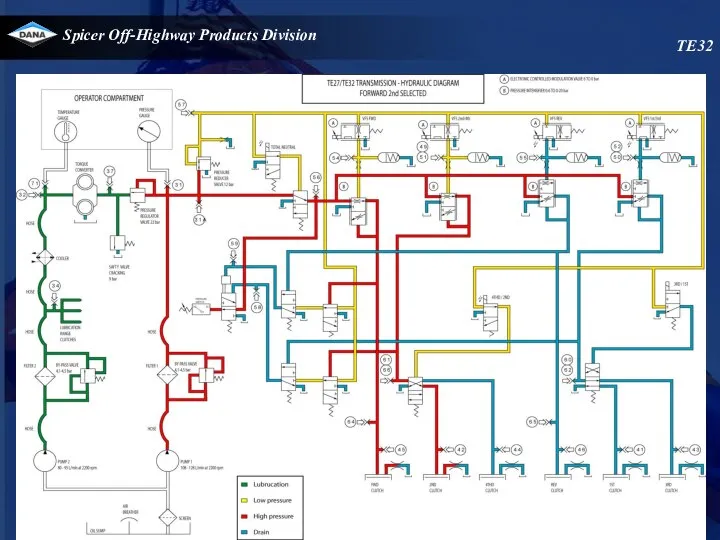
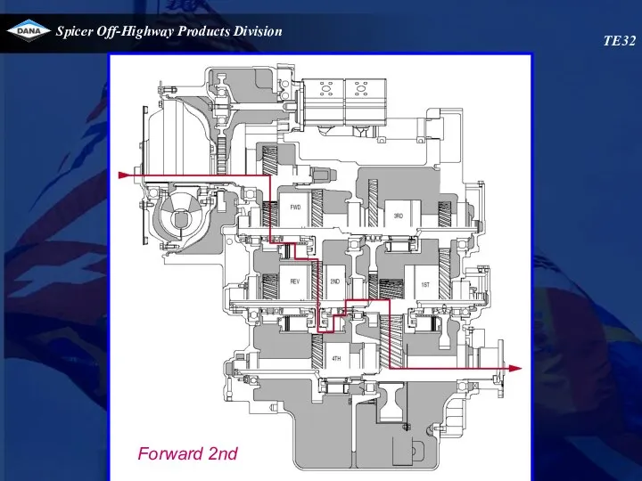
- 84. TE32 Forward 2nd
- 85. TE32 VFS 1/3 VFS 2/4
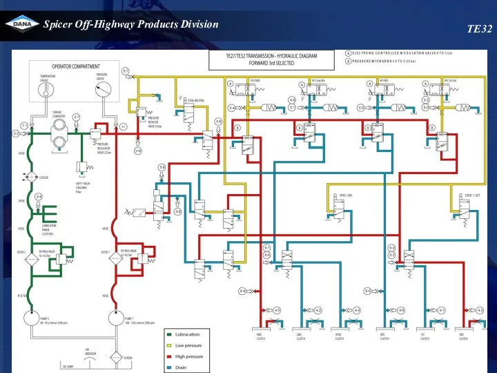
- 86. TE32 Forward 3rd
- 87. TE32 VFS 1/3 VFS 2/4
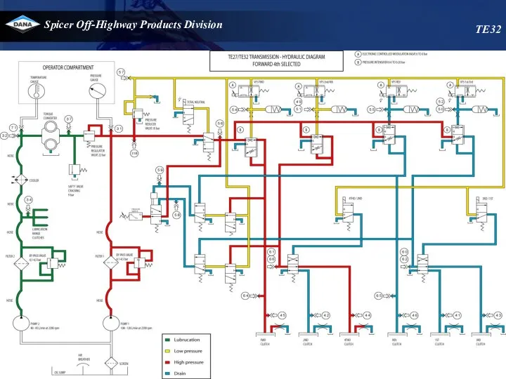
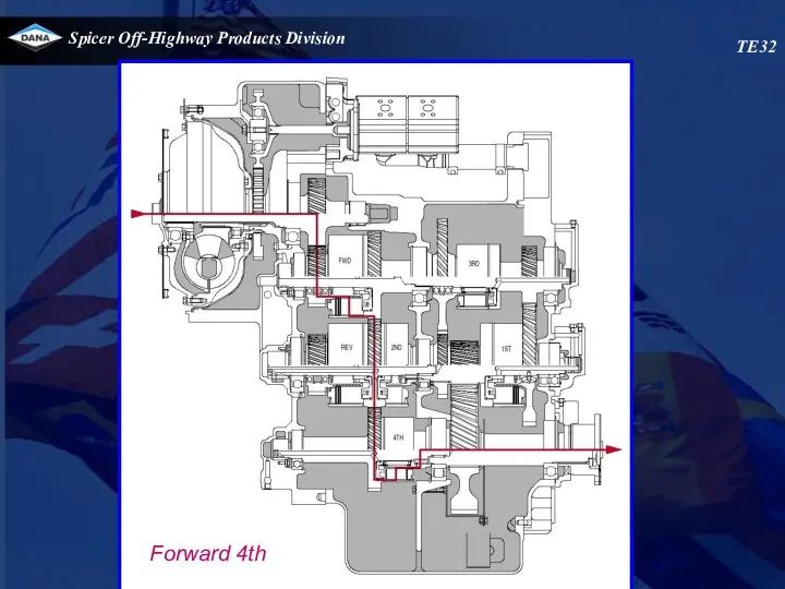
- 88. TE32 Forward 4th
- 89. TE32 VFS 1/3 VFS 2/4
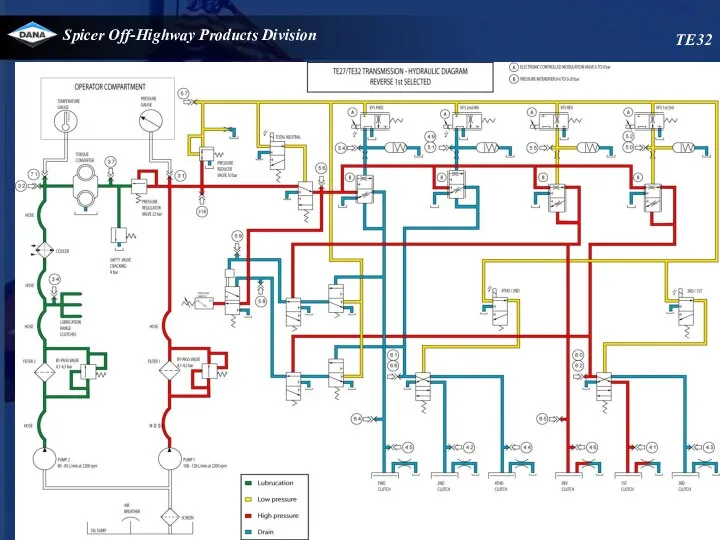
- 90. TE32 Reverse 1st
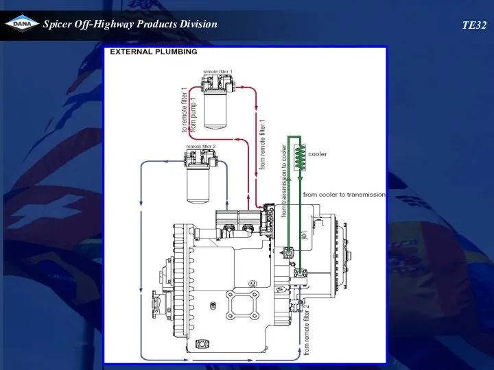
- 91. Connections - top view To remote filter from pump 2 To remote filter from pump 1
- 92. Pressure check 1st clutch port 41 Oil level check port 1/4 NPT Checkports - left view
- 93. Checkports - right view TE32 Reg. Pressure port 31 Converter In Pres port 37 To cooler
- 94. Checkports - front view TE32 2nd clutch port 42 Rev clutch port 46 4th clutch port
- 95. Checkports - rear view TE32 From filter 1 Conv out press port 32 Temp switch Converter
- 96. Speed sensor location TE32 Engine speed & transmission temperature sensor Drum speed sensor Output speed sensor
- 97. Checkports control valve 66/61 49/51 F 54 59 58 31b 57 65 55 56 50/52 60/62
- 98. Control valve replacement Removing the valve 1.Make sure that the area around the valve is clean
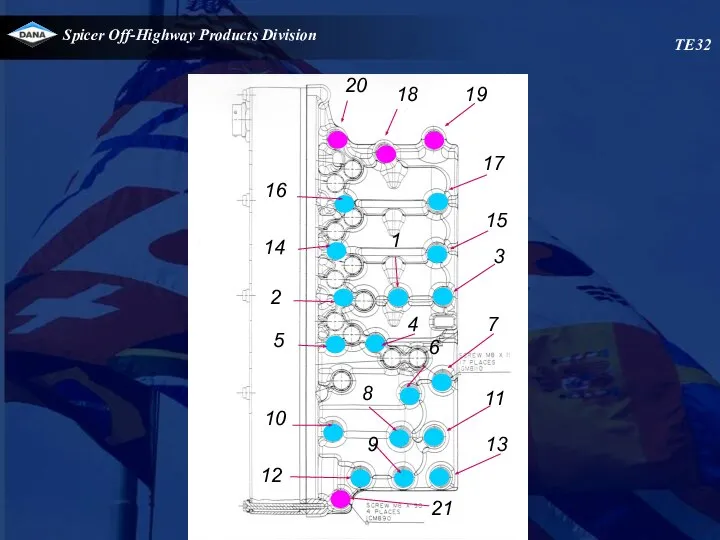
- 99. TE32 20 18 19 17 15 3 7 11 13 16 14 2 5 10 12
- 100. TE 32 Speed sensor installation
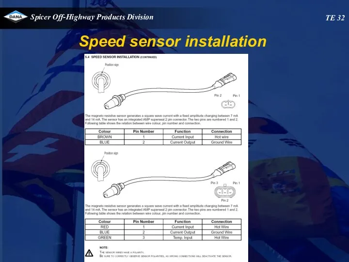
- 101. TE 32 Speed sensor installation
- 102. TE 32 Speed sensor installation
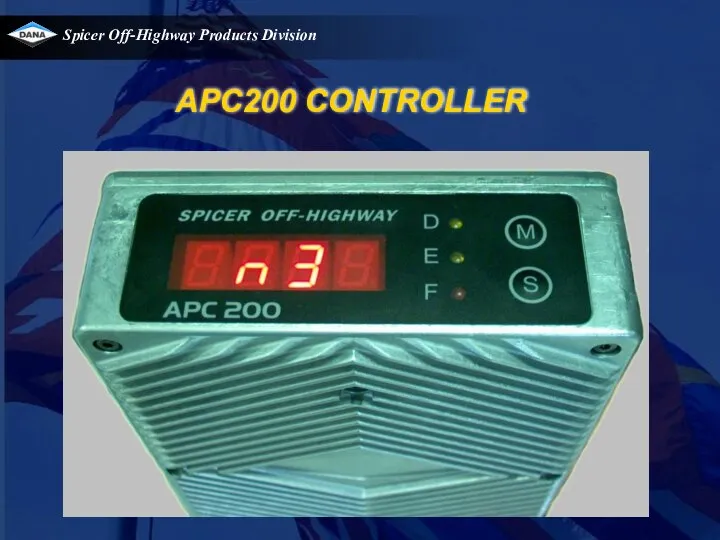
- 103. APC200 CONTROLLER
- 104. Overview Link with the transmission APC200 APC200 display modes APC200 diagnostics System calibration
- 105. Transmission Input signals Speed sensors Engine speed Turbine speed Drum speed Output speed Pressure feedback switch
- 106. Control valve Proportional solenoids (VFS = “Variable Force Solenoid”) VFS0 for forward VFS1 for 2nd/4th (if
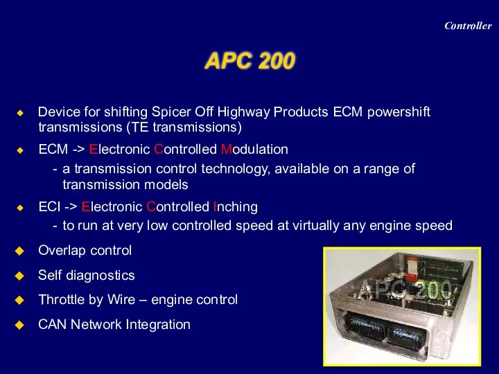
- 107. APC 200 Device for shifting Spicer Off Highway Products ECM powershift transmissions (TE transmissions) ECM ->
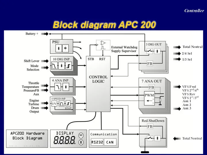
- 108. Block diagram APC 200 Controller
- 109. Block diagram APC 200 : inputs Controller 10 digital inputs 6 (7) analogue inputs Ani0 Pressure
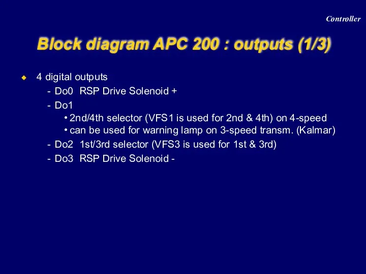
- 110. Block diagram APC 200 : outputs (1/3) Controller 4 digital outputs Do0 RSP Drive Solenoid +
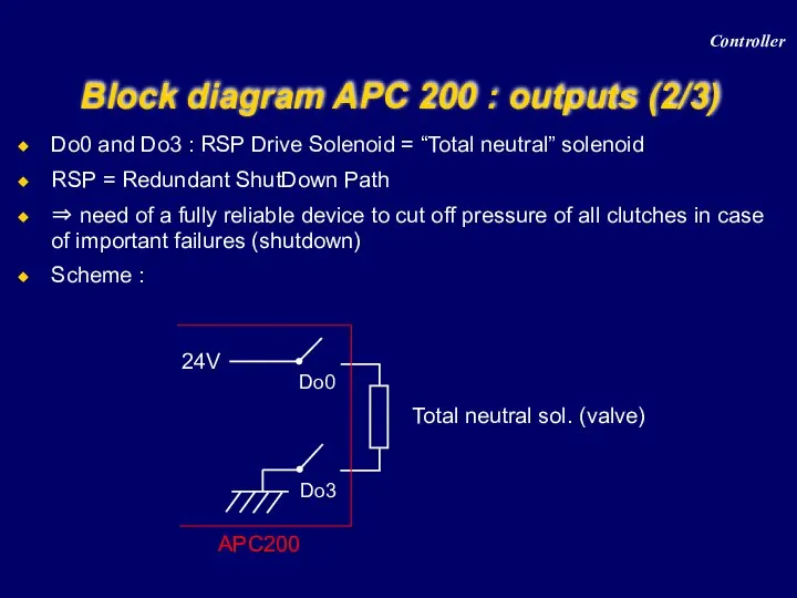
- 111. Block diagram APC 200 : outputs (2/3) Controller Do0 and Do3 : RSP Drive Solenoid =
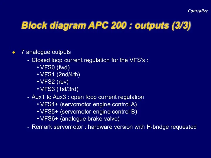
- 112. Block diagram APC 200 : outputs (3/3) Controller 7 analogue outputs Closed loop current regulation for
- 113. Block diagram APC 200 : example Controller
- 114. PSU = Power Supply Unit Version : 12V or 24V Two power lines PPWR : permanent
- 115. Bootstrap and reset circuit Bootstrap: Special mode, controller wants to receive serial data, to program the
- 116. Functions Manual / automatic shifting Electronic modulation Overlap control Electronic inching Start 1st / 2nd Limit
- 117. Functions on wiring diagram Controller
- 118. Communication CAN 2.0 B Communicate with different controllers and PC RS 232 To flash a new
- 119. Parameter setting 1 approved drive-line = 1 APT-file Approved drive-line = Specific type of vehicle +
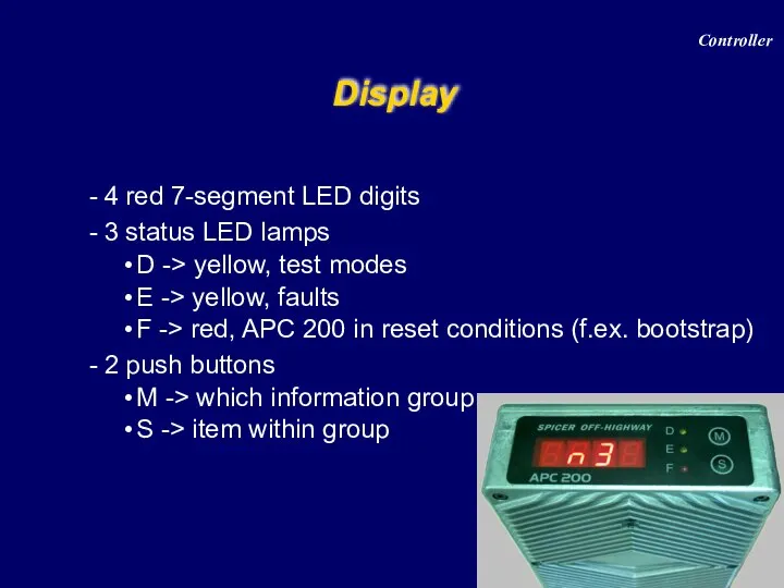
- 120. Display 4 red 7-segment LED digits 3 status LED lamps D -> yellow, test modes E
- 121. Display modes Controller
- 122. “GPOS” display Reflects the actually engaged transmission direction and range Display modes Controller
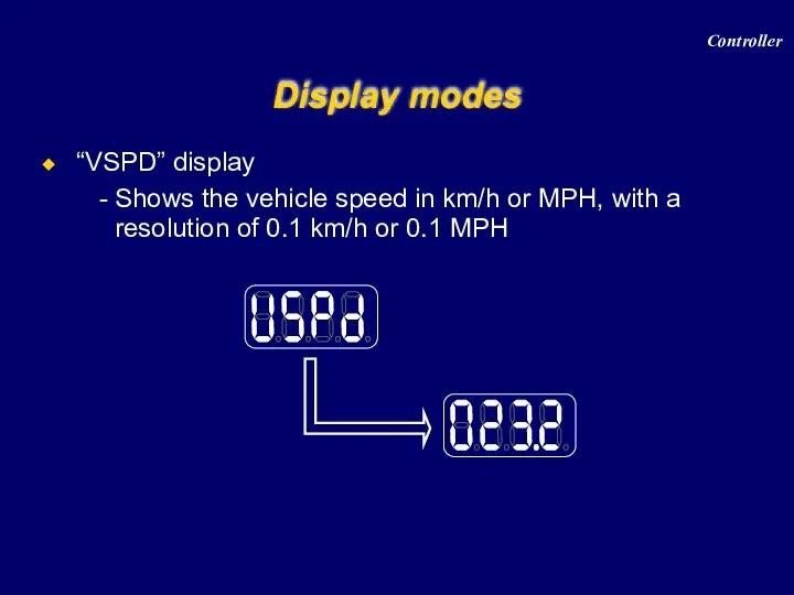
- 123. Display modes “VSPD” display Shows the vehicle speed in km/h or MPH, with a resolution of
- 124. “dist” display Shows the distance travelled in km or miles, with a resolution of 0.1 km
- 125. Display modes Controller
- 126. “CPOS” display Reflects the actually shiftlever position Display modes Controller
- 127. “Espd” display Shows the measured engine speed in RPM Display modes Controller
- 128. “Tspd” display Shows the measured turbine speed in RPM Display modes Controller
- 129. “Ospd” display Shows the measured output speed in RPM Display modes Controller
- 130. “Srat” display Reflects the current speed ration ( Tspd / Espd ), which is an important
- 131. “TQ I” display Reflects the measured torque (turbine torque) at the transmission input side in Nm
- 132. “Ttmp” display Shows the transmission sump temperature in °C Display modes Controller
- 133. “Ctmp” display Shows the Converter out temperature in °C Display modes Note : due that the
- 134. Display modes Controller
- 135. “Err” display Shows all existing error codes (none blinking error code) and error codes detected in
- 136. Error codes list Controller
- 137. Diagnostics Controller
- 138. Diagnostics Note : for the firmware version, the display is using a scrolling text moving to
- 139. Diagnostics Digital input test Digital input reference 0 1 2 3 4 5 8 9 6
- 140. Diagnostics Analog input test 1st value (kΩ or V) of the 1st 4 analog inputs No
- 141. Diagnostics Speed sensor test C informs the sensor is a current sensor, value is expressed in
- 142. Diagnostics Output test Analog output Current of 997 mA Analog output 3 on wire 8 Note
- 143. Diagnostics Voltage test Voltage switched power Voltage sensor power supply 22.7 volt 8.1 volt Controller
- 144. Calibration APC200-Transmission Menu structure overview Transmission calibration (clutch filling) Heat mode Calibration of the analogue inputs
- 145. Menu structure overview
- 146. Transmission calibration (clutch filling) Introduction What? Is determining volume of oil that is needed to fill
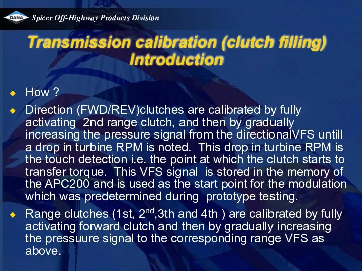
- 147. Transmission calibration (clutch filling) Introduction How ? Direction (FWD/REV)clutches are calibrated by fully activating 2nd range
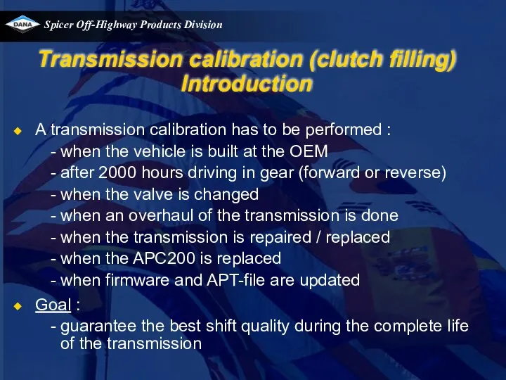
- 148. Transmission calibration (clutch filling) Introduction A transmission calibration has to be performed : when the vehicle
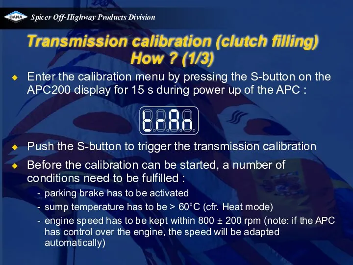
- 149. Transmission calibration (clutch filling) How ? (1/3) Enter the calibration menu by pressing the S-button on
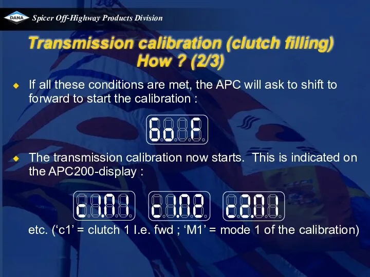
- 150. Transmission calibration (clutch filling) How ? (2/3) If all these conditions are met, the APC will
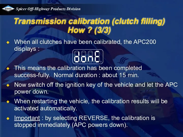
- 151. Transmission calibration (clutch filling) How ? (3/3) When all clutches have been calibrated, the APC200 displays
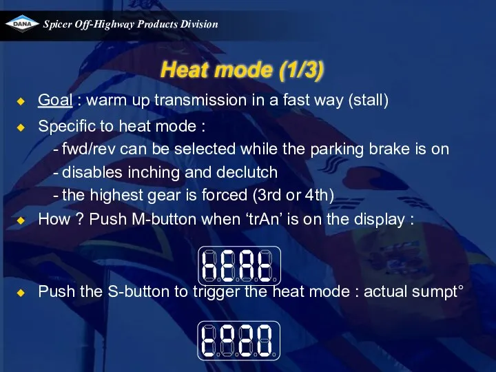
- 152. Heat mode (1/3) Goal : warm up transmission in a fast way (stall) Specific to heat
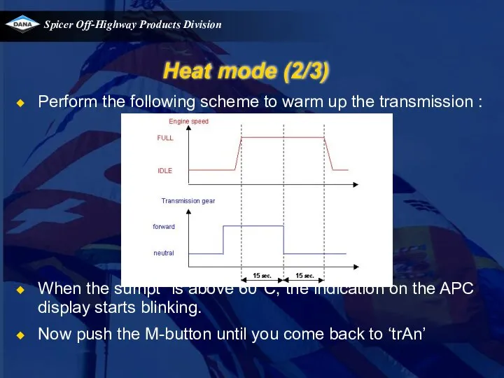
- 153. Heat mode (2/3) Perform the following scheme to warm up the transmission : When the sumpt°
- 154. Heat mode (3/3) Note : When the converter out temperature would exceed 120°C, the engine speed
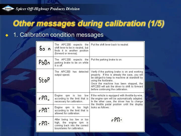
- 155. Other messages during calibration (1/5) 1. Calibration condition messages
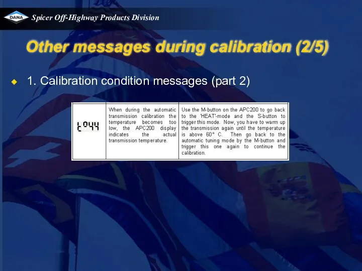
- 156. Other messages during calibration (2/5) 1. Calibration condition messages (part 2)
- 157. Other messages during calibration (3/5) 2. Calibration error messages E1.25 : during calibration, early touch detect.
- 158. Other messages during calibration (4/5) 2. Calibration error messages continued E1.10 : during calibration, shift inhibit.
- 159. Other messages during calibration (5/5) 2. Calibration error messages continued E2.14 : calibration failed ,fill time
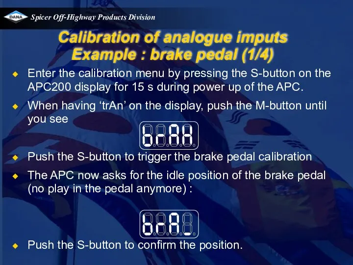
- 160. Calibration of analogue imputs Example : brake pedal (1/4) Enter the calibration menu by pressing the
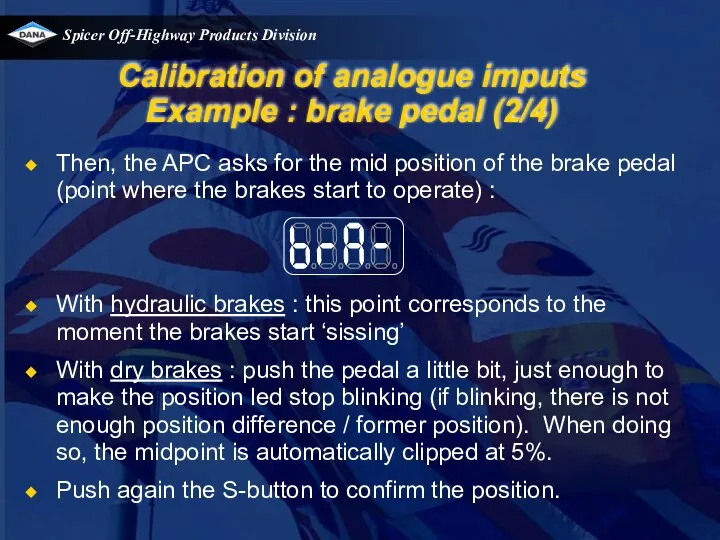
- 161. Calibration of analogue imputs Example : brake pedal (2/4) Then, the APC asks for the mid
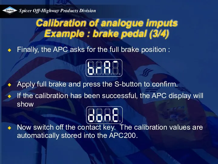
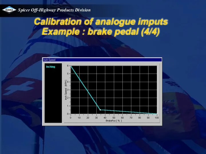
- 162. Calibration of analogue imputs Example : brake pedal (3/4) Finally, the APC asks for the full
- 163. Calibration of analogue imputs Example : brake pedal (4/4)
- 164. TE transmission field experience TE13/17 field campaign Speed sensor changes Case studies
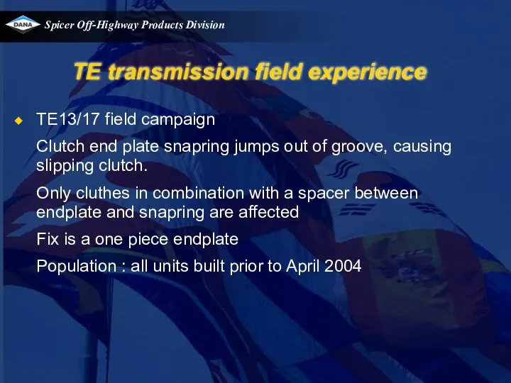
- 165. TE transmission field experience TE13/17 field campaign Clutch end plate snapring jumps out of groove, causing
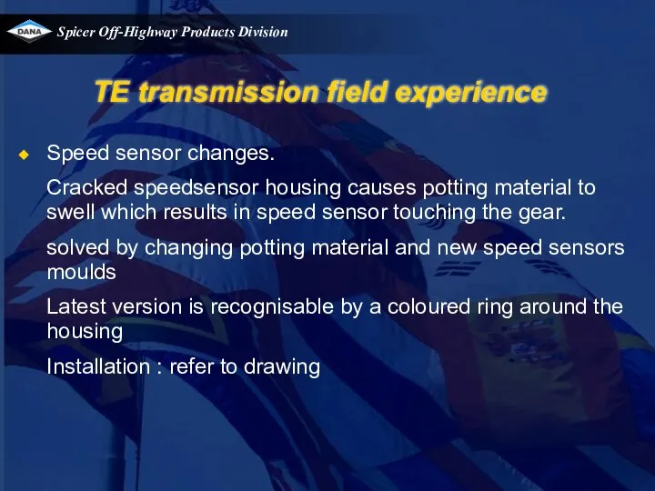
- 166. TE transmission field experience Speed sensor changes. Cracked speedsensor housing causes potting material to swell which
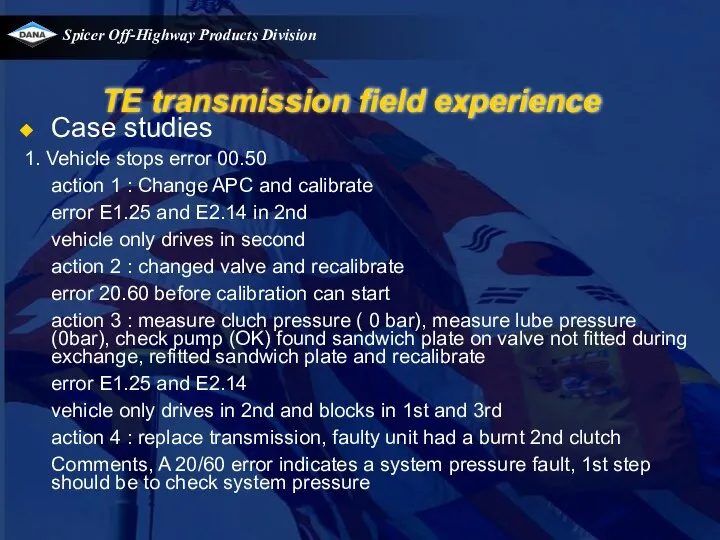
- 167. TE transmission field experience Case studies 1. Vehicle stops error 00.50 action 1 : Change APC
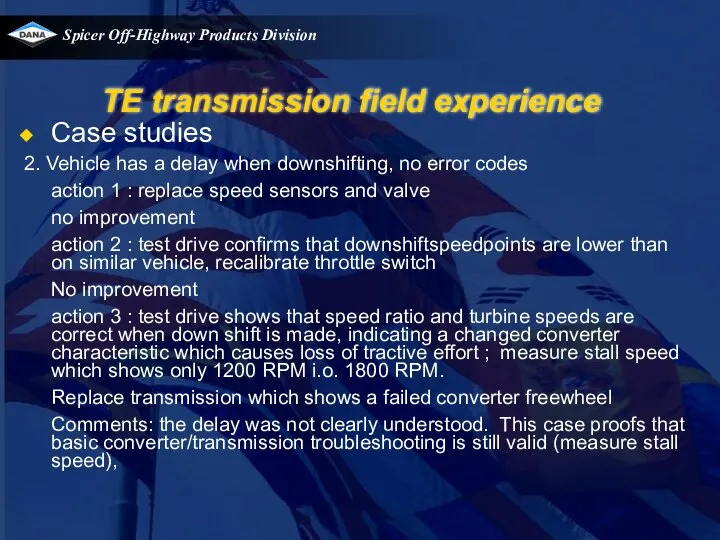
- 168. TE transmission field experience Case studies 2. Vehicle has a delay when downshifting, no error codes
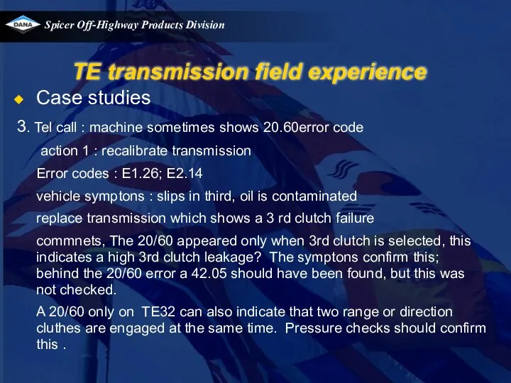
- 169. TE transmission field experience Case studies 3. Tel call : machine sometimes shows 20.60error code action
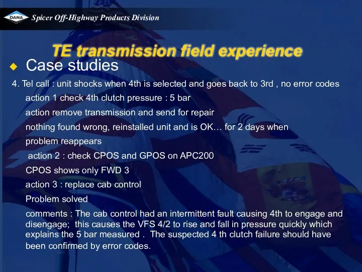
- 170. TE transmission field experience Case studies 4. Tel call : unit shocks when 4th is selected
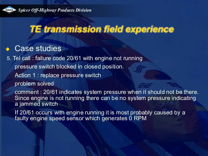
- 171. TE transmission field experience Case studies 5. Tel call : failure code 20/61 with engine not
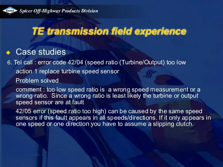
- 172. TE transmission field experience Case studies 6. Tel call : error code 42/04 (speed ratio (Turbine/Output)
- 174. Скачать презентацию
Basic connverter /transmission theory
movie
Basic connverter /transmission theory
movie
TE transmissions
Electronic controlled modulation
Clutch overlap control
Inching control
TE transmissions
Electronic controlled modulation
Clutch overlap control
Inching control
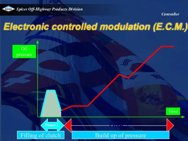
Electronic controlled modulation (E.C.M.)
Controller
Electronic controlled modulation (E.C.M.)
Controller
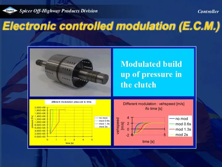
Modulated build up of pressure in the clutch
Electronic controlled modulation (E.C.M.)
Controller
Modulated build up of pressure in the clutch
Electronic controlled modulation (E.C.M.)
Controller
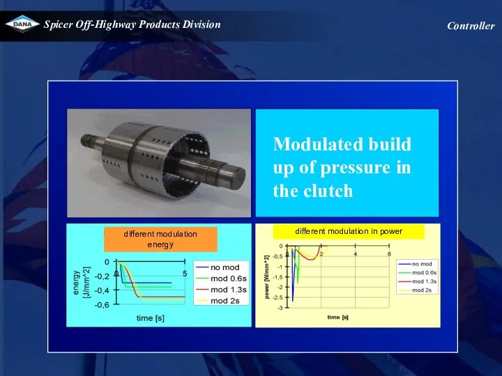
Modulated build up of pressure in the clutch
Controller
different modulation
energy
different modulation in
Modulated build up of pressure in the clutch
Controller
different modulation
energy
different modulation in
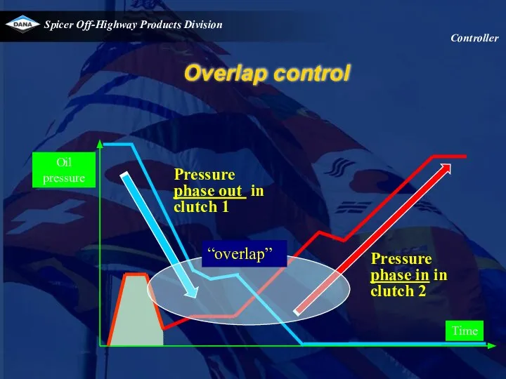
Overlap control
Controller
Overlap control
Controller
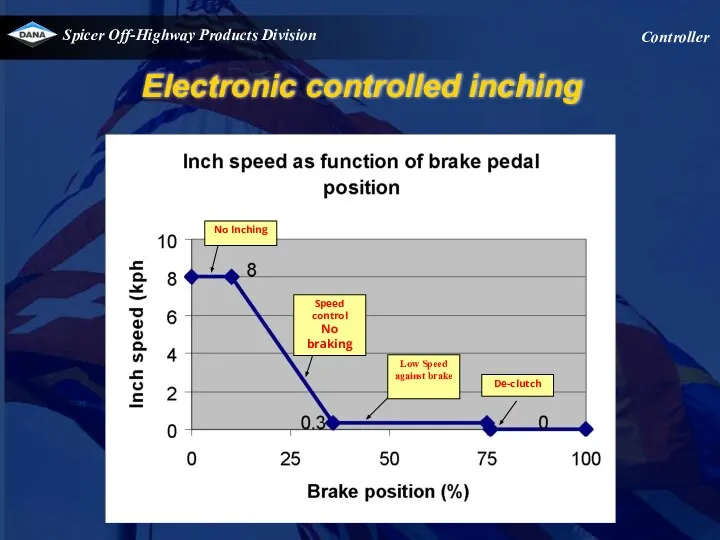
Electronic controlled inching
Controller
Electronic controlled inching
Controller
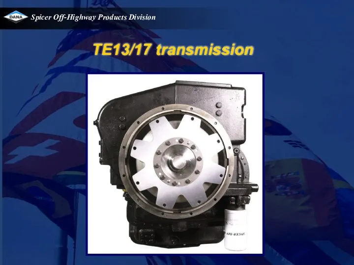
TE13/17 transmission
TE13/17 transmission
TE 13 & TE17
TE 13 & TE17
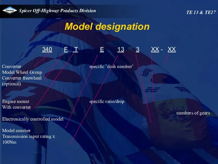
340 F T E 13 3 XX - XX
Converter specific ¨dash
340 F T E 13 3 XX - XX
Converter specific ¨dash
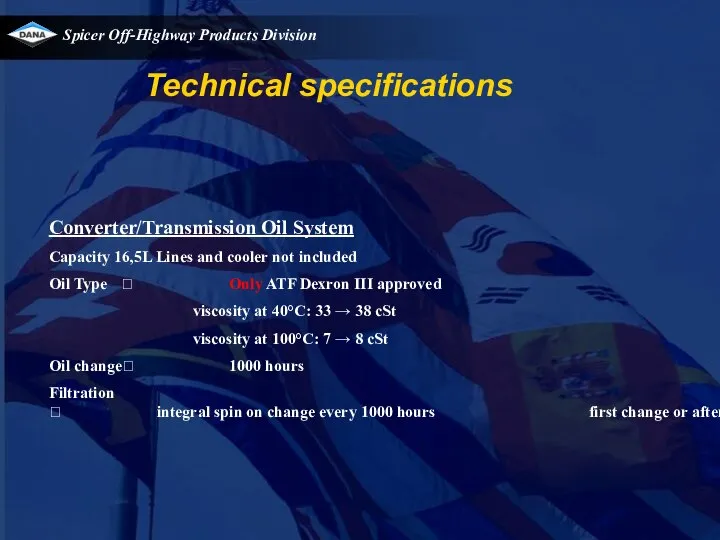
Converter/Transmission Oil System
Capacity 16,5L Lines and cooler not included
Oil Type ? Only
Converter/Transmission Oil System
Capacity 16,5L Lines and cooler not included
Oil Type ? Only
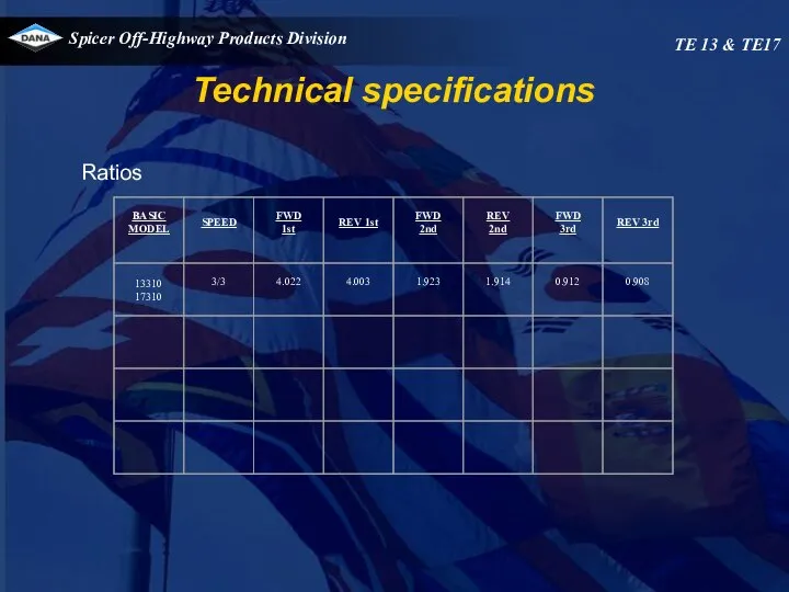
Ratios
Technical specifications
TE 13 & TE17
Ratios
Technical specifications
TE 13 & TE17
Temperature specifications
Normal operating temperature 70 - 120°C at temperature check port
Temperature specifications
Normal operating temperature 70 - 120°C at temperature check port
At 2200 RPM 24
–
29 Bar
Converter : 1.0 -4.0 l/m
Each range
At 2200 RPM 24
–
29 Bar
Converter : 1.0 -4.0 l/m
Each range
Safety valve
cracking pressure 7,5 bar
Converter out pressure (to cooler)
3.0 – 3.5
Safety valve
cracking pressure 7,5 bar
Converter out pressure (to cooler)
3.0 – 3.5
Pump flow
At 2200 RPM : 90 to 110 lpm
TE 13 &
Pump flow
At 2200 RPM : 90 to 110 lpm
TE 13 &
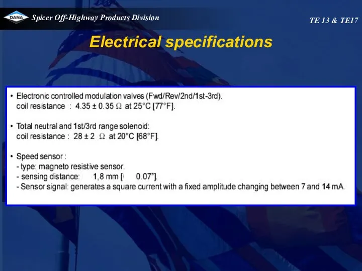
Electrical specifications
TE 13 & TE17
Electrical specifications
TE 13 & TE17
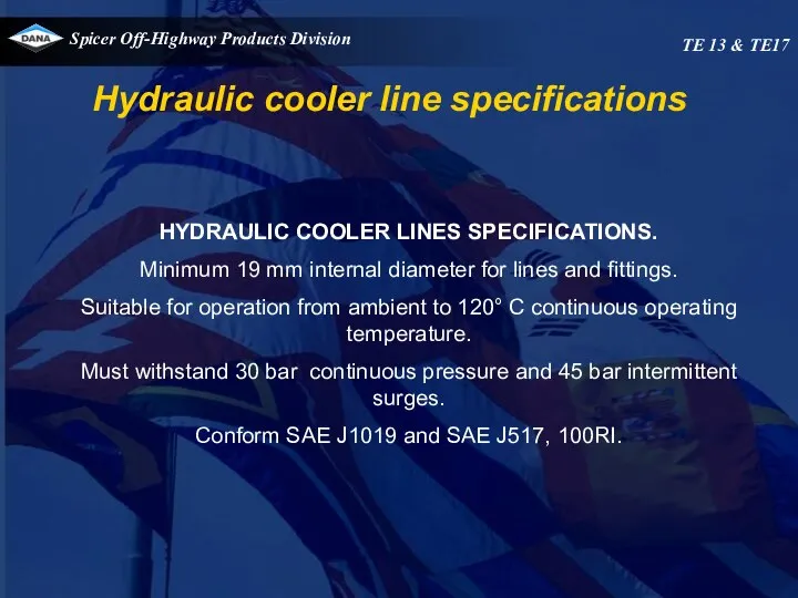
HYDRAULIC COOLER LINES SPECIFICATIONS.
Minimum 19 mm internal diameter for lines and
HYDRAULIC COOLER LINES SPECIFICATIONS.
Minimum 19 mm internal diameter for lines and
TE 13 & TE17
TE 13 & TE17
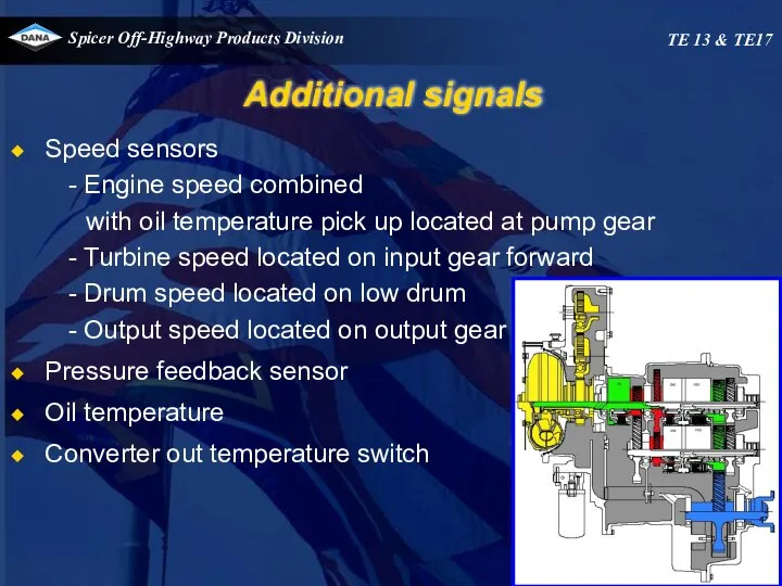
Additional signals
Speed sensors
Engine speed combined
with oil temperature pick up
Additional signals
Speed sensors
Engine speed combined
with oil temperature pick up
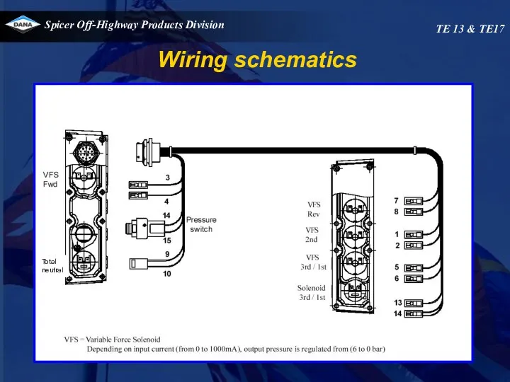
Wiring schematics
TE 13 & TE17
Total
neutral
Wiring schematics
TE 13 & TE17
Total
neutral
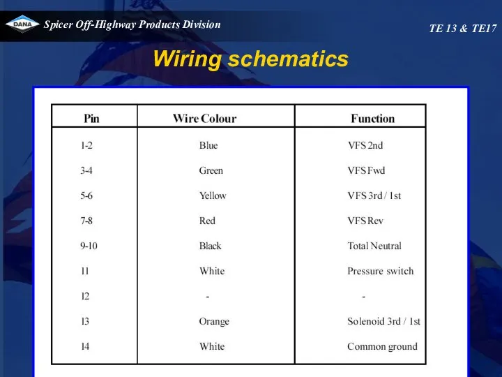
Wiring schematics
TE 13 & TE17
Wiring schematics
TE 13 & TE17
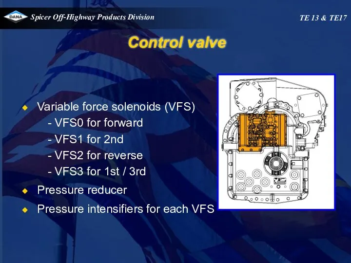
Control valve
Variable force solenoids (VFS)
VFS0 for forward
VFS1 for 2nd
VFS2 for reverse
VFS3
Control valve
Variable force solenoids (VFS)
VFS0 for forward
VFS1 for 2nd
VFS2 for reverse
VFS3
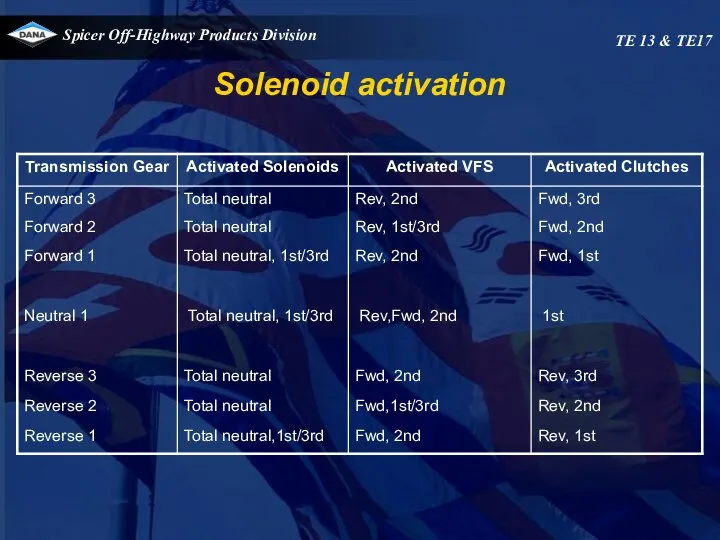
Solenoid activation
TE 13 & TE17
Solenoid activation
TE 13 & TE17
Electronic controlled modulation (E.C.M.)
TE13-17
Electronic controlled modulation (E.C.M.)
TE13-17
Operation of transmission
TE 13 & TE17
The transmission is controlled by an
Operation of transmission
TE 13 & TE17
The transmission is controlled by an
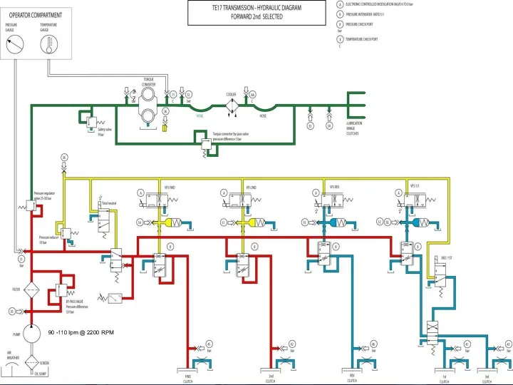
Operation of transmission
TE 13 & TE17
Range selection
When 1 st clutch is
Operation of transmission
TE 13 & TE17
Range selection
When 1 st clutch is
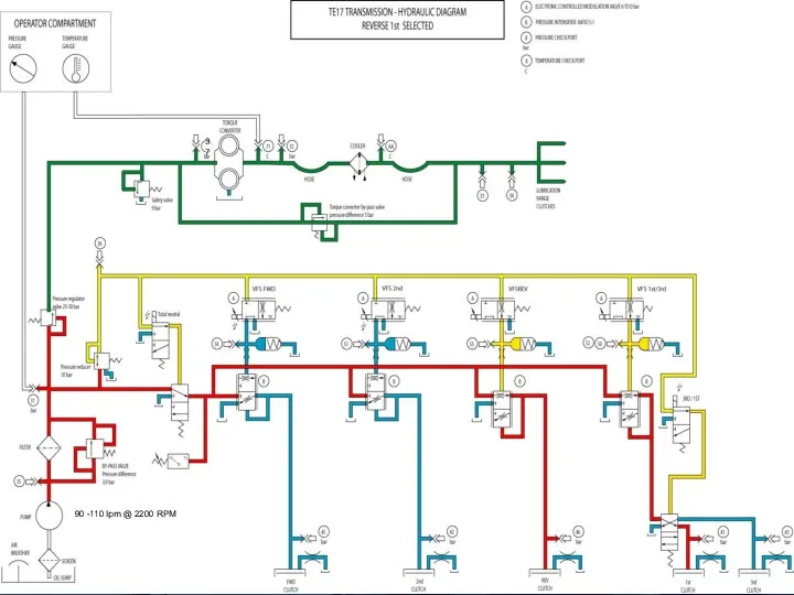
Operation of transmission
TE 13 & TE17
Total neutral selection
Total neutral is only
Operation of transmission
TE 13 & TE17
Total neutral selection
Total neutral is only
TE 13 & TE17
37
90 -110 lpm @ 2200 RPM
TE 13 & TE17
37
90 -110 lpm @ 2200 RPM
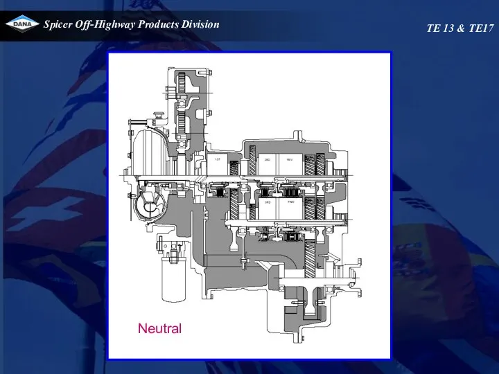
Neutral
TE 13 & TE17
Neutral
TE 13 & TE17
TE 13 & TE17
90 -110 lpm @ 2200 RPM
37
TE 13 & TE17
90 -110 lpm @ 2200 RPM
37
TE 13 & TE17
TE 13 & TE17
TE 13 & TE17
90 -110 lpm @ 2200 RPM
37
TE 13 & TE17
90 -110 lpm @ 2200 RPM
37
TE 13 & TE17
TE 13 & TE17

TE 13 & TE17
90 -110 lpm @ 2200 RPM
37
TE 13 & TE17
90 -110 lpm @ 2200 RPM
37
TE 13 & TE17
TE 13 & TE17
TE 13 & TE17
90 -110 lpm @ 2200 RPM
37
TE 13 & TE17
90 -110 lpm @ 2200 RPM
37
TE 13 & TE17
TE 13 & TE17
Check ports
TE 13 & TE17
Check ports
TE 13 & TE17
Check ports
TE 13 & TE17
Port 42 2nd clutch
Port 46
Pressure check
Check ports
TE 13 & TE17
Port 42 2nd clutch
Port 46
Pressure check
Check ports
TE 13 & TE17
To cooler
Port 37
Safety valve
pressure
Safaty valve
mmmpressure
Safaty
Check ports
TE 13 & TE17
To cooler
Port 37
Safety valve
pressure
Safaty valve
mmmpressure
Safaty
Check ports
TE 13 & TE17
Safaty valve
pressure
Engine
Check ports
TE 13 & TE17
Safaty valve
pressure
Engine
Check ports
TE 13 & TE17
Port 46
Rev. clutch
Rev. clutch
Pump
Pressure
Port 35
Check ports
TE 13 & TE17
Port 46
Rev. clutch
Rev. clutch
Pump
Pressure
Port 35
Check ports
TE 13 & TE17
Pressure
To cooler
Port 32
Check ports
TE 13 & TE17
Pressure
To cooler
Port 32
Check ports Control valve
TE 13 & TE17
VFS REV
Port 55
VFS 2nd
Port
Check ports Control valve
TE 13 & TE17
VFS REV
Port 55
VFS 2nd
Port
Control valve installation instruction
Removing the valve
1.Make sure that the area around
Control valve installation instruction
Removing the valve
1.Make sure that the area around
Control valve installation instruction
Installing the valve
1.Unscrew the 7bolts (marked green with
Control valve installation instruction
Installing the valve
1.Unscrew the 7bolts (marked green with
27*
26*
15*
16
18
25
24
22
12
20
21
23*
5
4
11
19
13
6
1*
3
10*
9*
14
7
2
8
17
Control valve installation instruction
TE 13 & TE17
27*
26*
15*
16
18
25
24
22
12
20
21
23*
5
4
11
19
13
6
1*
3
10*
9*
14
7
2
8
17
Control valve installation instruction
TE 13 & TE17
Control valve installation instruction
TE 13 & TE17
15
9
8
7
10
11
12
13
14
6
5
4
3
2
1
Control valve installation instruction
TE 13 & TE17
15
9
8
7
10
11
12
13
14
6
5
4
3
2
1
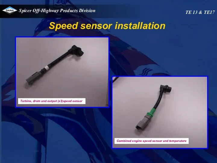
Speed sensor installation
TE 13 & TE17
Combined engine speed sensor and temperature
Turbine,
Speed sensor installation
TE 13 & TE17
Combined engine speed sensor and temperature
Turbine,
Speed sensor installation
TE 13 & TE17
Speed sensor installation
TE 13 & TE17
Speed sensor installation
TE 13 & TE17
Speed sensor installation
TE 13 & TE17
Speed sensor installation
TE 13 & TE17
Speed sensor installation
TE 13 & TE17
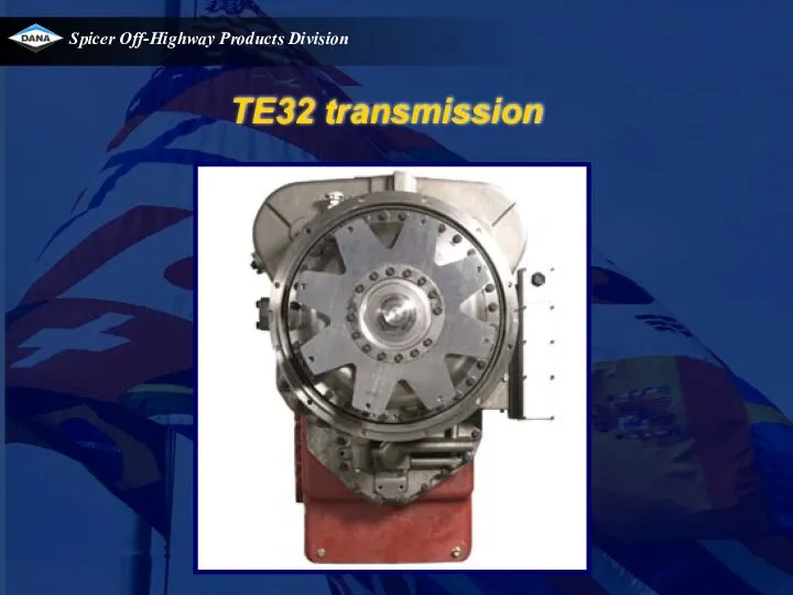
TE32 transmission
TE32 transmission
Overview
TE32
TE32 :
short drop
4 speed Fwd/Rev
Overview
TE32
TE32 :
short drop
4 speed Fwd/Rev
TE32
Transmission
Layout
TE32
Transmission
Layout
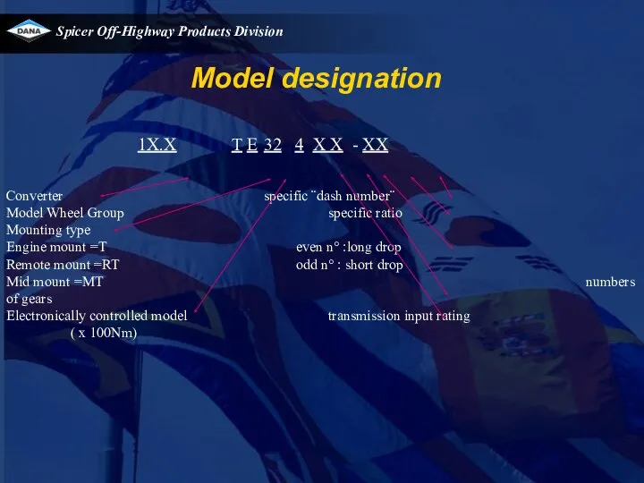
1X.X T E 32 4 X X - XX
Converter specific ¨dash number¨
Model
1X.X T E 32 4 X X - XX
Converter specific ¨dash number¨
Model
TE32
Technical specifications
Ratio TE32418
TE32
Technical specifications
Ratio TE32418
TE32
Technical specifications
Output flange rotation – (transmission forward clutch
TE32
Technical specifications
Output flange rotation – (transmission forward clutch
Speed pick-up :
- Engine speed combined with temperature located on
Speed pick-up :
- Engine speed combined with temperature located on
TE32
Technical specifications
Converter/Transmission Oil System
Capacity (Approximate: measured at
TE32
Technical specifications
Converter/Transmission Oil System
Capacity (Approximate: measured at
Normal operating temperature 70 - 120°C at temperature check port converter
Normal operating temperature 70 - 120°C at temperature check port converter
At 1800 RPM 20.5 - 24.5 bar
Fwd/Rev max 4 l/min
1st max
At 1800 RPM 20.5 - 24.5 bar
Fwd/Rev max 4 l/min
1st max
Savety valve
cracking pressure 8.8-9.6 bar
Converter out pressure (to cooler)
5 bar min.
Savety valve
cracking pressure 8.8-9.6 bar
Converter out pressure (to cooler)
5 bar min.
Variable force solenoids(VFS)
VFS 2nd/4th - VFS 1st/3rd - VFS Fwd -VFS
Variable force solenoids(VFS)
VFS 2nd/4th - VFS 1st/3rd - VFS Fwd -VFS
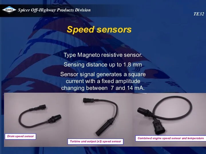
Speed sensors
Type Magneto resistive sensor.
Sensing distance up to 1.8 mm
Sensor
Speed sensors
Type Magneto resistive sensor.
Sensing distance up to 1.8 mm
Sensor

HYDRAULIC COOLER LINES SPECIFICATIONS.
Minimum 32 mm internal diameter for lines and
HYDRAULIC COOLER LINES SPECIFICATIONS.
Minimum 32 mm internal diameter for lines and
TE32
TE32
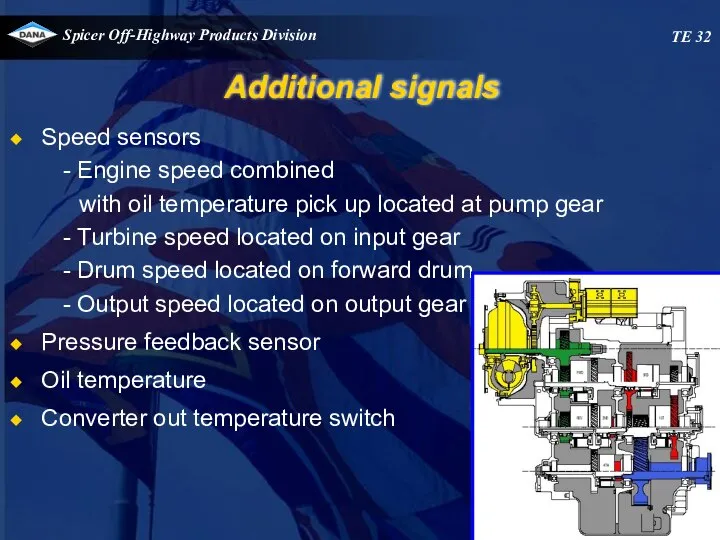
Additional signals
Speed sensors
Engine speed combined
with oil temperature pick up
Additional signals
Speed sensors
Engine speed combined
with oil temperature pick up
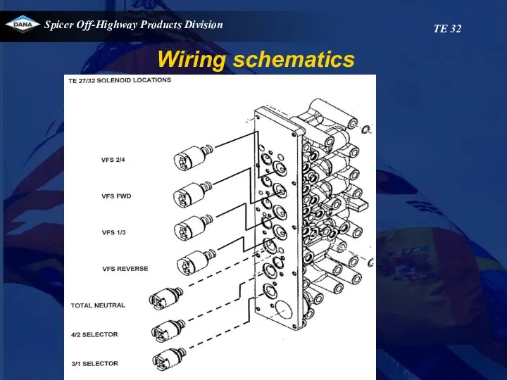
Wiring schematics
TE 32
Wiring schematics
TE 32
Wiring schematics
TE 32
Wiring schematics
TE 32
TE32
Solenoids activated
Transmission
gear
Forward 4
Forward 3
Forward 2
Forward 1
Neutral 4
Neutral 3
Neutral 2
Neutral 1
Reverse
TE32
Solenoids activated
Transmission gear Forward 4 Forward 3 Forward 2 Forward 1 Neutral 4 Neutral 3 Neutral 2 Neutral 1 Reverse

Electronic controlled modulation (E.C.M.)
TE27-32
Electronic controlled modulation (E.C.M.)
TE27-32
Operation of transmission
TE32
The transmission is controlled by an APC200 box. This
Operation of transmission
TE32
The transmission is controlled by an APC200 box. This
Operation of transmission
TE32
Range selection
When 1 st clutch is selected , the
Operation of transmission
TE32
Range selection
When 1 st clutch is selected , the
Operation of transmission
TE32
Neutral selection
When neutral is selected (1st, 2nd, 3rd
Operation of transmission
TE32
Neutral selection
When neutral is selected (1st, 2nd, 3rd
Operation of transmission
TE32
Pressure switch
The control valve also has a pressure
Operation of transmission
TE32
Pressure switch
The control valve also has a pressure
TE32
VFS 1/3
VFS 2/4
TE32
VFS 1/3
VFS 2/4
TE32
Total neutral
TE32
Total neutral
TE32
VFS 1/3
VFS 2/4
TE32
VFS 1/3
VFS 2/4
TE32
Forward 1st
TE32
Forward 1st
TE32
VFS 1/3
VFS 2/4
TE32
VFS 1/3
VFS 2/4
TE32
Forward 2nd
TE32
Forward 2nd
TE32
VFS 1/3
VFS 2/4
TE32
VFS 1/3
VFS 2/4

TE32
Forward 3rd
TE32
Forward 3rd
TE32
VFS 1/3
VFS 2/4
TE32
VFS 1/3
VFS 2/4
TE32
Forward 4th
TE32
Forward 4th
TE32
VFS 1/3
VFS 2/4
TE32
VFS 1/3
VFS 2/4
TE32
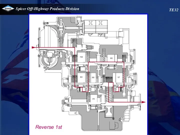
Reverse 1st
TE32
Reverse 1st
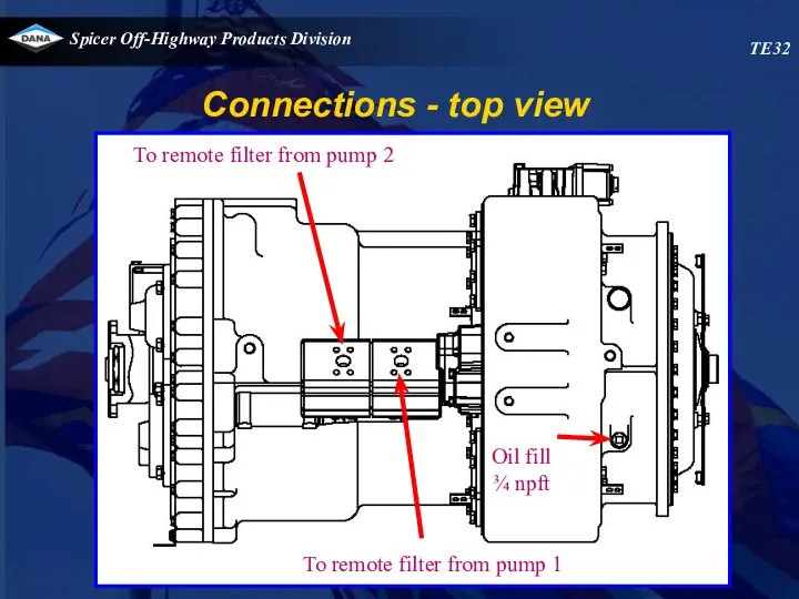
Connections - top view
To remote filter from pump 2
To
Connections - top view
To remote filter from pump 2
To
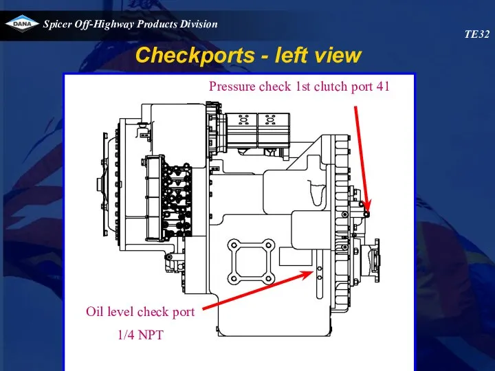
Pressure check 1st clutch port 41
Oil level check port
1/4 NPT
Checkports
Pressure check 1st clutch port 41
Oil level check port
1/4 NPT
Checkports
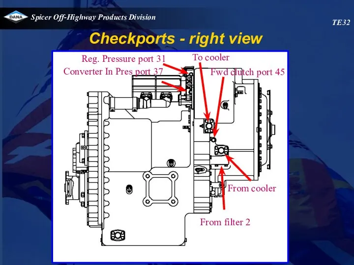
Checkports - right view
TE32
Reg. Pressure port 31
Converter In Pres
Checkports - right view
TE32
Reg. Pressure port 31
Converter In Pres
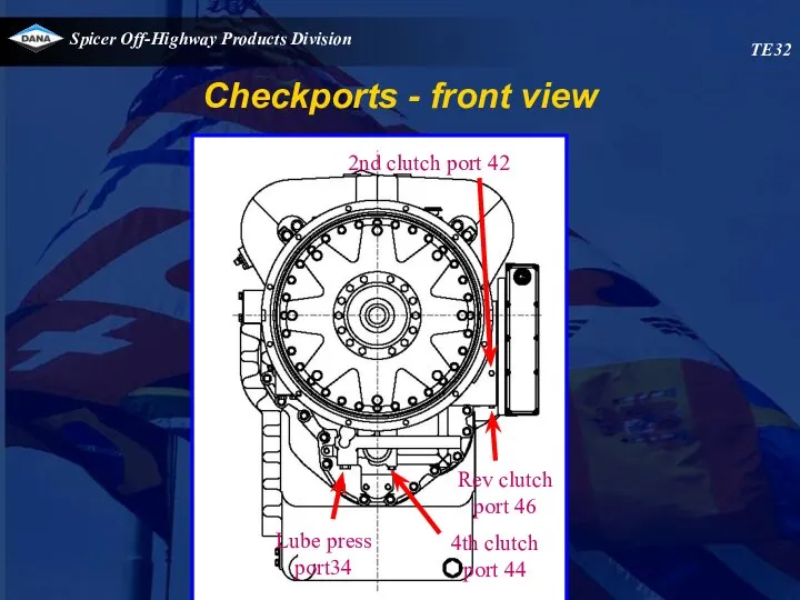
Checkports - front view
TE32
2nd clutch port 42
Rev clutch
port 46
4th clutch
port 44
Lube
Checkports - front view
TE32
2nd clutch port 42
Rev clutch
port 46
4th clutch
port 44
Lube
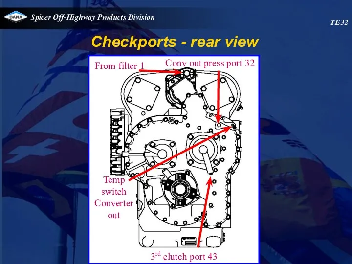
Checkports - rear view
TE32
From filter 1
Conv out press port 32
Temp switch
Converter
Checkports - rear view
TE32
From filter 1
Conv out press port 32
Temp switch
Converter
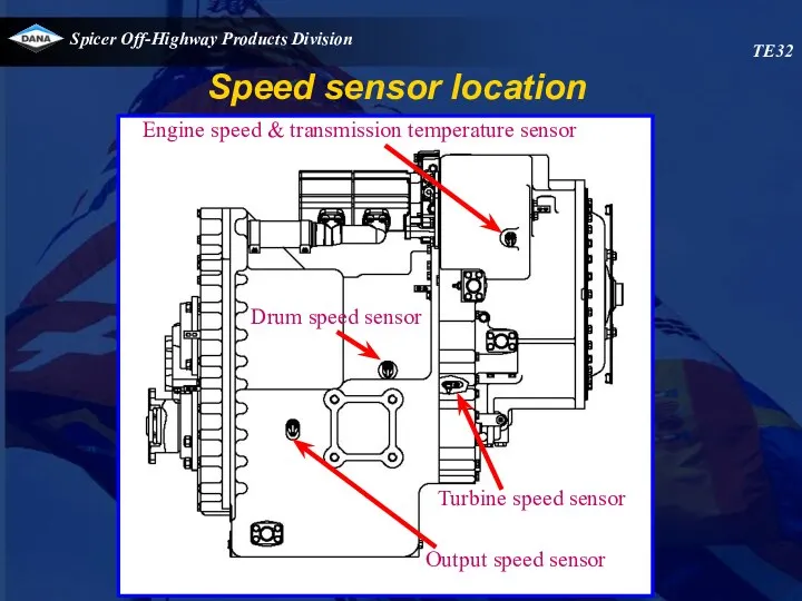
Speed sensor location
TE32
Engine speed & transmission temperature sensor
Drum speed sensor
Speed sensor location
TE32
Engine speed & transmission temperature sensor
Drum speed sensor
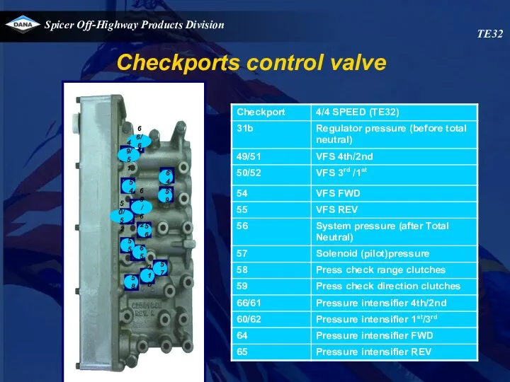
Checkports control valve
66/61
49/51
F
54
59
58
31b
57
65
55
56
50/52
60/62
64
TE32
Checkports control valve
66/61
49/51
F
54
59
58
31b
57
65
55
56
50/52
60/62
64
TE32
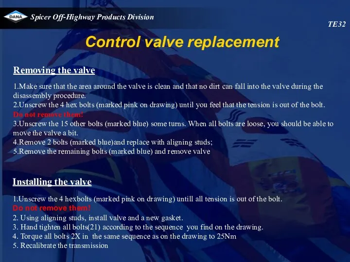
Control valve replacement
Removing the valve
1.Make sure that the area around the
Control valve replacement
Removing the valve
1.Make sure that the area around the
TE32
20
18
19
17
15
3
7
11
13
16
14
2
5
10
12
21
8
4
1
6
9
TE32
20
18
19
17
15
3
7
11
13
16
14
2
5
10
12
21
8
4
1
6
9
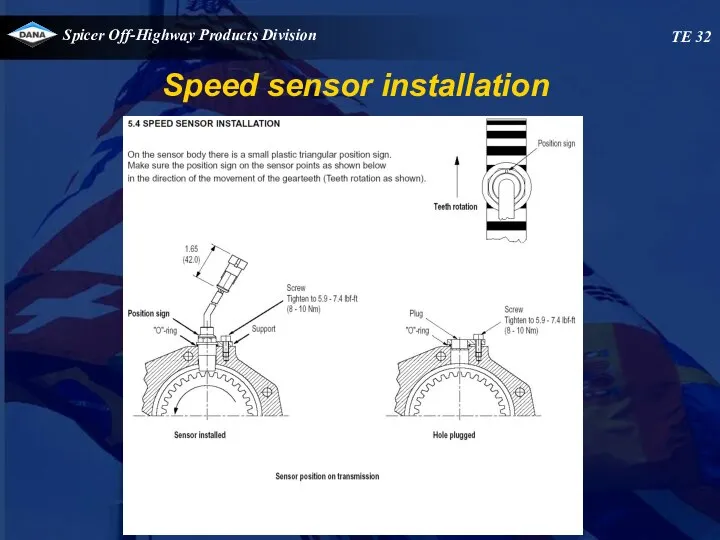
TE 32
Speed sensor installation
TE 32
Speed sensor installation
TE 32
Speed sensor installation
TE 32
Speed sensor installation

TE 32
Speed sensor installation
TE 32
Speed sensor installation
APC200 CONTROLLER
APC200 CONTROLLER
Overview
Link with the transmission
APC200
APC200 display modes
APC200 diagnostics
System calibration
Overview
Link with the transmission
APC200
APC200 display modes
APC200 diagnostics
System calibration
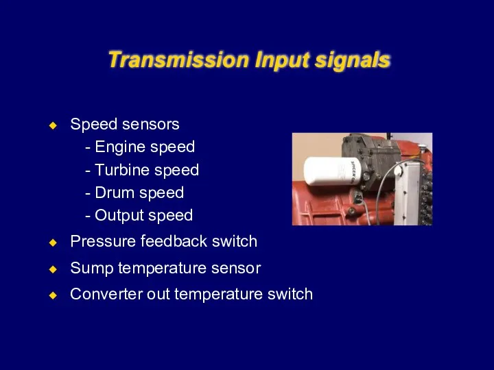
Transmission Input signals
Speed sensors
Engine speed
Turbine speed
Drum speed
Output speed
Pressure feedback switch
Sump
Transmission Input signals
Speed sensors
Engine speed
Turbine speed
Drum speed
Output speed
Pressure feedback switch
Sump
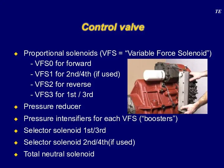
Control valve
Proportional solenoids (VFS = “Variable Force Solenoid”)
VFS0 for forward
VFS1 for
Control valve
Proportional solenoids (VFS = “Variable Force Solenoid”)
VFS0 for forward
VFS1 for
APC 200
Device for shifting Spicer Off Highway Products ECM powershift transmissions
APC 200
Device for shifting Spicer Off Highway Products ECM powershift transmissions
Block diagram APC 200
Controller
Block diagram APC 200
Controller

Block diagram APC 200 : inputs
Controller
10 digital inputs
6 (7) analogue inputs
Ani0
Block diagram APC 200 : inputs
Controller
10 digital inputs
6 (7) analogue inputs
Ani0
Block diagram APC 200 : outputs (1/3)
Controller
4 digital outputs
Do0 RSP Drive
Block diagram APC 200 : outputs (1/3)
Controller
4 digital outputs
Do0 RSP Drive
Block diagram APC 200 : outputs (2/3)
Controller
Do0 and Do3 : RSP
Block diagram APC 200 : outputs (2/3)
Controller
Do0 and Do3 : RSP
Block diagram APC 200 : outputs (3/3)
Controller
7 analogue outputs
Closed loop current
Block diagram APC 200 : outputs (3/3)
Controller
7 analogue outputs
Closed loop current
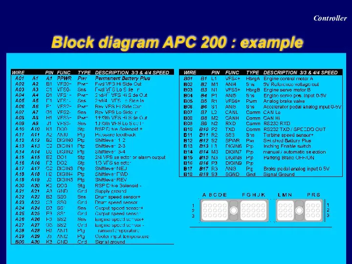
Block diagram APC 200 : example
Controller
Block diagram APC 200 : example
Controller
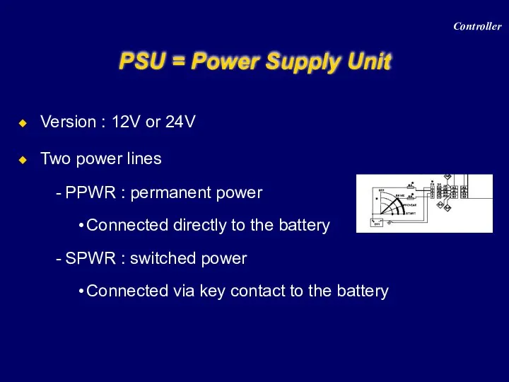
PSU = Power Supply Unit
Version : 12V or 24V
Two power lines
PPWR
PSU = Power Supply Unit
Version : 12V or 24V
Two power lines
PPWR
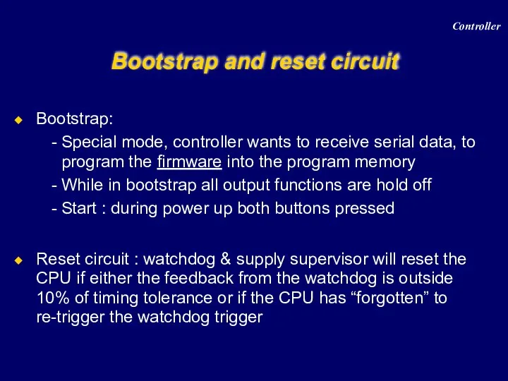
Bootstrap and reset circuit
Bootstrap:
Special mode, controller wants to receive serial data,
Bootstrap and reset circuit
Bootstrap:
Special mode, controller wants to receive serial data,
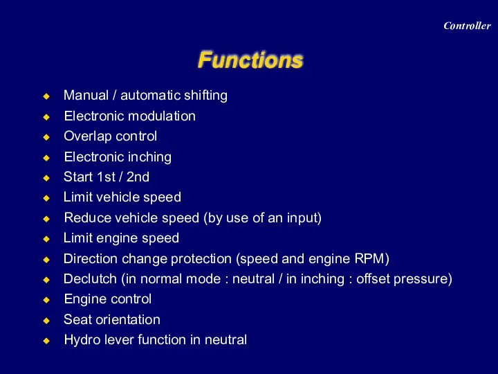
Functions
Manual / automatic shifting
Electronic modulation
Overlap control
Electronic inching
Start 1st / 2nd
Limit vehicle
Functions
Manual / automatic shifting
Electronic modulation
Overlap control
Electronic inching
Start 1st / 2nd
Limit vehicle
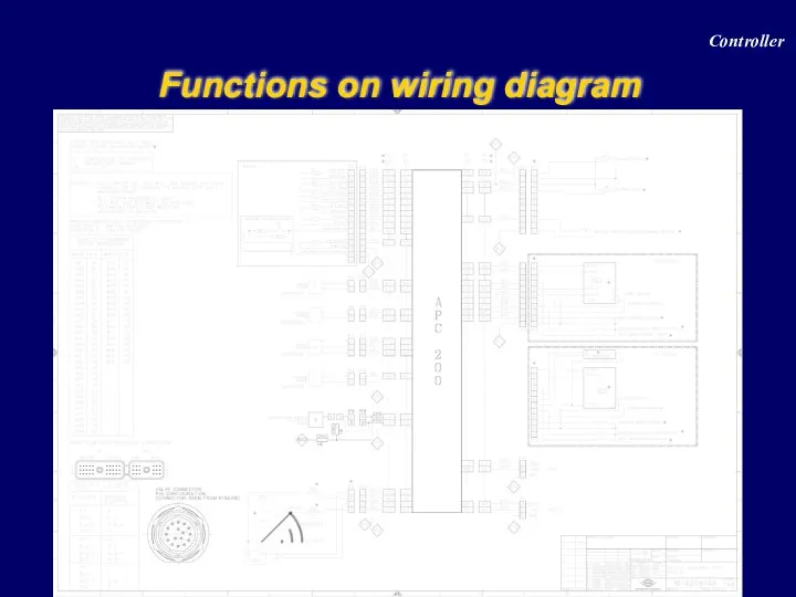
Functions on wiring diagram
Controller
Functions on wiring diagram
Controller
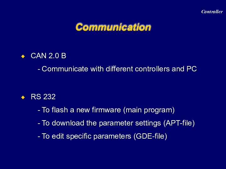
Communication
CAN 2.0 B
Communicate with different controllers and PC
RS 232
To flash a
Communication
CAN 2.0 B
Communicate with different controllers and PC
RS 232
To flash a
Parameter setting
1 approved drive-line = 1 APT-file
Approved drive-line =
Specific type
Parameter setting
1 approved drive-line = 1 APT-file
Approved drive-line =
Specific type
Display
4 red 7-segment LED digits
3 status LED lamps
D -> yellow,
Display
4 red 7-segment LED digits
3 status LED lamps
D -> yellow,

Display modes
Controller
Display modes
Controller
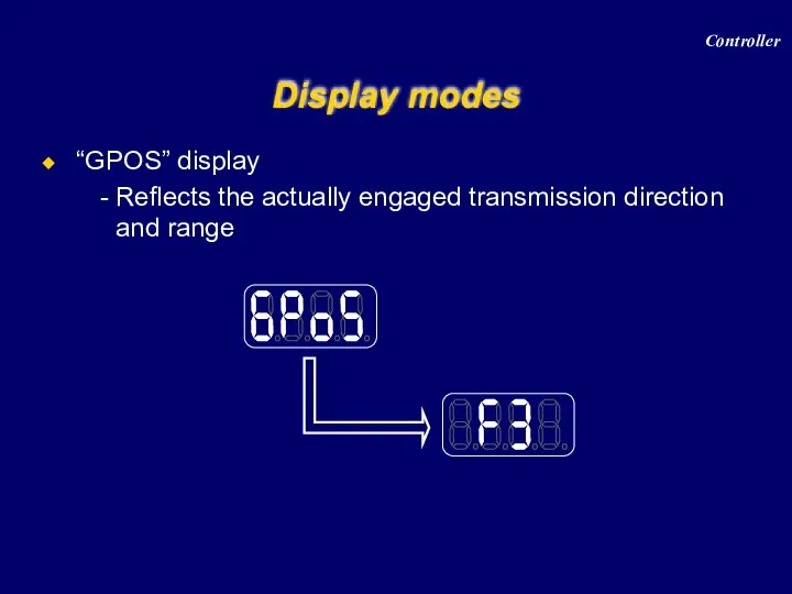
“GPOS” display
Reflects the actually engaged transmission direction and range
Display modes
Controller
“GPOS” display
Reflects the actually engaged transmission direction and range
Display modes
Controller
Display modes
“VSPD” display
Shows the vehicle speed in km/h or MPH,
Display modes
“VSPD” display
Shows the vehicle speed in km/h or MPH,
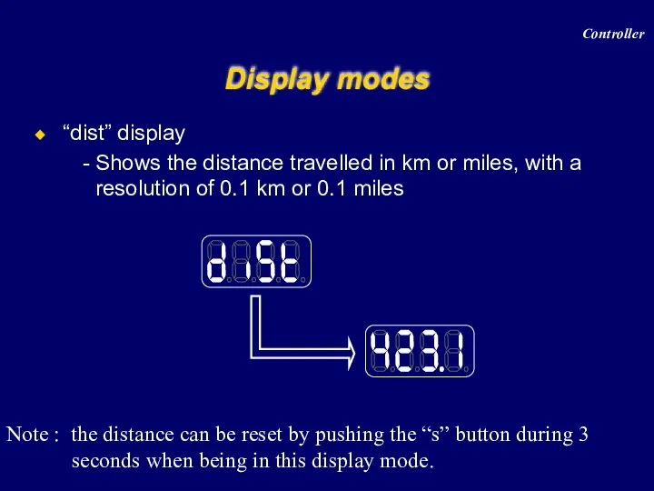
“dist” display
Shows the distance travelled in km or miles, with
“dist” display
Shows the distance travelled in km or miles, with

Display modes
Controller
Display modes
Controller
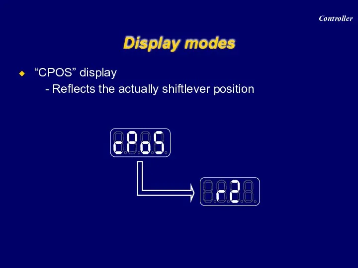
“CPOS” display
Reflects the actually shiftlever position
Display modes
Controller
“CPOS” display
Reflects the actually shiftlever position
Display modes
Controller
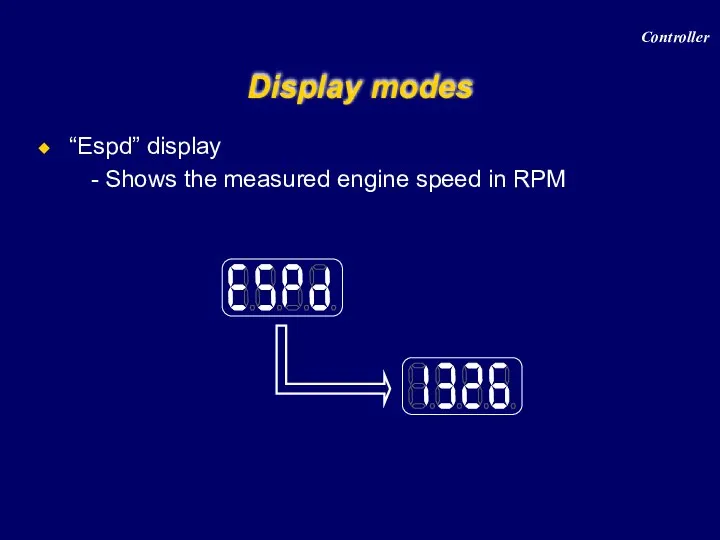
“Espd” display
Shows the measured engine speed in RPM
Display modes
Controller
“Espd” display
Shows the measured engine speed in RPM
Display modes
Controller
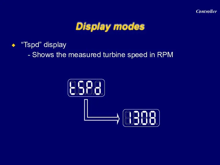
“Tspd” display
Shows the measured turbine speed in RPM
Display modes
Controller
“Tspd” display
Shows the measured turbine speed in RPM
Display modes
Controller
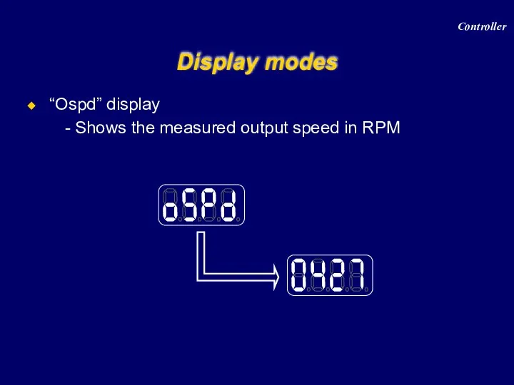
“Ospd” display
Shows the measured output speed in RPM
Display modes
Controller
“Ospd” display
Shows the measured output speed in RPM
Display modes
Controller
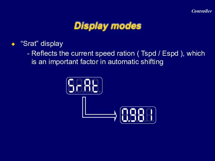
“Srat” display
Reflects the current speed ration ( Tspd / Espd
“Srat” display
Reflects the current speed ration ( Tspd / Espd
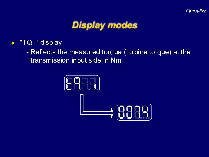
“TQ I” display
Reflects the measured torque (turbine torque) at the
“TQ I” display
Reflects the measured torque (turbine torque) at the
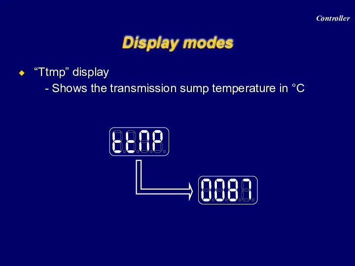
“Ttmp” display
Shows the transmission sump temperature in °C
Display modes
Controller
“Ttmp” display
Shows the transmission sump temperature in °C
Display modes
Controller
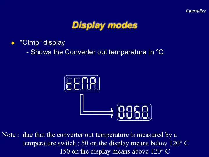
“Ctmp” display
Shows the Converter out temperature in °C
Display modes
Note :
“Ctmp” display
Shows the Converter out temperature in °C
Display modes
Note :

Display modes
Controller
Display modes
Controller
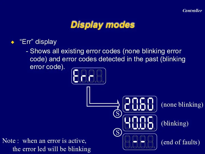
“Err” display
Shows all existing error codes (none blinking error code)
“Err” display
Shows all existing error codes (none blinking error code)
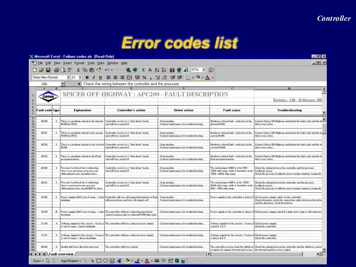
Error codes list
Controller
Error codes list
Controller
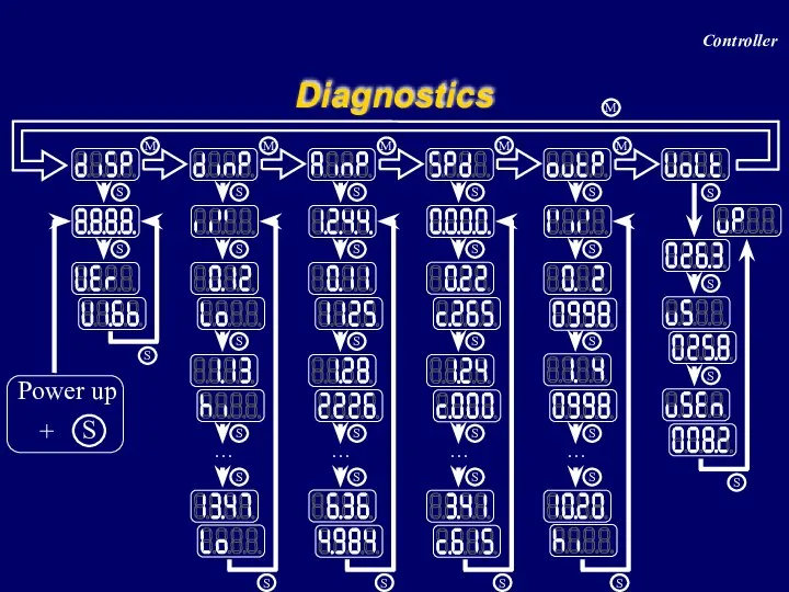
Diagnostics
Controller
Diagnostics
Controller
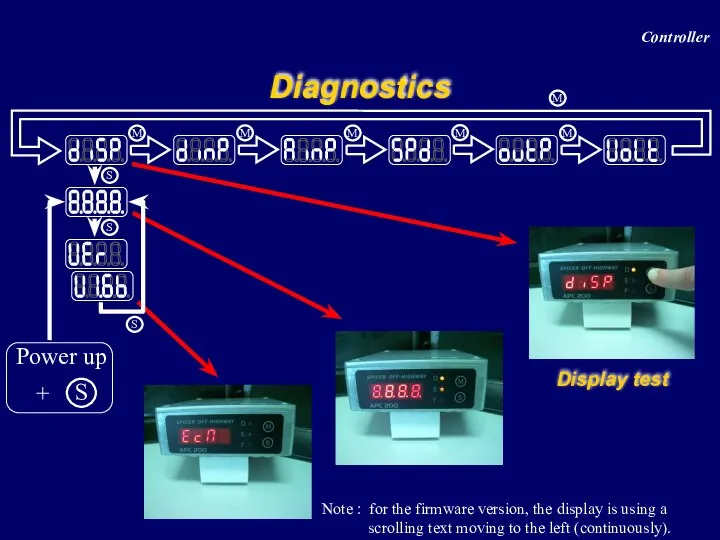
Diagnostics
Note : for the firmware version, the display is using a
Diagnostics
Note : for the firmware version, the display is using a
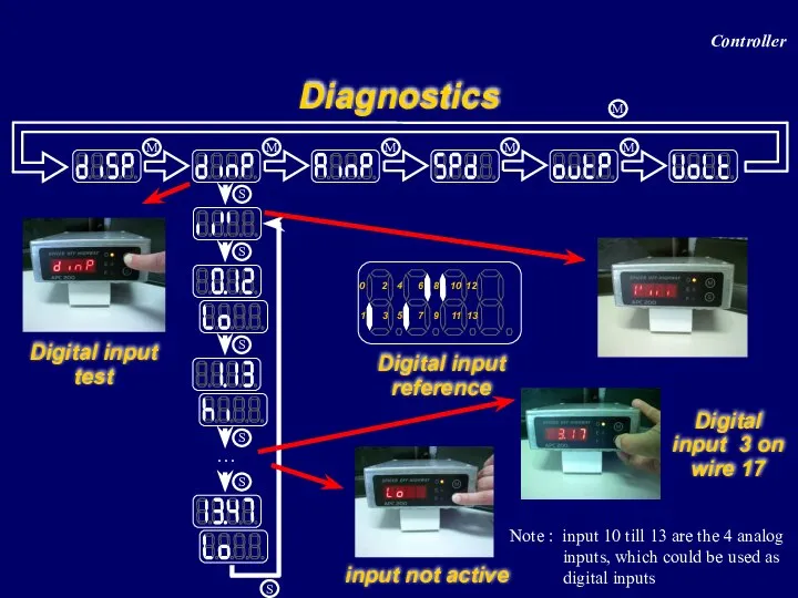
Diagnostics
Digital input test
Digital input reference
0
1
2
3
4
5
8
9
6
7
10
11
12
13
Note : input 10 till 13 are
Diagnostics
Digital input test
Digital input reference
0
1
2
3
4
5
8
9
6
7
10
11
12
13
Note : input 10 till 13 are
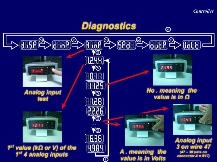
Diagnostics
Analog input test
1st value (kΩ or V) of the 1st 4
Diagnostics
Analog input test
1st value (kΩ or V) of the 1st 4
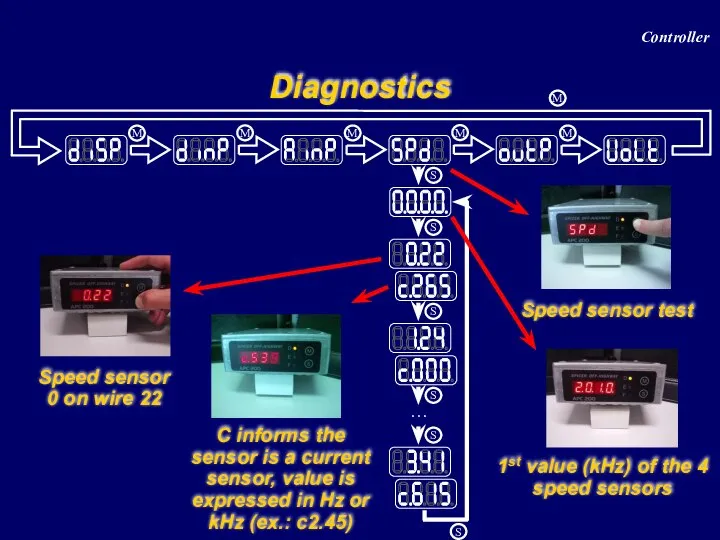
Diagnostics
Speed sensor test
C informs the sensor is a current sensor, value
Diagnostics
Speed sensor test
C informs the sensor is a current sensor, value
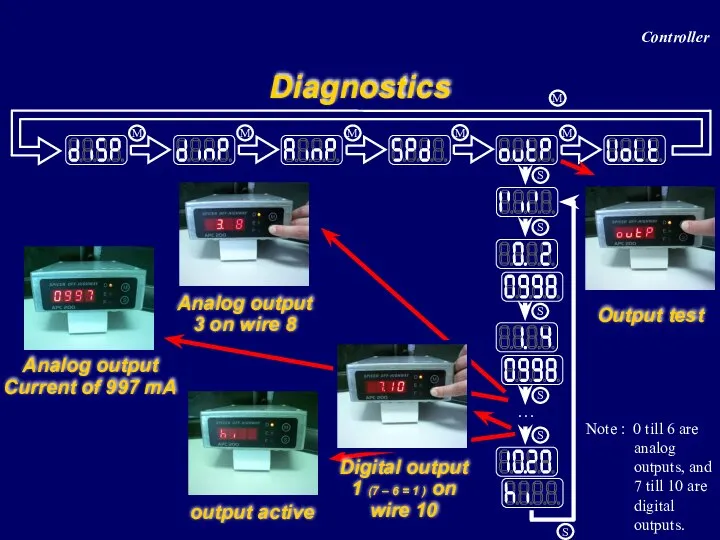
Diagnostics
Output test
Analog output
Current of 997 mA
Analog output 3 on wire
Diagnostics
Output test
Analog output
Current of 997 mA
Analog output 3 on wire
Diagnostics
Voltage test
Voltage switched power
Voltage sensor power supply
22.7 volt
8.1 volt
Controller
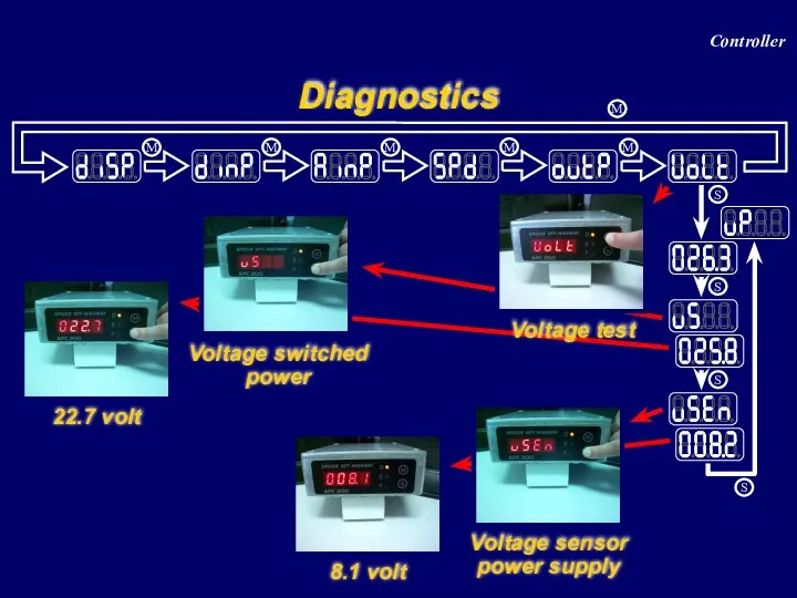
Diagnostics
Voltage test
Voltage switched power
Voltage sensor power supply
22.7 volt
8.1 volt
Controller
Calibration APC200-Transmission
Menu structure overview
Transmission calibration (clutch filling)
Heat mode
Calibration of the
Calibration APC200-Transmission
Menu structure overview
Transmission calibration (clutch filling)
Heat mode
Calibration of the
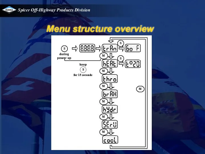
Menu structure overview
Menu structure overview
Transmission calibration (clutch filling)
Introduction
What?
Is determining volume of oil that is needed
Transmission calibration (clutch filling)
Introduction
What?
Is determining volume of oil that is needed
Transmission calibration (clutch filling)
Introduction
How ?
Direction (FWD/REV)clutches are calibrated by fully activating
Transmission calibration (clutch filling)
Introduction
How ?
Direction (FWD/REV)clutches are calibrated by fully activating
Transmission calibration (clutch filling)
Introduction
A transmission calibration has to be performed :
when
Transmission calibration (clutch filling)
Introduction
A transmission calibration has to be performed :
when
Transmission calibration (clutch filling)
How ? (1/3)
Enter the calibration menu by pressing
Transmission calibration (clutch filling)
How ? (1/3)
Enter the calibration menu by pressing
Transmission calibration (clutch filling)
How ? (2/3)
If all these conditions are met,
Transmission calibration (clutch filling)
How ? (2/3)
If all these conditions are met,
Transmission calibration (clutch filling)
How ? (3/3)
When all clutches have been calibrated,
Transmission calibration (clutch filling)
How ? (3/3)
When all clutches have been calibrated,
Heat mode (1/3)
Goal : warm up transmission in a fast way
Heat mode (1/3)
Goal : warm up transmission in a fast way
Heat mode (2/3)
Perform the following scheme to warm up the transmission
Heat mode (2/3)
Perform the following scheme to warm up the transmission
Heat mode (3/3)
Note : When the converter out temperature would exceed
Heat mode (3/3)
Note : When the converter out temperature would exceed
Other messages during calibration (1/5)
1. Calibration condition messages
Other messages during calibration (1/5)
1. Calibration condition messages
Other messages during calibration (2/5)
1. Calibration condition messages (part 2)
Other messages during calibration (2/5)
1. Calibration condition messages (part 2)
Other messages during calibration (3/5)
2. Calibration error messages
E1.25 : during calibration,
Other messages during calibration (3/5)
2. Calibration error messages
E1.25 : during calibration,
Other messages during calibration (4/5)
2. Calibration error messages continued
E1.10 : during
Other messages during calibration (4/5)
2. Calibration error messages continued
E1.10 : during
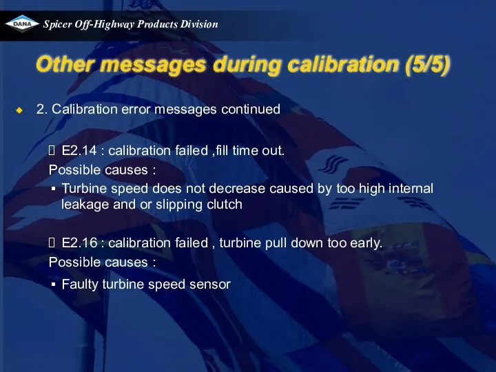
Other messages during calibration (5/5)
2. Calibration error messages continued
E2.14 : calibration
Other messages during calibration (5/5)
2. Calibration error messages continued
E2.14 : calibration
Calibration of analogue imputs
Example : brake pedal (1/4)
Enter the calibration menu
Calibration of analogue imputs
Example : brake pedal (1/4)
Enter the calibration menu
Calibration of analogue imputs
Example : brake pedal (2/4)
Then, the APC asks
Calibration of analogue imputs
Example : brake pedal (2/4)
Then, the APC asks
Calibration of analogue imputs
Example : brake pedal (3/4)
Finally, the APC asks
Calibration of analogue imputs
Example : brake pedal (3/4)
Finally, the APC asks
Calibration of analogue imputs
Example : brake pedal (4/4)
Calibration of analogue imputs
Example : brake pedal (4/4)
TE transmission field experience
TE13/17 field campaign
Speed sensor changes
Case studies
TE transmission field experience
TE13/17 field campaign
Speed sensor changes
Case studies
TE transmission field experience
TE13/17 field campaign
Clutch end plate snapring jumps out
TE transmission field experience
TE13/17 field campaign
Clutch end plate snapring jumps out
TE transmission field experience
Speed sensor changes.
Cracked speedsensor housing causes potting material
TE transmission field experience
Speed sensor changes.
Cracked speedsensor housing causes potting material
TE transmission field experience
Case studies
1. Vehicle stops error 00.50
action 1
TE transmission field experience
Case studies
1. Vehicle stops error 00.50
action 1
TE transmission field experience
Case studies
2. Vehicle has a delay when downshifting,
TE transmission field experience
Case studies
2. Vehicle has a delay when downshifting,
TE transmission field experience
Case studies
3. Tel call : machine sometimes shows
TE transmission field experience
Case studies
3. Tel call : machine sometimes shows
TE transmission field experience
Case studies
4. Tel call : unit shocks when
TE transmission field experience
Case studies
4. Tel call : unit shocks when
TE transmission field experience
Case studies
5. Tel call : failure code 20/61
TE transmission field experience
Case studies
5. Tel call : failure code 20/61
TE transmission field experience
Case studies
6. Tel call : error code 42/04
TE transmission field experience
Case studies
6. Tel call : error code 42/04
 МКТ и термодинамика
 Бүкіл әлемдік тартылыс күші
 Магнітне поле
 Момент силы относительно центра (точки)
 Основы радиационной дозиметрии
  Электромагнитные волны
 Блоки. Золотое правило механики
 Перспективы использования наномолекулярных материалов в строительстве
 Барометрическая формула. Распределение Больцмана
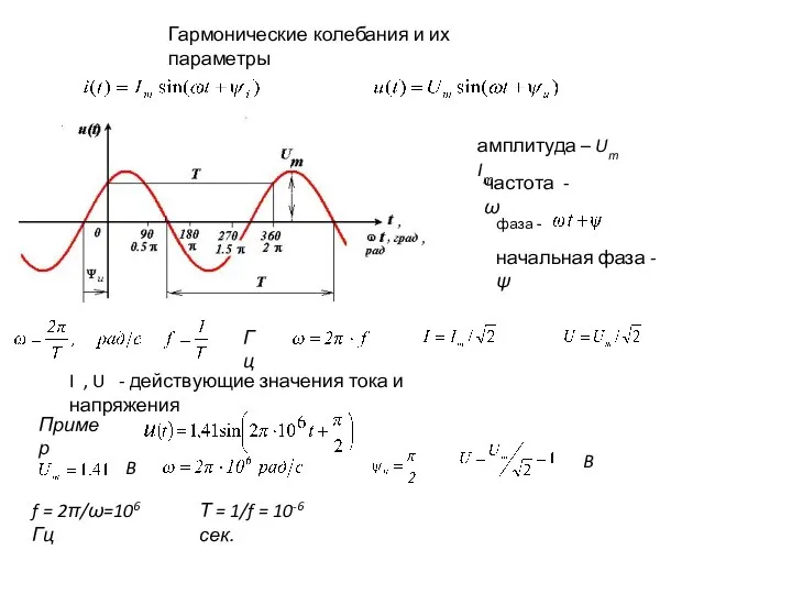 Гармонические колебания и их параметры
 Интерференция света
 Презентация по физике Транспорт будущего
 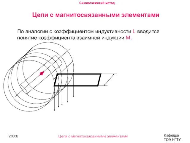 Символический метод. Цепи с магнитосвязанными элементами
 Презентация на тему: «Теория фотоэффекта»
 Процессы переноса
 Ультразвук и инфразвук
 Биоэлектрлік құбылыстар. Биопотенциалдар табиғаты туралы қазіргі кездегі көзқарас
 Презентация Голография
  Зависимость силы тока от напряжения. Сопротивление проводника
 Кинематика материальной точки. (Тема 1)
 Диагностика и ремонт ТНВД двигателя автомобиля Киа Рио в автосервисе ООО КАРС
 Энергия мысли. Сила мысли
 Тайна сокровищ Ощущение тайны - наиболее прекрасное из доступных нам переживаний. Именно это чувство стоит у колыбели настоящ
 Основні закономірності термодинаміки. Термостатика та термодинаміка. Лекція 1
 Единая физическая картина мира. 11 класс
 Электротехнические материалы
 Анализ сигналов
 Аттестационная работа. Образовательная программа элективного курса. Математические методы в физике