- AT - A4AF3. Automatic Transaxle

Содержание
- 2. Appreance AT - A4AF3
- 3. ③ : Project name A : Alpha B : Beta ① : Type A : Automatic
- 4. Location of PCM AT - A4AF3
- 5. Specification AT - A4AF3
- 6. Transaxle layout AT - A4AF3
- 7. Note : ● - Element engaged in each gear position F/C: Front Clutch R/C: Rear Clutch
- 8. Short pinion Long pinion Ring gear (Annulus gear) Forward sun gear Reverse sun gear End clutch
- 9. 1st Gear (“D” and “2” range) Operating elements : * Rear clutch * One-way clutch Forward
- 10. 1st Gear (“L” range) Operating elements : * Rear clutch * Low-reverse brake Short pinion Carrier
- 11. 2nd Gear (“D” and “2” range) Operating elements : * Rear clutch * Kickdown brake Short
- 12. 3rd Gear (“D” range) Operating elements : * Front clutch * Rear clutch * End clutch
- 13. Does end clutch deliver power ? ? No, end clutch is powered for preparing 4th gear
- 14. 4th Gear (“D” range) Operating elements : * Kickdown brake * End clutch Kickdown brake End
- 15. Reverse range Operating elements : * Front clutch * Low-reverse brake Low-reverse brake Front clutch Reverse
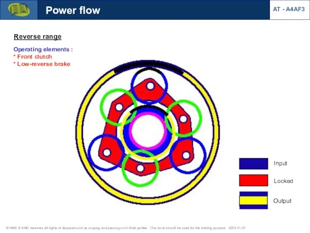
- 16. AT - A4AF3 Power flow Reverse range Operating elements : * Front clutch * Low-reverse brake
- 17. #1 #2 #13 #12 #11 #10 #3 #4 #5 #6 #7 #8 #9 Fiber Fiber Thrust
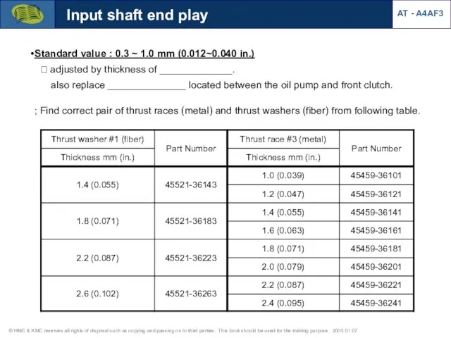
- 18. Input shaft end play Standard value : 0.3 ~ 1.0 mm (0.012~0.040 in.) ? adjusted by
- 19. Measure the input shaft endplay and select a proper #3 thrust race and #1 thrust washer.
- 20. #3 thrust race selection ? Equation : (Measurement - Standard endplay) + Thickness of old part
- 21. Front clutch Engaged at D3, R range Operates reverse sun gear End play : 0.4 ~
- 22. Input shaft Rear clutch retainer Rear clutch Engaged at D1,2,3 Operates forward sun gear End play
- 23. End clutch Engaged at D3,4 (powered only at D4) Operates planetary carrier End play : 0.4
- 24. Kick-down drum Kick-down band Piston rod & piston Kick down brake Engaged at D2,4 hold reverse
- 25. Kick down brake Kickndown brake servo piston Servo Release Pressure Servo Apply Pressure K/D switch contact
- 26. ? Service Point Symptom - Shift shock at 1st ? 2nd gear DTC: None Cause: Kickdown
- 27. ① Loosen the adjust screw lock nut Kick down brake adjustment ② Tighten and loosen the
- 28. ③ Tighten the adjust screw (Torque : 5Nm, 50kgcm) Torque ④ Mark the starting point and
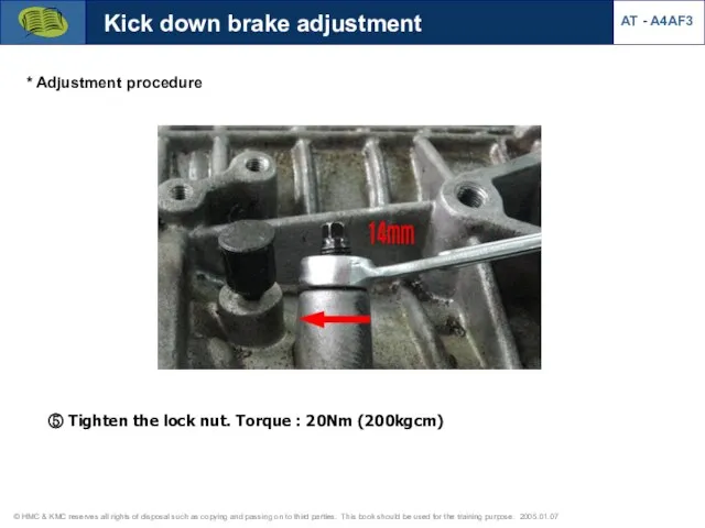
- 29. Kick down brake adjustment AT - A4AF3 * Adjustment procedure ⑤ Tighten the lock nut. Torque
- 30. Low & Reverse brake Engaged at L, R range holds planetary carrier End play : 0.675
- 31. Service Point “N”→”R” shift (C1,B2) t(sec) B2 actuation point moved C1 actuation point (delayed proper endplay)
- 32. Free Lock Outer race (planetary gear carrier) Inner race (Center support) Sprag Annulus gear Short pinion
- 33. Pressure check point Reducing pressure Damper Release Damper Apply Rear clutch Front clutch AT - A4AF3
- 34. * Function 1) To reduce the shift shock when shifting from N→D, D→N. 2) To prevent
- 35. Outputs Inputs SCSV-A,B,C (ON/OFF) PCSV-A,B (PWM) DCCSV (PWM) Input speed sensor (PG-A) Output speed sensor (PG-B)
- 36. Input speed sensor (PG-A) PG-A detects _________________ speed. Sensor resistance : 215~275Ω (20˚C) Input speed sensor
- 37. Output speed sensor (PG-B) Output speed sensor (PG-B) PG-B detects __________________ speed. Sensor resistance : 215~275Ω
- 38. Output waveform 2.5V 2.5V Input speed sensor AT - A4AF3 * Output voltage at IG on
- 39. Diagnosis (input speed sensor) AT - A4AF3 * Rationality
- 40. * Input speed sensor open Diagnosis (input speed sensor) AT - A4AF3
- 41. Diagnosis (output speed sensor) AT - A4AF3 * Output speed sensor open
- 42. * Gear ratio (1st gear speed) Failsafe (incorrect gear ratio) AT - A4AF3
- 43. * Gear ratio (2nd ~ 4th gear speed) Failsafe (incorrect gear ratio) AT - A4AF3
- 44. Kick-down switch AT - A4AF3
- 45. Diagnosis (K/D switch) * K/D switch open or short to GND (No MIL) AT - A4AF3
- 46. Brake switch AT - A4AF3 [Brake switch signal] Brake applied High :12V Low : 0V Purpose
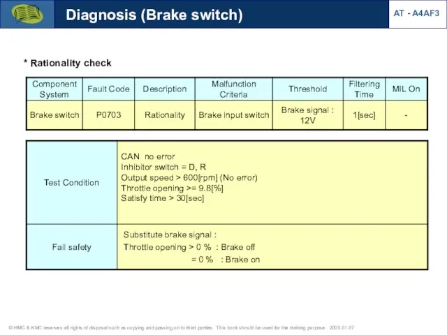
- 47. Diagnosis (Brake switch) AT - A4AF3 * Rationality check
- 48. Oil temperature sensor [Valve body] Oil temperature sensor Pressure control : PCSV duty changes according to
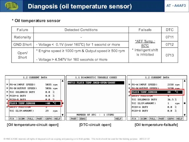
- 49. Diangosis (oil temperature sensor) * Oil temperature sensor AT - A4AF3 [Oil temperature-circuit open] [DTC-circuit open]
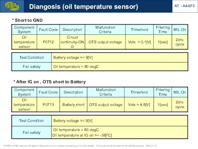
- 50. Diangosis (oil temperature sensor) AT - A4AF3 * Short to GND * After IG on ,
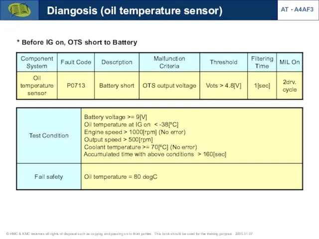
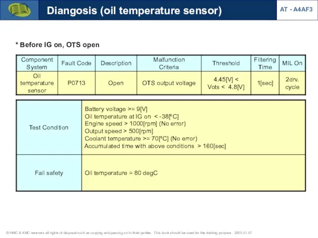
- 51. Diangosis (oil temperature sensor) AT - A4AF3 * Before IG on, OTS short to Battery
- 52. Diangosis (oil temperature sensor) AT - A4AF3 * After IG on, OTS open
- 53. Diangosis (oil temperature sensor) AT - A4AF3 * Before IG on, OTS open
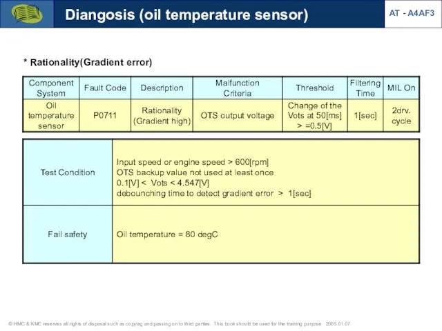
- 54. Diangosis (oil temperature sensor) AT - A4AF3 * Rationality(Gradient error)
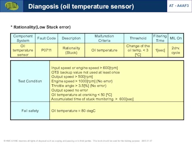
- 55. Diangosis (oil temperature sensor) AT - A4AF3 * Rationality(Low Stuck error)
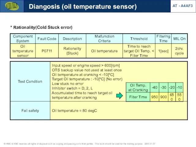
- 56. Diangosis (oil temperature sensor) AT - A4AF3 * Rationality(Cold Stuck error)
- 57. * Rationality(High Stuck error) Diangosis (oil temperature sensor) AT - A4AF3
- 58. Dashboard range signal AT - A4AF3 Cluster Inhibitor switch P R N D PCM 2 L
- 59. Inhibitor switch (TR range sw) * Shift pattern at each range - D (O/D ON) :
- 60. * Rationality(Multiple signal) Diagnosis (Inhibitor switch) AT - A4AF3
- 61. * Inhibitor switch open Diagnosis (Inhibitor switch) AT - A4AF3
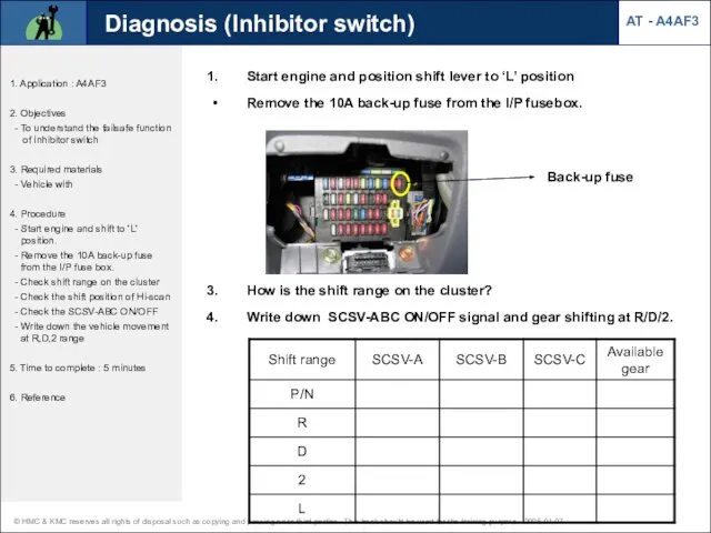
- 62. AT - A4AF3 Diagnosis (Inhibitor switch) 1. Application : A4AF3 2. Objectives - To understand the
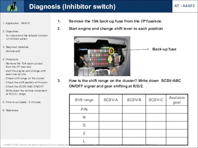
- 63. AT - A4AF3 Diagnosis (Inhibitor switch) 1. Application : A4AF3 2. Objectives - To understand the
- 64. AT - A4AF3 Diagnosis (Inhibitor switch) 1. Application : A4AF3 2. Objectives - To understand the
- 65. AT - A4AF3 Diagnosis (Inhibitor switch) 1. Application : A4AF3 2. Objectives - To understand the
- 66. AT - A4AF3 Diagnosis (Inhibitor switch) 1. Application : A4AF3 2. Objectives - To understand the
- 67. AT - A4AF3 Diagnosis (Inhibitor switch) 1. Application : A4AF3 2. Objectives - To understand the
- 68. 1. Type - On/Off control : - PWM control (35Hz) : 2. Control elements - PCSV-A
- 69. Solenoid valves Operation table at D range (SCSV-A,B,C) Solenoid resistance - PCSV: 2.9±0.3Ω - SCSV: 22.3±1.5Ω
- 70. Solenoid valves Current data (Damper clutch control solenoid valve) D1 D2 D3 D4 Damper clutch operation
- 71. Solenoid valves Current data (Pressure control solenoid valve) N-D D1 D1 N-D D1 D2 D3 D4
- 72. Solenoid valves Current data (Shift control solenoid valve) SCSV-A, operation at D range SCSV-B, operation at
- 73. Solenoid valves Circuit diagram [DCCSV duty signal] [PCSV-A duty signal-duty 100%] AT - A4AF3
- 74. Diagnosis (solenoid valves) [Failsafe: 3rd gear hold at D,2,L] AT - A4AF3
- 75. Diagnosis (damper clutch control) AT - A4AF3 * Rationality(Closed stuck)
- 76. Diagnosis (damper clutch control) AT - A4AF3 * Rationality(Open stuck)
- 77. Diagnosis (CAN BUS OFF Error) AT - A4AF3 * CAN BUS OFF
- 78. Diagnosis (CAN BUS OFF Error) AT - A4AF3 CAN BUS OFF Error dection 1) CAN-Low short
- 79. 1. Verify complaint 3. Problem symptom confirmation 4. 1) Are there DTC ? 2) Are current
- 80. 6. Electrical problem 7. Electrical 8. Hydraulic problem 9. Mechanical 10. Hydraulic DTC chart, circuit &
- 81. Symptom analysis AT - A4AF3
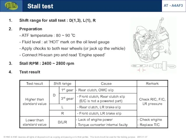
- 82. AT - A4AF3 Stall test Shift range for stall test : D(1,3), L(1), R Preparation -
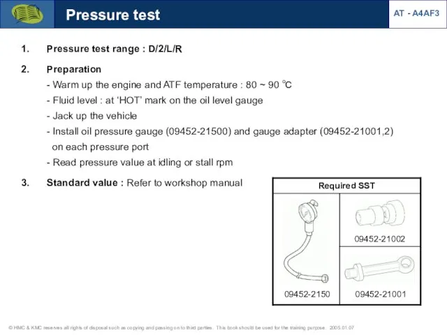
- 83. Pressure test Pressure test range : D/2/L/R Preparation - Warm up the engine and ATF temperature
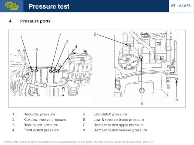
- 84. Pressure test Pressure ports AT - A4AF3 Reducing pressure Kickdown wervo pressure Rear clutch pressure Front
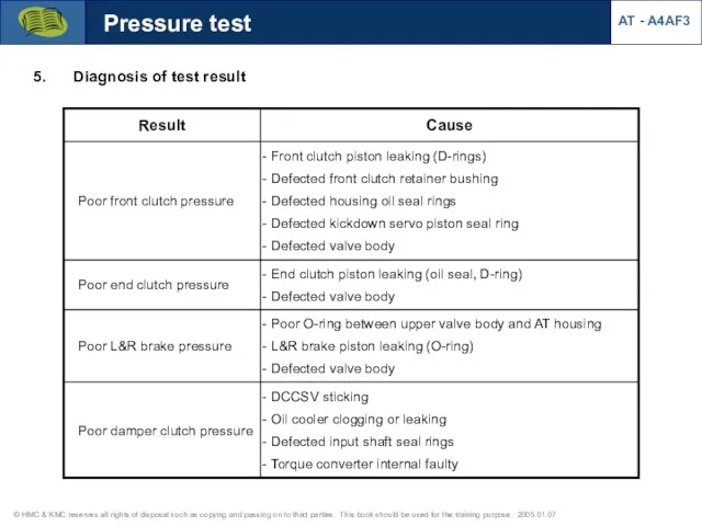
- 85. Pressure test Diagnosis of test result AT - A4AF3
- 86. AT Tester with adapter cables for AT (F4A**, F4EL-K, AISIN) Pressure test (Preparation) AT - A4AF3
- 87. Pressure sensor installation with AT Tester AT - A4AF3 [AT Tester] [Pressure control box] [Pressure sensor
- 88. Pressure test (Preparation) Pressure sensor installation with AT Tester AT - A4AF3
- 89. [R/C pressure & PCSV-B operation at N?D?N] Pressure test 1) Rear clutch pressure Rear clutch pressure
- 90. AT - A4AF3 Pressure test 1) Rear clutch pressure N?D?2 L range, idle [R/C pressure at
- 91. Pressure test Damper clutch pressure (Waveform from pressure sensor) [At P,N range] [At R range] D/R
- 92. Damper clutch pressure Pressure test [At D range] Damper clutch pressure (Waveform from pressure sensor) D/R
- 93. Pressure test [At 2 range] [At L range] Damper clutch pressure (Waveform from pressure sensor) D/R
- 94. Pressure test Kick down servo apply pressure (Waveform from pressure sensor) [At N-D control] D range
- 95. Kick down servo apply pressure (Waveform from pressure sensor) Pressure test 2-2 (Servo apply pressure) 8.5
- 96. L&R brake pressure (Waveform from pressure sensor) Pressure test [At R range] N?R [At L range]
- 98. Скачать презентацию
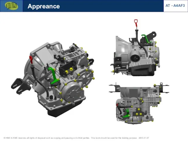
Appreance
AT - A4AF3
Appreance
AT - A4AF3
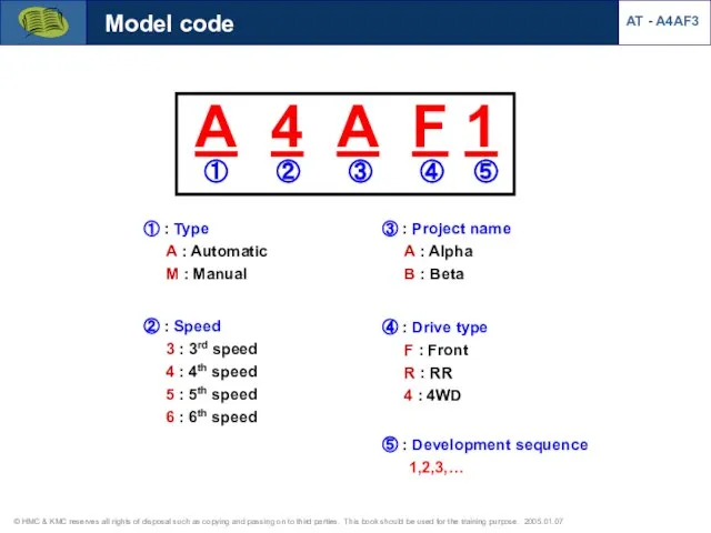
③ : Project name
A : Alpha
B : Beta
① :
③ : Project name
A : Alpha
B : Beta
① :
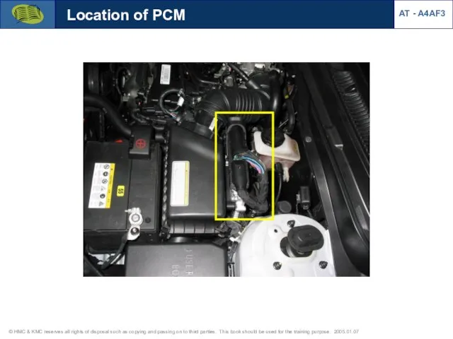
Location of PCM
AT - A4AF3
Location of PCM
AT - A4AF3
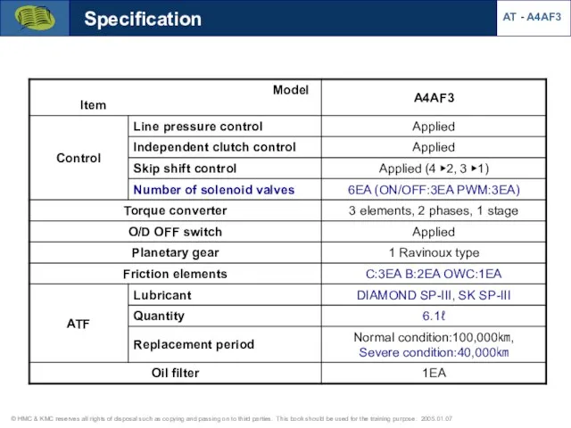
Specification
AT - A4AF3
Specification
AT - A4AF3
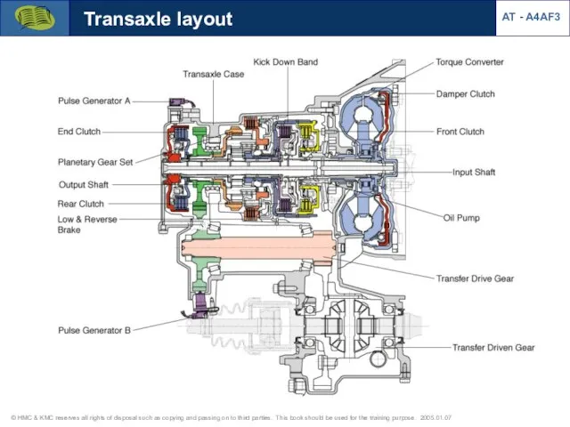
Transaxle layout
AT - A4AF3
Transaxle layout
AT - A4AF3
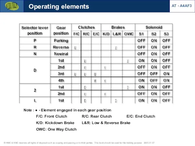
Note : ● - Element engaged in each gear position
F/C:
Note : ● - Element engaged in each gear position F/C:
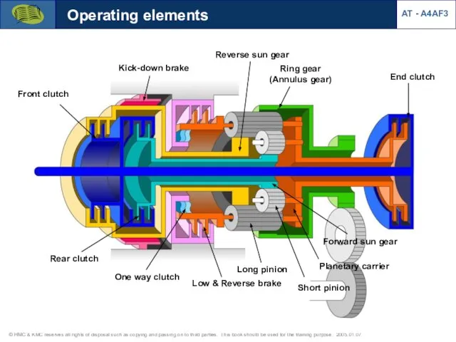
Short pinion
Long pinion
Ring gear
(Annulus gear)
Forward sun gear
Reverse sun gear
End clutch
Front clutch
Rear
Short pinion
Long pinion
Ring gear
(Annulus gear)
Forward sun gear
Reverse sun gear
End clutch
Front clutch
Rear
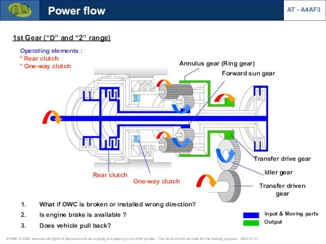
1st Gear (“D” and “2” range)
Operating elements :
* Rear clutch
* One-way
1st Gear (“D” and “2” range)
Operating elements :
* Rear clutch
* One-way
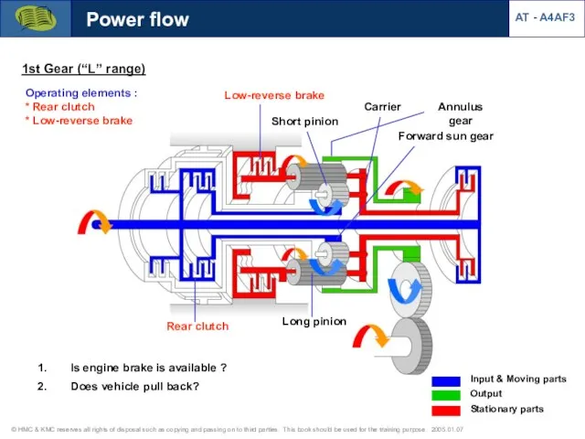
1st Gear (“L” range)
Operating elements :
* Rear clutch
* Low-reverse brake
Short pinion
Carrier
Forward
1st Gear (“L” range)
Operating elements :
* Rear clutch
* Low-reverse brake
Short pinion
Carrier
Forward
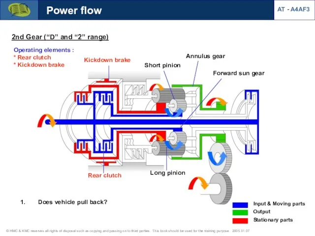
2nd Gear (“D” and “2” range)
Operating elements :
* Rear clutch
* Kickdown
2nd Gear (“D” and “2” range)
Operating elements :
* Rear clutch
* Kickdown
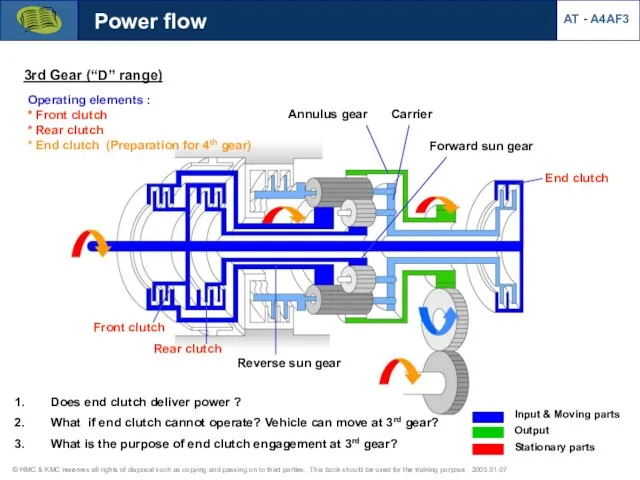
3rd Gear (“D” range)
Operating elements :
* Front clutch
* Rear clutch
* End
3rd Gear (“D” range)
Operating elements :
* Front clutch
* Rear clutch
* End
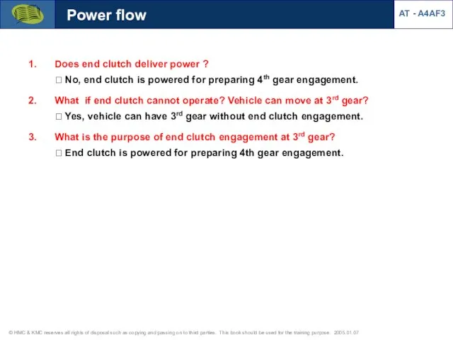
Does end clutch deliver power ?
? No, end clutch is powered
Does end clutch deliver power ? ? No, end clutch is powered
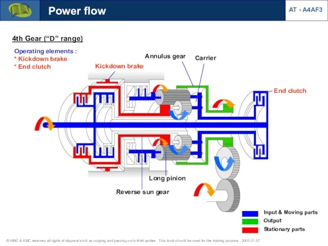
4th Gear (“D” range)
Operating elements :
* Kickdown brake
* End clutch
Kickdown brake
End
4th Gear (“D” range)
Operating elements :
* Kickdown brake
* End clutch
Kickdown brake
End
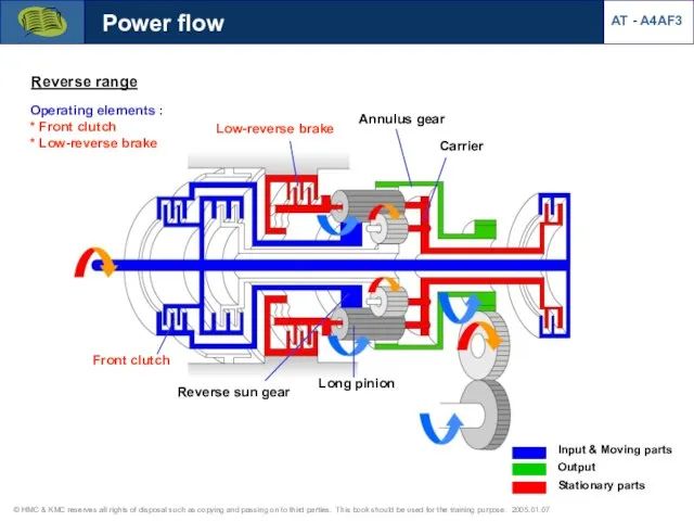
Reverse range
Operating elements :
* Front clutch
* Low-reverse brake
Low-reverse brake
Front clutch
Reverse sun
Reverse range
Operating elements :
* Front clutch
* Low-reverse brake
Low-reverse brake
Front clutch
Reverse sun
AT - A4AF3
Power flow
Reverse range
Operating elements :
* Front clutch
* Low-reverse brake
Input
Locked
Output
AT - A4AF3
Power flow
Reverse range
Operating elements :
* Front clutch
* Low-reverse brake
Input
Locked
Output
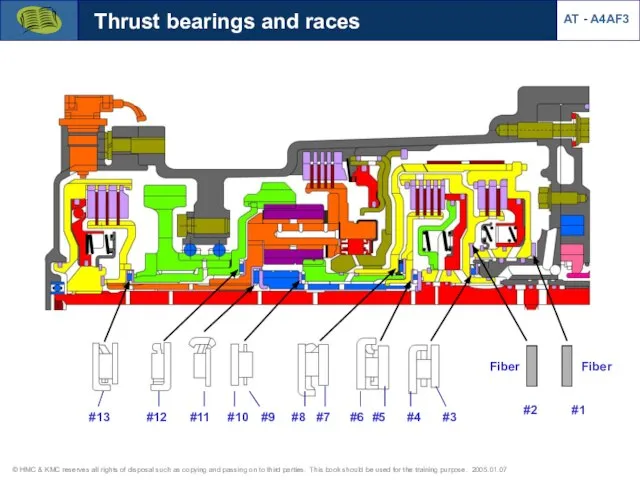
#1
#2
#13
#12
#11
#10
#3
#4
#5
#6
#7
#8
#9
Fiber
Fiber
Thrust bearings and races
AT - A4AF3
#1
#2
#13
#12
#11
#10
#3
#4
#5
#6
#7
#8
#9
Fiber
Fiber
Thrust bearings and races
AT - A4AF3
Input shaft end play
Standard value : 0.3 ~ 1.0 mm (0.012~0.040
Input shaft end play
Standard value : 0.3 ~ 1.0 mm (0.012~0.040
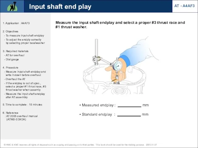
Measure the input shaft endplay and select a proper #3 thrust
Measure the input shaft endplay and select a proper #3 thrust
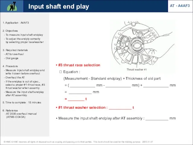
#3 thrust race selection ? Equation : (Measurement - Standard
#3 thrust race selection ? Equation : (Measurement - Standard
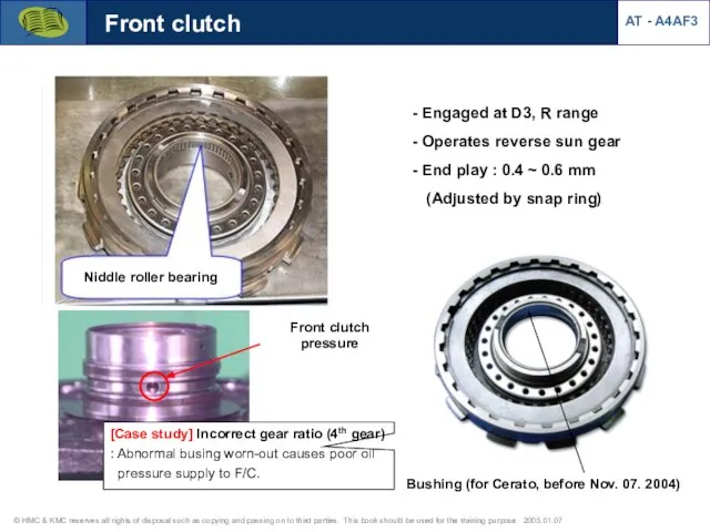
Front clutch
Engaged at D3, R range
Operates reverse sun gear
Front clutch
Engaged at D3, R range
Operates reverse sun gear
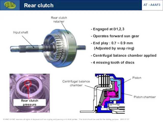
Input shaft
Rear clutch retainer
Rear clutch
Engaged at D1,2,3
Operates forward sun
Input shaft
Rear clutch retainer
Rear clutch
Engaged at D1,2,3
Operates forward sun
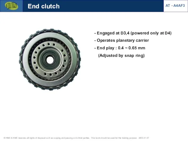
End clutch
Engaged at D3,4 (powered only at D4)
Operates planetary
End clutch
Engaged at D3,4 (powered only at D4)
Operates planetary
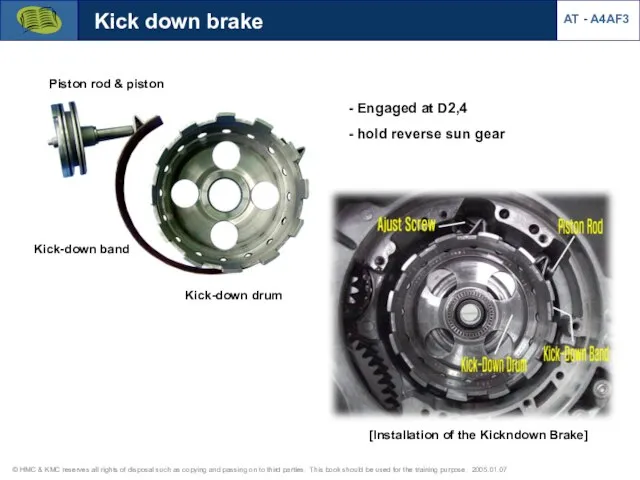
Kick-down drum
Kick-down band
Piston rod & piston
Kick down brake
Engaged at D2,4
Kick-down drum
Kick-down band
Piston rod & piston
Kick down brake
Engaged at D2,4
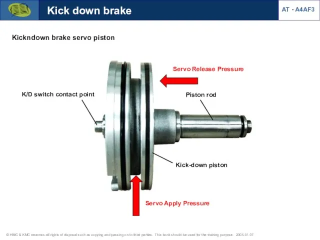
Kick down brake
Kickndown brake servo piston
Servo Release Pressure
Servo Apply Pressure
K/D switch
Kick down brake
Kickndown brake servo piston
Servo Release Pressure
Servo Apply Pressure
K/D switch
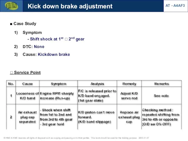
? Service Point
Symptom - Shift shock at 1st ? 2nd
? Service Point
Symptom - Shift shock at 1st ? 2nd
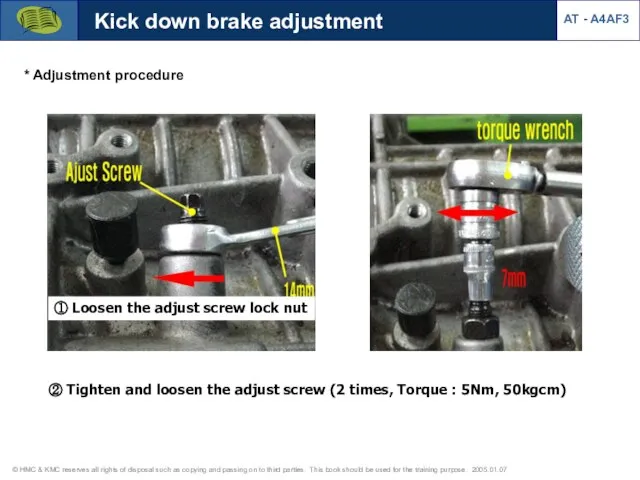
① Loosen the adjust screw lock nut
Kick down brake adjustment
② Tighten
① Loosen the adjust screw lock nut
Kick down brake adjustment
② Tighten
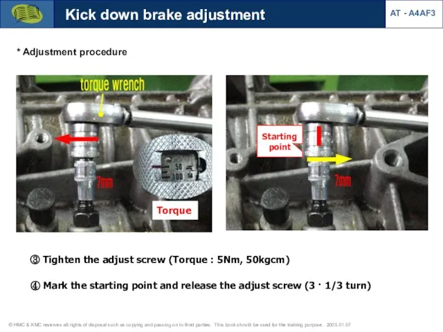
③ Tighten the adjust screw (Torque : 5Nm, 50kgcm)
Torque
④ Mark
③ Tighten the adjust screw (Torque : 5Nm, 50kgcm)
Torque
④ Mark
Kick down brake adjustment
AT - A4AF3
* Adjustment procedure
⑤ Tighten the lock
Kick down brake adjustment
AT - A4AF3
* Adjustment procedure
⑤ Tighten the lock
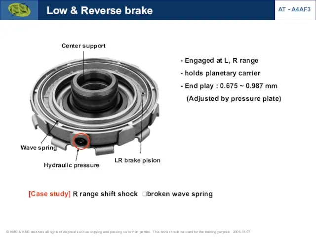
Low & Reverse brake
Engaged at L, R range
holds planetary
Low & Reverse brake
Engaged at L, R range
holds planetary
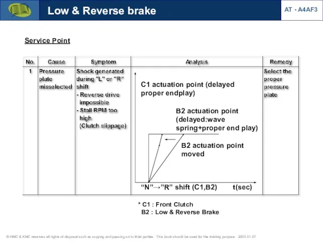
Service Point
“N”→”R” shift (C1,B2) t(sec)
B2 actuation point moved
C1 actuation point (delayed
Service Point
“N”→”R” shift (C1,B2) t(sec)
B2 actuation point moved
C1 actuation point (delayed
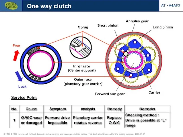
Free
Lock
Outer race
(planetary gear carrier)
Inner race
(Center support)
Sprag
Annulus gear
Short pinion
Long pinion
Forward
Free
Lock
Outer race
(planetary gear carrier)
Inner race
(Center support)
Sprag
Annulus gear
Short pinion
Long pinion
Forward
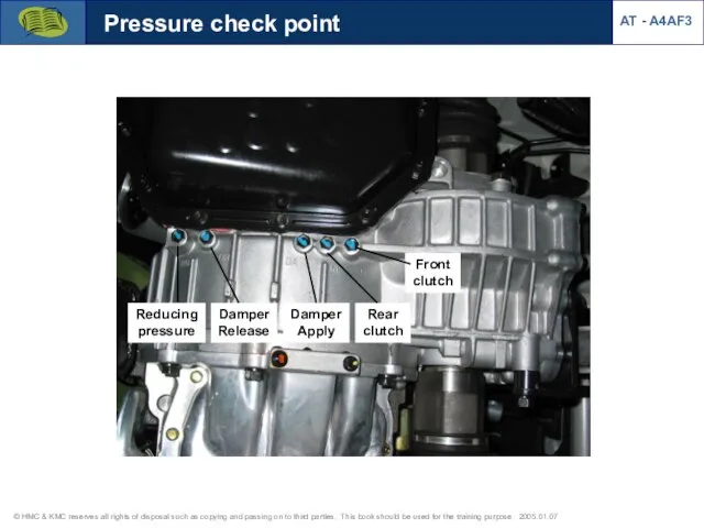
Pressure check point
Reducing pressure
Damper Release
Damper Apply
Rear clutch
Front clutch
AT - A4AF3
Pressure check point
Reducing pressure
Damper Release
Damper Apply
Rear clutch
Front clutch
AT - A4AF3
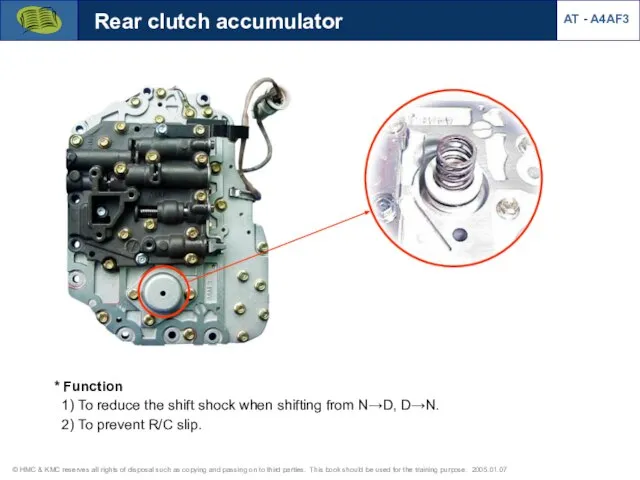
* Function
1) To reduce the shift shock when shifting from
* Function
1) To reduce the shift shock when shifting from
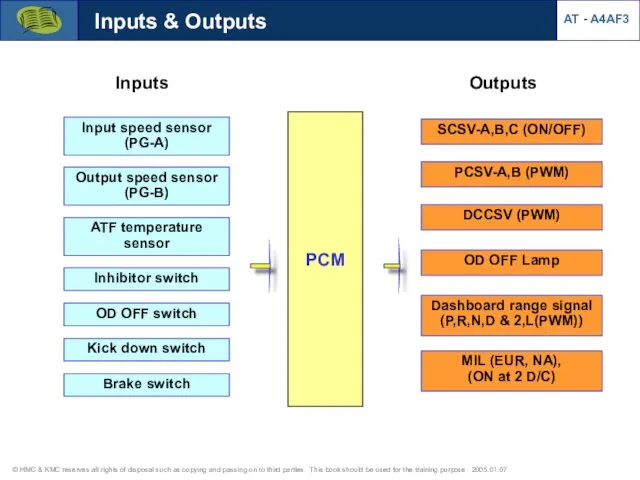
Outputs
Inputs
SCSV-A,B,C (ON/OFF)
PCSV-A,B (PWM)
DCCSV (PWM)
Input speed sensor (PG-A)
Output speed sensor
(PG-B)
ATF temperature sensor
Inhibitor
Outputs
Inputs
SCSV-A,B,C (ON/OFF)
PCSV-A,B (PWM)
DCCSV (PWM)
Input speed sensor (PG-A)
Output speed sensor
(PG-B)
ATF temperature sensor
Inhibitor
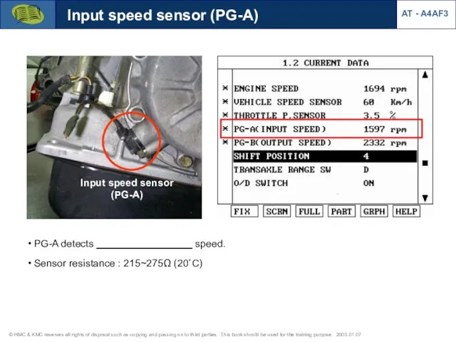
Input speed sensor (PG-A)
PG-A detects _________________ speed.
Sensor resistance :
Input speed sensor (PG-A)
PG-A detects _________________ speed.
Sensor resistance :
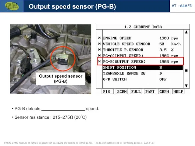
Output speed sensor (PG-B)
Output speed sensor
(PG-B)
PG-B detects __________________
Output speed sensor (PG-B)
Output speed sensor
(PG-B)
PG-B detects __________________
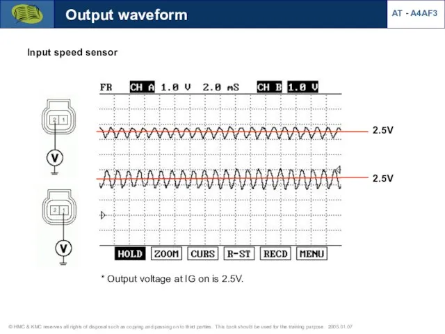
Output waveform
2.5V
2.5V
Input speed sensor
AT - A4AF3
* Output voltage at IG on
Output waveform
2.5V
2.5V
Input speed sensor
AT - A4AF3
* Output voltage at IG on
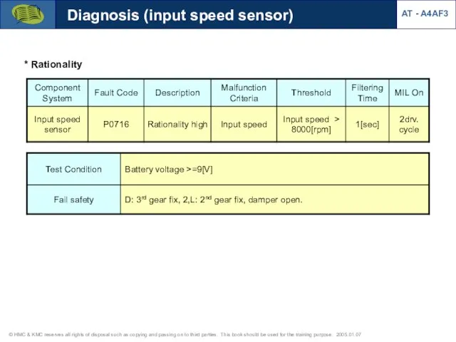
Diagnosis (input speed sensor)
AT - A4AF3
* Rationality
Diagnosis (input speed sensor)
AT - A4AF3
* Rationality
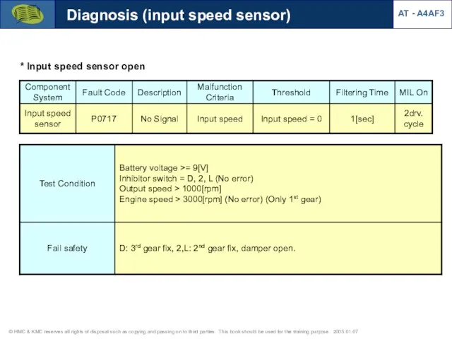
* Input speed sensor open
Diagnosis (input speed sensor)
AT - A4AF3
* Input speed sensor open
Diagnosis (input speed sensor)
AT - A4AF3
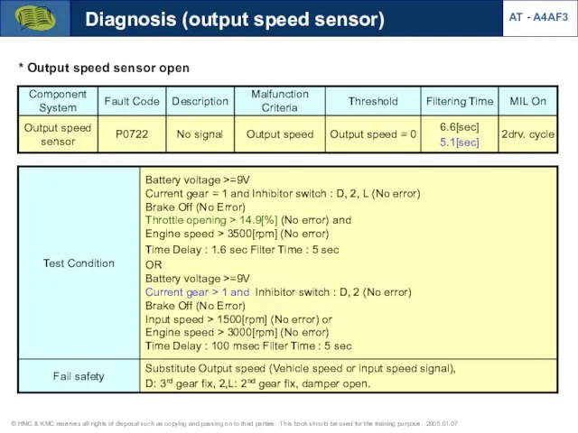
Diagnosis (output speed sensor)
AT - A4AF3
* Output speed sensor open
Diagnosis (output speed sensor)
AT - A4AF3
* Output speed sensor open
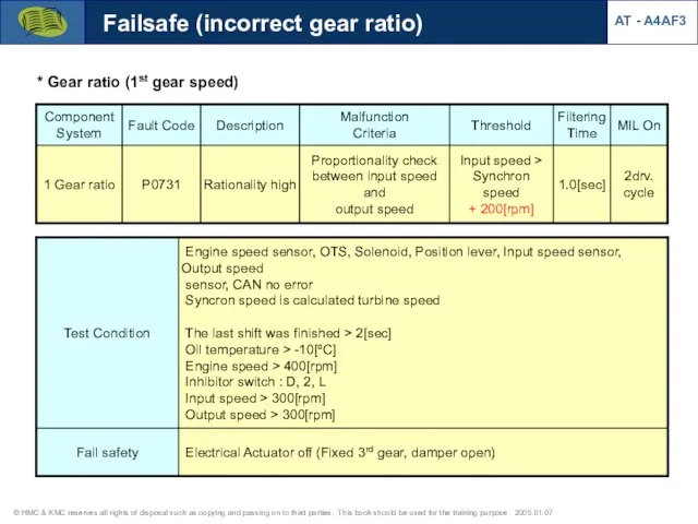
* Gear ratio (1st gear speed)
Failsafe (incorrect gear ratio)
AT - A4AF3
* Gear ratio (1st gear speed)
Failsafe (incorrect gear ratio)
AT - A4AF3
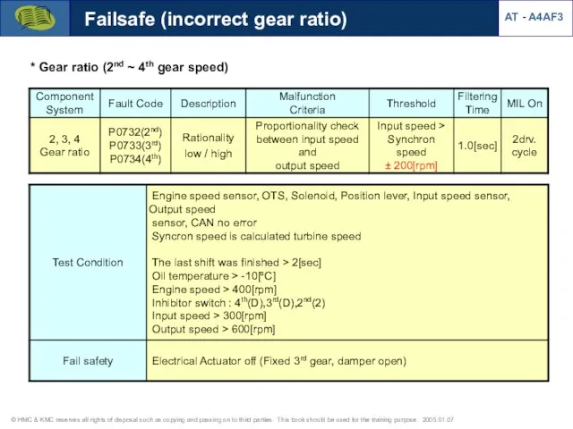
* Gear ratio (2nd ~ 4th gear speed)
Failsafe (incorrect gear ratio)
AT
* Gear ratio (2nd ~ 4th gear speed)
Failsafe (incorrect gear ratio)
AT
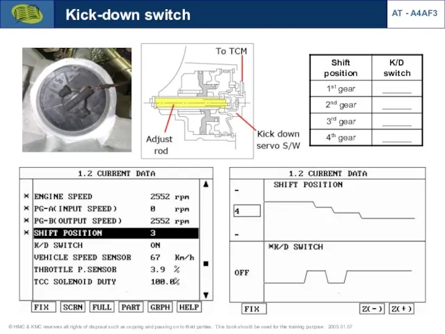
Kick-down switch
AT - A4AF3
Kick-down switch
AT - A4AF3
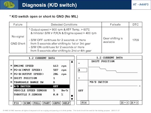
Diagnosis (K/D switch)
* K/D switch open or short to GND (No
Diagnosis (K/D switch)
* K/D switch open or short to GND (No
![Brake switch AT - A4AF3 [Brake switch signal] Brake applied High](/_ipx/f_webp&q_80&fit_contain&s_1440x1080/imagesDir/jpg/522476/slide-45.jpg)
Brake switch
AT - A4AF3
[Brake switch signal]
Brake applied
High :12V
Low : 0V
Purpose
Damper
Brake switch
AT - A4AF3
[Brake switch signal]
Brake applied
High :12V
Low : 0V
Purpose
Damper
Diagnosis (Brake switch)
AT - A4AF3
* Rationality check
Diagnosis (Brake switch)
AT - A4AF3
* Rationality check
![Oil temperature sensor [Valve body] Oil temperature sensor Pressure control :](/_ipx/f_webp&q_80&fit_contain&s_1440x1080/imagesDir/jpg/522476/slide-47.jpg)
Oil temperature sensor
[Valve body]
Oil temperature sensor
Pressure control : PCSV duty
Oil temperature sensor
[Valve body]
Oil temperature sensor
Pressure control : PCSV duty
Diangosis (oil temperature sensor)
* Oil temperature sensor
AT - A4AF3
[Oil temperature-circuit open]
[DTC-circuit
Diangosis (oil temperature sensor)
* Oil temperature sensor
AT - A4AF3
[Oil temperature-circuit open]
[DTC-circuit
Diangosis (oil temperature sensor)
AT - A4AF3
* Short to GND
* After IG
Diangosis (oil temperature sensor)
AT - A4AF3
* Short to GND
* After IG
Diangosis (oil temperature sensor)
AT - A4AF3
* Before IG on, OTS short
Diangosis (oil temperature sensor)
AT - A4AF3
* Before IG on, OTS short

Diangosis (oil temperature sensor)
AT - A4AF3
* After IG on, OTS open
Diangosis (oil temperature sensor)
AT - A4AF3
* After IG on, OTS open
Diangosis (oil temperature sensor)
AT - A4AF3
* Before IG on, OTS open
Diangosis (oil temperature sensor)
AT - A4AF3
* Before IG on, OTS open
Diangosis (oil temperature sensor)
AT - A4AF3
* Rationality(Gradient error)
Diangosis (oil temperature sensor)
AT - A4AF3
* Rationality(Gradient error)
Diangosis (oil temperature sensor)
AT - A4AF3
* Rationality(Low Stuck error)
Diangosis (oil temperature sensor)
AT - A4AF3
* Rationality(Low Stuck error)
Diangosis (oil temperature sensor)
AT - A4AF3
* Rationality(Cold Stuck error)
Diangosis (oil temperature sensor)
AT - A4AF3
* Rationality(Cold Stuck error)
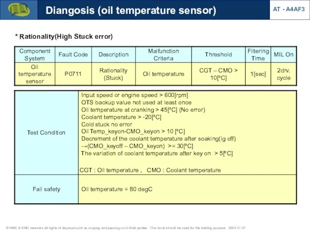
* Rationality(High Stuck error)
Diangosis (oil temperature sensor)
AT - A4AF3
* Rationality(High Stuck error)
Diangosis (oil temperature sensor)
AT - A4AF3
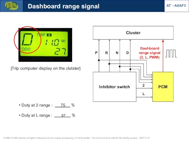
Dashboard range signal
AT - A4AF3
Cluster
Inhibitor switch
P
R
N
D
PCM
2
L
Dashboard range signal
(2, L, PWM)
[Trip computer
Dashboard range signal
AT - A4AF3
Cluster
Inhibitor switch
P
R
N
D
PCM
2
L
Dashboard range signal
(2, L, PWM)
[Trip computer
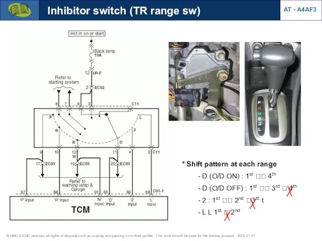
Inhibitor switch (TR range sw)
* Shift pattern at each range
- D
Inhibitor switch (TR range sw)
* Shift pattern at each range - D
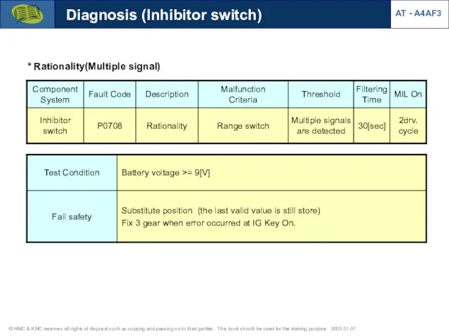
* Rationality(Multiple signal)
Diagnosis (Inhibitor switch)
AT - A4AF3
* Rationality(Multiple signal)
Diagnosis (Inhibitor switch)
AT - A4AF3
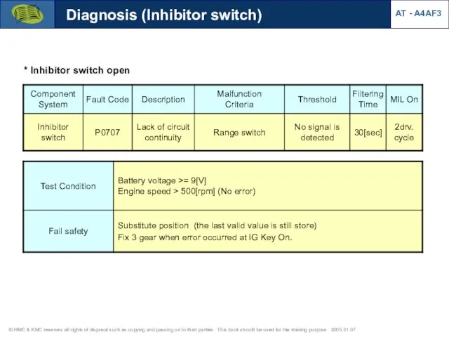
* Inhibitor switch open
Diagnosis (Inhibitor switch)
AT - A4AF3
* Inhibitor switch open
Diagnosis (Inhibitor switch)
AT - A4AF3

AT - A4AF3
Diagnosis (Inhibitor switch)
1. Application : A4AF3
2. Objectives
- To
AT - A4AF3
Diagnosis (Inhibitor switch)
1. Application : A4AF3
2. Objectives
- To

AT - A4AF3
Diagnosis (Inhibitor switch)
1. Application : A4AF3
2. Objectives
- To
AT - A4AF3
Diagnosis (Inhibitor switch)
1. Application : A4AF3
2. Objectives
- To

AT - A4AF3
Diagnosis (Inhibitor switch)
1. Application : A4AF3
2. Objectives
- To
AT - A4AF3
Diagnosis (Inhibitor switch)
1. Application : A4AF3
2. Objectives
- To

AT - A4AF3
Diagnosis (Inhibitor switch)
1. Application : A4AF3
2. Objectives
- To
AT - A4AF3
Diagnosis (Inhibitor switch)
1. Application : A4AF3
2. Objectives
- To
AT - A4AF3
Diagnosis (Inhibitor switch)
1. Application : A4AF3
2. Objectives
- To
AT - A4AF3
Diagnosis (Inhibitor switch)
1. Application : A4AF3
2. Objectives
- To
AT - A4AF3
Diagnosis (Inhibitor switch)
1. Application : A4AF3
2. Objectives
- To
AT - A4AF3
Diagnosis (Inhibitor switch)
1. Application : A4AF3
2. Objectives
- To
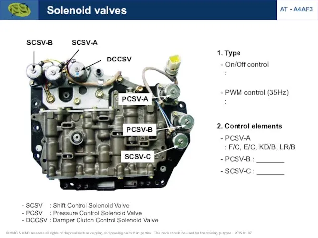
1. Type
- On/Off control
:
- PWM control (35Hz)
1. Type
- On/Off control
:
- PWM control (35Hz)
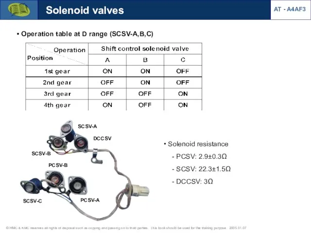
Solenoid valves
Operation table at D range (SCSV-A,B,C)
Solenoid resistance
-
Solenoid valves
Operation table at D range (SCSV-A,B,C)
Solenoid resistance -
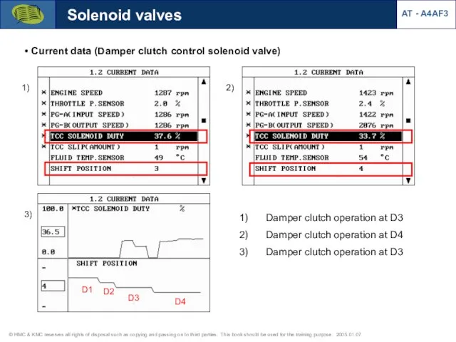
Solenoid valves
Current data (Damper clutch control solenoid valve)
D1
D2
D3
D4
Damper clutch operation
Solenoid valves
Current data (Damper clutch control solenoid valve)
D1
D2
D3
D4
Damper clutch operation
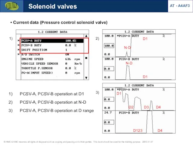
Solenoid valves
Current data (Pressure control solenoid valve)
N-D
D1
D1
N-D
D1
D2
D3
D4
D4
D123
1)
2)
PCSV-A, PCSV-B operation at
Solenoid valves
Current data (Pressure control solenoid valve)
N-D
D1
D1
N-D
D1
D2
D3
D4
D4
D123
1)
2)
PCSV-A, PCSV-B operation at
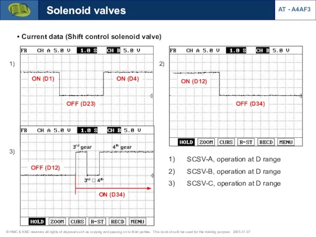
Solenoid valves
Current data (Shift control solenoid valve)
SCSV-A, operation at D
Solenoid valves
Current data (Shift control solenoid valve)
SCSV-A, operation at D
![Solenoid valves Circuit diagram [DCCSV duty signal] [PCSV-A duty signal-duty 100%] AT - A4AF3](/_ipx/f_webp&q_80&fit_contain&s_1440x1080/imagesDir/jpg/522476/slide-72.jpg)
Solenoid valves
Circuit diagram
[DCCSV duty signal]
[PCSV-A duty signal-duty 100%]
AT - A4AF3
Solenoid valves
Circuit diagram
[DCCSV duty signal]
[PCSV-A duty signal-duty 100%]
AT - A4AF3
![Diagnosis (solenoid valves) [Failsafe: 3rd gear hold at D,2,L] AT - A4AF3](/_ipx/f_webp&q_80&fit_contain&s_1440x1080/imagesDir/jpg/522476/slide-73.jpg)
Diagnosis (solenoid valves)
[Failsafe: 3rd gear hold at D,2,L]
AT - A4AF3
Diagnosis (solenoid valves)
[Failsafe: 3rd gear hold at D,2,L]
AT - A4AF3
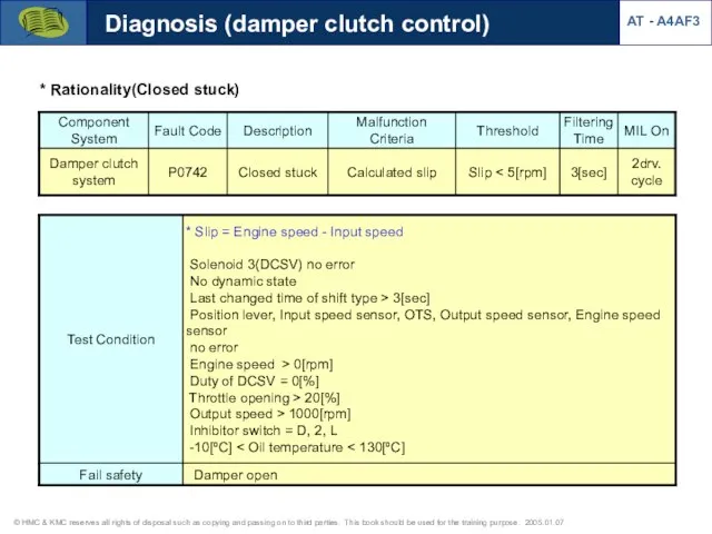
Diagnosis (damper clutch control)
AT - A4AF3
* Rationality(Closed stuck)
Diagnosis (damper clutch control)
AT - A4AF3
* Rationality(Closed stuck)
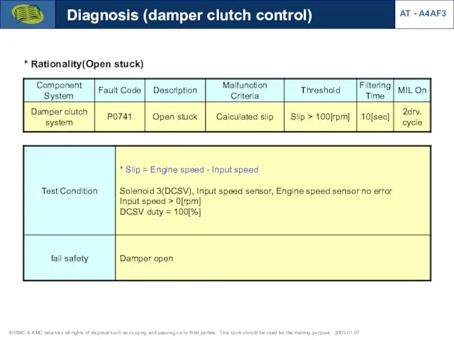
Diagnosis (damper clutch control)
AT - A4AF3
* Rationality(Open stuck)
Diagnosis (damper clutch control)
AT - A4AF3
* Rationality(Open stuck)
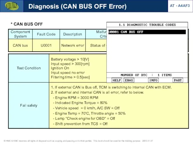
Diagnosis (CAN BUS OFF Error)
AT - A4AF3
* CAN BUS OFF
Diagnosis (CAN BUS OFF Error)
AT - A4AF3
* CAN BUS OFF
Diagnosis (CAN BUS OFF Error)
AT - A4AF3
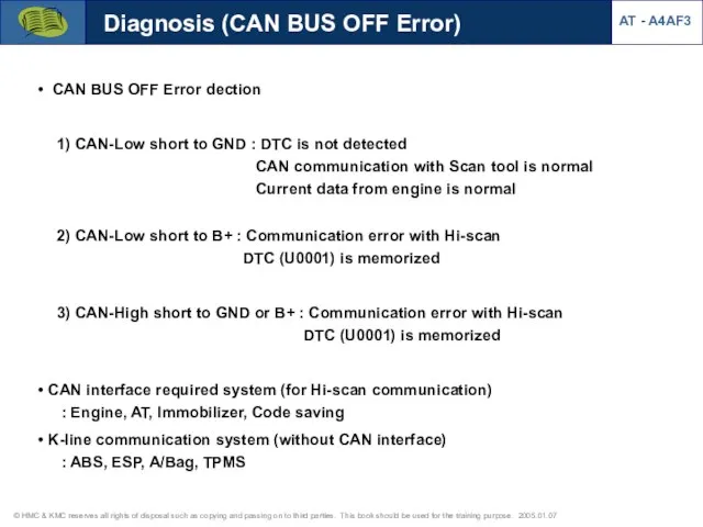
CAN BUS OFF Error
Diagnosis (CAN BUS OFF Error)
AT - A4AF3
CAN BUS OFF Error
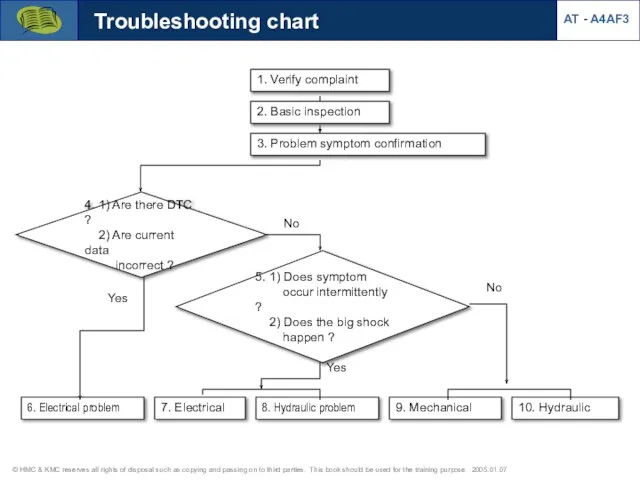
1. Verify complaint
3. Problem symptom confirmation
4. 1) Are there DTC ?
1. Verify complaint
3. Problem symptom confirmation
4. 1) Are there DTC ?
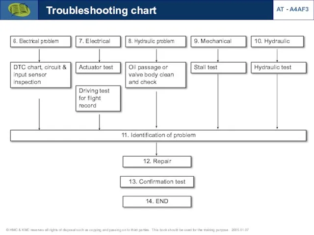
6. Electrical problem
7. Electrical
8. Hydraulic problem
9. Mechanical
10. Hydraulic
DTC chart,
6. Electrical problem
7. Electrical
8. Hydraulic problem
9. Mechanical
10. Hydraulic
DTC chart,
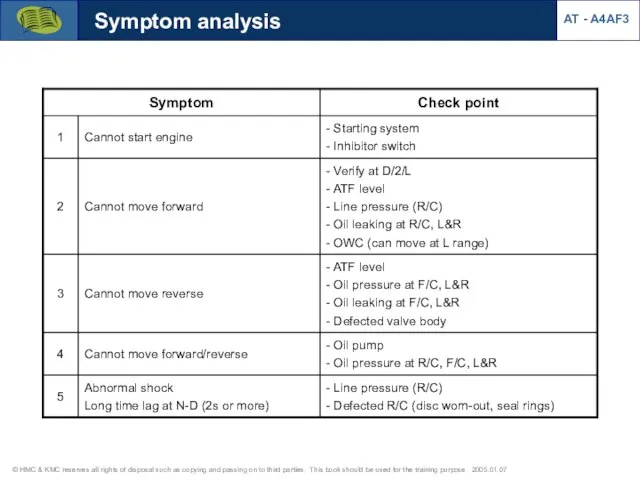
Symptom analysis
AT - A4AF3
Symptom analysis
AT - A4AF3
AT - A4AF3
Stall test
Shift range for stall test : D(1,3), L(1),
AT - A4AF3
Stall test
Shift range for stall test : D(1,3), L(1),
Pressure test
Pressure test range : D/2/L/R
Preparation
- Warm up the engine and
Pressure test
Pressure test range : D/2/L/R
Preparation
- Warm up the engine and
Pressure test
Pressure ports
AT - A4AF3
Reducing pressure
Kickdown wervo pressure
Rear clutch pressure
Front clutch
Pressure test
Pressure ports
AT - A4AF3
Reducing pressure
Kickdown wervo pressure
Rear clutch pressure
Front clutch
Pressure test
Diagnosis of test result
AT - A4AF3
Pressure test
Diagnosis of test result
AT - A4AF3
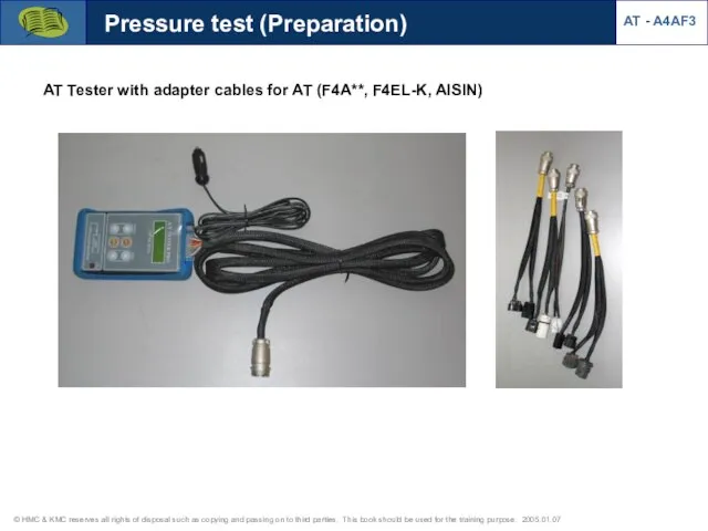
AT Tester with adapter cables for AT (F4A**, F4EL-K, AISIN)
Pressure test
AT Tester with adapter cables for AT (F4A**, F4EL-K, AISIN)
Pressure test
![Pressure sensor installation with AT Tester AT - A4AF3 [AT Tester]](/_ipx/f_webp&q_80&fit_contain&s_1440x1080/imagesDir/jpg/522476/slide-86.jpg)
Pressure sensor installation with AT Tester
AT - A4AF3
[AT Tester]
[Pressure control box]
[Pressure
Pressure sensor installation with AT Tester
AT - A4AF3
[AT Tester]
[Pressure control box]
[Pressure
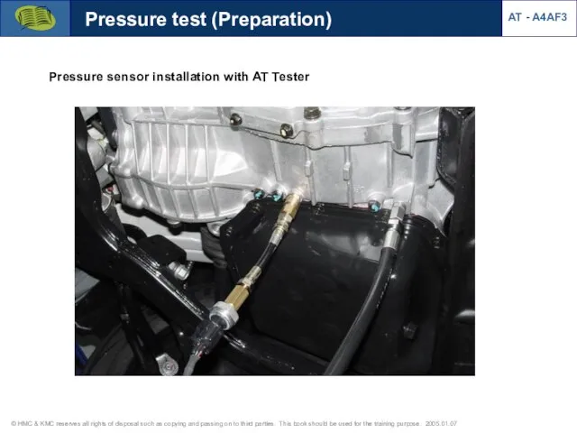
Pressure test (Preparation)
Pressure sensor installation with AT Tester
AT - A4AF3
Pressure test (Preparation)
Pressure sensor installation with AT Tester
AT - A4AF3
![[R/C pressure & PCSV-B operation at N?D?N] Pressure test 1) Rear](/_ipx/f_webp&q_80&fit_contain&s_1440x1080/imagesDir/jpg/522476/slide-88.jpg)
[R/C pressure & PCSV-B operation at N?D?N]
Pressure test
1) Rear clutch pressure
Rear
[R/C pressure & PCSV-B operation at N?D?N]
Pressure test
1) Rear clutch pressure
Rear
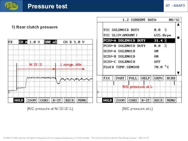
AT - A4AF3
Pressure test
1) Rear clutch pressure
N?D?2
L range, idle
[R/C pressure at
AT - A4AF3
Pressure test
1) Rear clutch pressure
N?D?2
L range, idle
[R/C pressure at
Pressure test
Damper clutch pressure (Waveform from pressure sensor)
[At P,N range]
[At R
Pressure test
Damper clutch pressure (Waveform from pressure sensor)
[At P,N range]
[At R
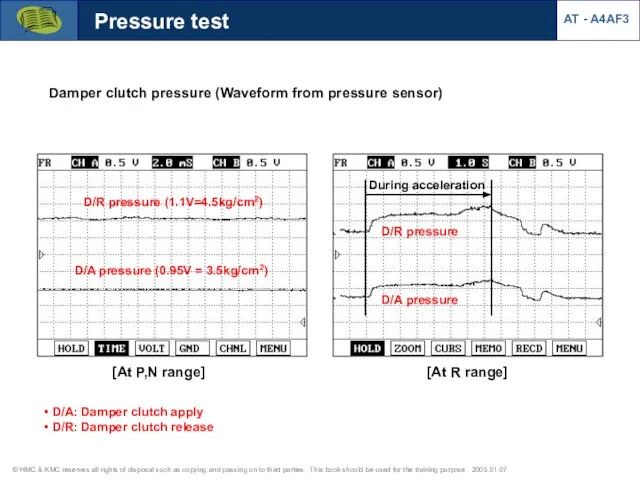
![Damper clutch pressure Pressure test [At D range] Damper clutch pressure](/_ipx/f_webp&q_80&fit_contain&s_1440x1080/imagesDir/jpg/522476/slide-91.jpg)
Damper clutch pressure
Pressure test
[At D range]
Damper clutch pressure (Waveform from pressure
Damper clutch pressure
Pressure test
[At D range]
Damper clutch pressure (Waveform from pressure
![Pressure test [At 2 range] [At L range] Damper clutch pressure](/_ipx/f_webp&q_80&fit_contain&s_1440x1080/imagesDir/jpg/522476/slide-92.jpg)
Pressure test
[At 2 range]
[At L range]
Damper clutch pressure (Waveform from pressure
Pressure test
[At 2 range]
[At L range]
Damper clutch pressure (Waveform from pressure
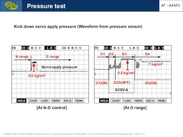
Pressure test
Kick down servo apply pressure (Waveform from pressure sensor)
[At N-D
Pressure test
Kick down servo apply pressure (Waveform from pressure sensor)
[At N-D
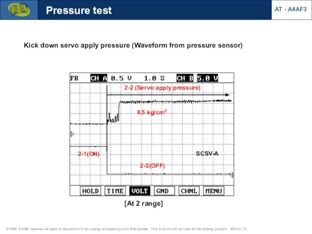
Kick down servo apply pressure (Waveform from pressure sensor)
Pressure test
2-2 (Servo
Kick down servo apply pressure (Waveform from pressure sensor)
Pressure test
2-2 (Servo
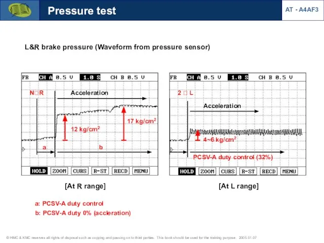
L&R brake pressure (Waveform from pressure sensor)
Pressure test
[At R range]
N?R
[At L
L&R brake pressure (Waveform from pressure sensor)
Pressure test
[At R range]
N?R
[At L
 Kultūras cilvēka dienasgrāmata
 Основные требования к размещению и креплению грузов в вагонах и контейнерах
 Урбанизация. Линейные объекты
 Фотоальбом 1
 Ojciec Święty Jan Paweł II
 Мощение дорожки в газоне экопарковки
 Электропривод и автоматизация промышленных установок и технологических комплексов
 Несчастные случаи на Одесском Авиационном Заводе 2000-2015 годы
 20130325_parlamentarizm_v_rossii
 Монтаж электропроводок
 История одного лета
 25_08_PREZENTATsIYa
 Расчёт трёхшарнирных систем
 20120807_hazary
 Оригами Кошка
 Компетенции современного учителя, способы формирования
 ВКР: Автоматизация производства жидкой углекислоты
 Сотрудничество педагогов и семьями воспитанников через создание закрытой группы вконтакте мы в детском саду
 Презентация для поминок
 20140204_muzykalnyy_kaleydoskop
 Отбор устьевой пробы
 Prezentatsia5
 Экстрасистолии: диагностика, лечение, профилактика
 the 37th lesson kid`s box3
 Технология получения препаратов тетрациклина
 Урок 1.Алгоритм и его свойства
 Известные актеры (фотографии)
 Базовый стенд ЦПС