- Basic Programming Simatic S7-300

Содержание
- 2. SIMATIC Overview
- 3. SIMATIC Controller (PLC) S7-200 S7-300 S7-400
- 4. S7 – 300 Features : Modular small controll system Performance graded range of CPU Extensive selection
- 5. S7 – 300 MRES = Memory reset function STOP = Stop mode, program not executed RUN
- 6. Starting with SIMATIC Manager
- 7. SIMATIC Manager menus and toolbars
- 8. Standard Library
- 9. Context-Sensitive Help in S7 F1
- 10. Creating a project
- 11. Insert Station
- 12. Starting Hardware Configuration Editor
- 13. Generating a Hardware setpoint Configuration
- 14. Addressing S7 Modules
- 15. Module Address Overview
- 16. Variable Addressing 2x
- 17. CPU Properties 2x
- 18. Saving the HW Configuration and Downloading it in the Module
- 19. Inserting S7 Block
- 20. Inserting S7 Block
- 21. Block architecture and Block editor OB : Organization Block FB : Function Block FC : Function
- 22. Program Structure
- 23. Binary Operation AND - OPERATION ASSIGNMENT
- 24. Binary Operation OR - OPERATION
- 25. EXCLUSIVE - OR - OPERATION Binary Operation
- 26. Binary Operation RESET DOMINANT SET DOMINANT
- 27. Binary Operation POSITIVE EDGE
- 28. Binary Operation NEGATIVE EDGE
- 29. Binary Operation JUMP UNCONDITIONAL (JU) JUMP CONDITIONAL (JC)
- 30. Digital Operation BIT BYTE WORD For a unit of 8 binary characters, the term BYTE is
- 31. Beberapa operand di S7 : Operand input(I) Bit I 0.0 - … Byte IB 0 -
- 32. PULSE TIMER Digital Operation
- 33. EXTENDED PULSE TIMER Digital Operation
- 34. ON –DELAY TIMER Digital Operation
- 35. OFF-DELAY TIMER Digital Operation
- 36. COUNTER OPERATIONS Digital Operation
- 37. COMPARISON FUNCTIONS Digital Operation == IN1 is equal to IN2 IN1 is not equal to IN2
- 38. Digital Operation
- 39. ??? Data Block
- 40. ??? Scale & Unscaled
- 42. Скачать презентацию
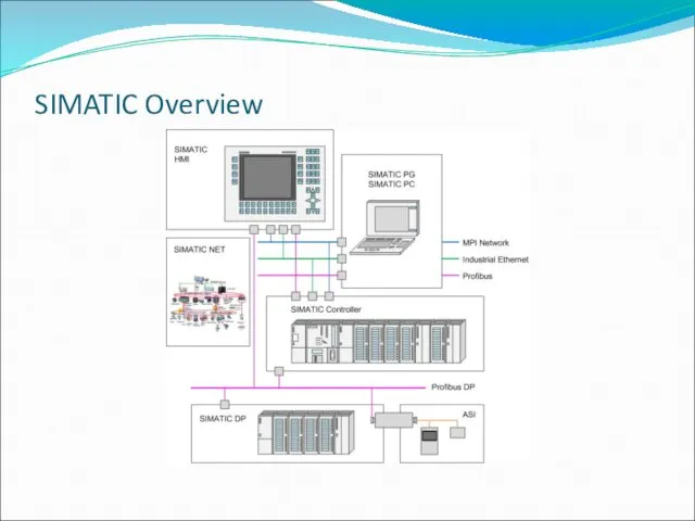
SIMATIC Overview
SIMATIC Overview
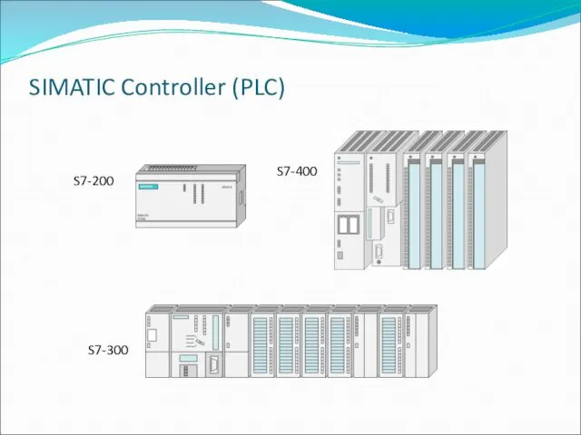
SIMATIC Controller (PLC)
S7-200
S7-300
S7-400
SIMATIC Controller (PLC)
S7-200
S7-300
S7-400
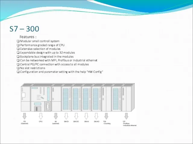
S7 – 300
Features :
Modular small controll system
Performance graded range
S7 – 300
Features :
Modular small controll system
Performance graded range
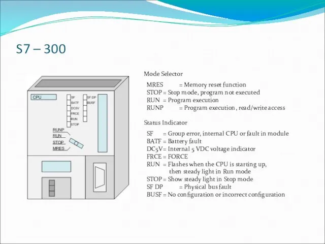
S7 – 300
MRES = Memory reset function
STOP = Stop mode, program not executed
RUN =
S7 – 300
MRES = Memory reset function
STOP = Stop mode, program not executed
RUN =
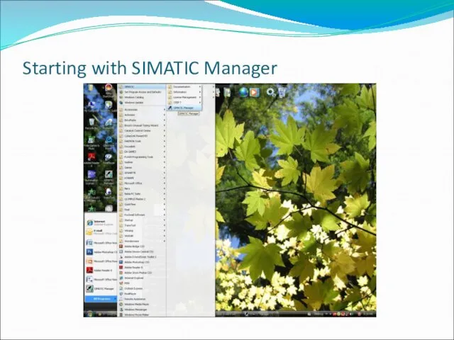
Starting with SIMATIC Manager
Starting with SIMATIC Manager
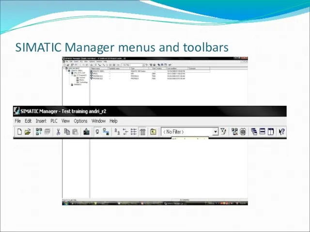
SIMATIC Manager menus and toolbars
SIMATIC Manager menus and toolbars
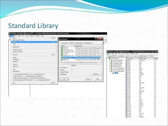
Standard Library
Standard Library
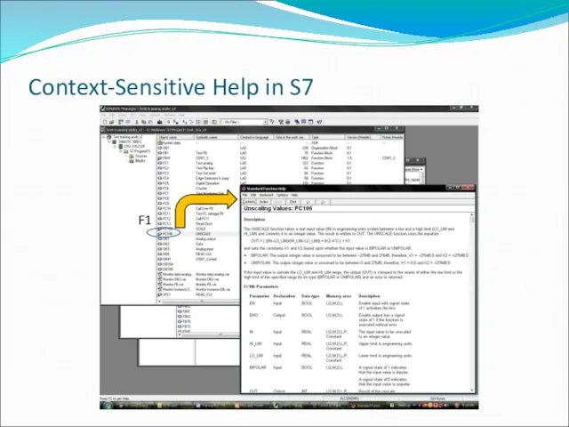
Context-Sensitive Help in S7
F1
Context-Sensitive Help in S7
F1
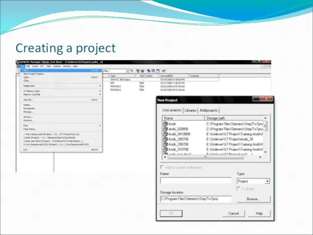
Creating a project
Creating a project
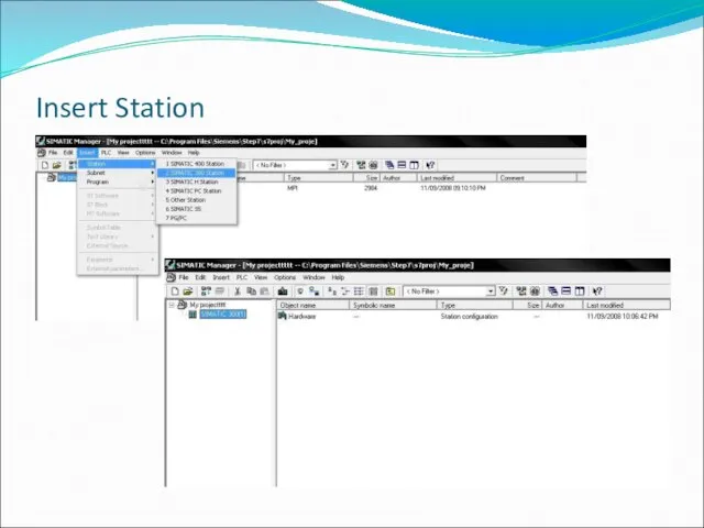
Insert Station
Insert Station
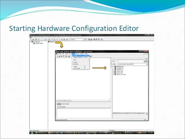
Starting Hardware Configuration Editor
Starting Hardware Configuration Editor
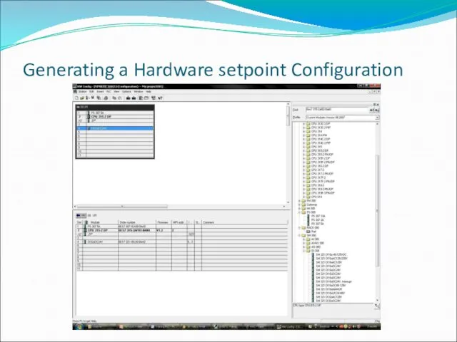
Generating a Hardware setpoint Configuration
Generating a Hardware setpoint Configuration
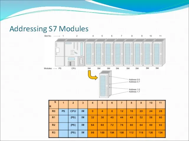
Addressing S7 Modules
Addressing S7 Modules
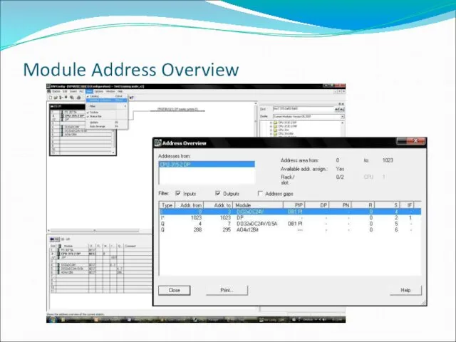
Module Address Overview
Module Address Overview
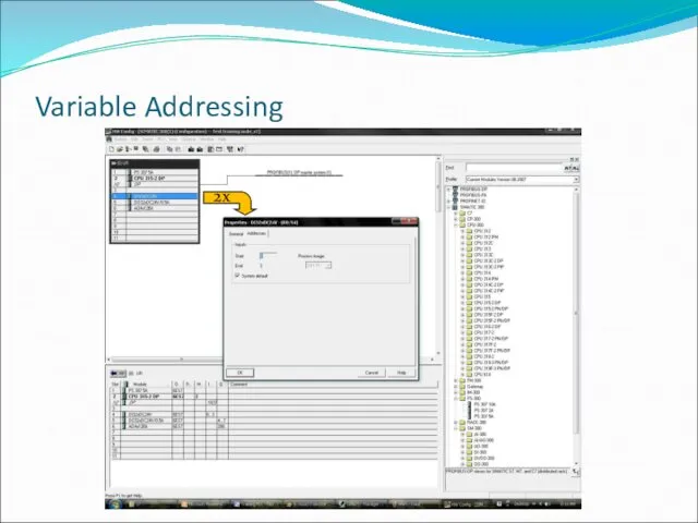
Variable Addressing
2x
Variable Addressing
2x
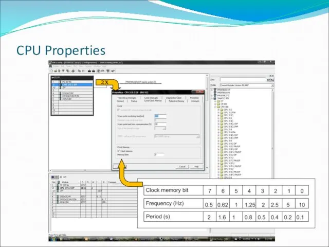
CPU Properties
2x
CPU Properties
2x
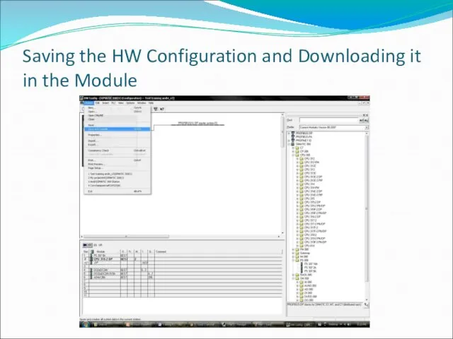
Saving the HW Configuration and Downloading it in the Module
Saving the HW Configuration and Downloading it in the Module
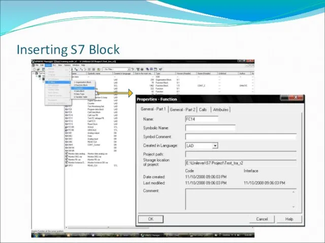
Inserting S7 Block
Inserting S7 Block
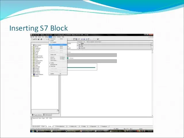
Inserting S7 Block
Inserting S7 Block
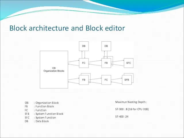
Block architecture and Block editor
OB : Organization Block
FB : Function Block
FC : Function
SFB : System
Block architecture and Block editor
OB : Organization Block
FB : Function Block
FC : Function
SFB : System
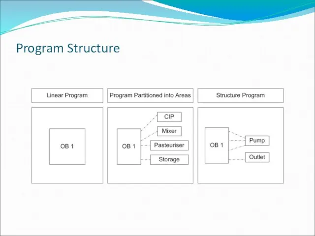
Program Structure
Program Structure
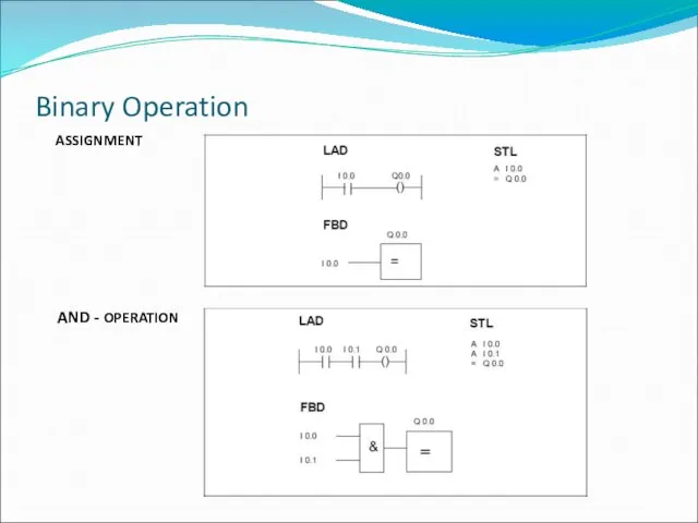
Binary Operation
AND - OPERATION
ASSIGNMENT
Binary Operation
AND - OPERATION
ASSIGNMENT
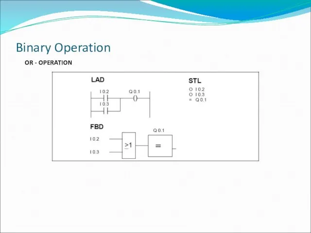
Binary Operation
OR - OPERATION
Binary Operation
OR - OPERATION
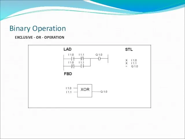
EXCLUSIVE - OR - OPERATION
Binary Operation
EXCLUSIVE - OR - OPERATION
Binary Operation
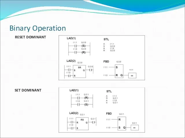
Binary Operation
RESET DOMINANT
SET DOMINANT
Binary Operation
RESET DOMINANT
SET DOMINANT

Binary Operation
POSITIVE EDGE
Binary Operation
POSITIVE EDGE
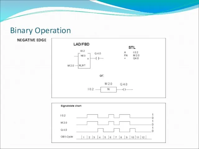
Binary Operation
NEGATIVE EDGE
Binary Operation
NEGATIVE EDGE
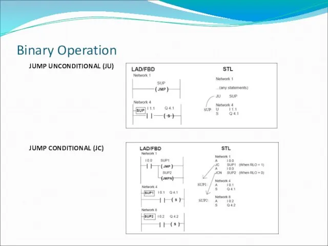
Binary Operation
JUMP UNCONDITIONAL (JU)
JUMP CONDITIONAL (JC)
Binary Operation
JUMP UNCONDITIONAL (JU)
JUMP CONDITIONAL (JC)
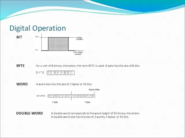
Digital Operation
BIT
BYTE
WORD
For a unit of 8 binary characters,
Digital Operation
BIT
BYTE
WORD
For a unit of 8 binary characters,
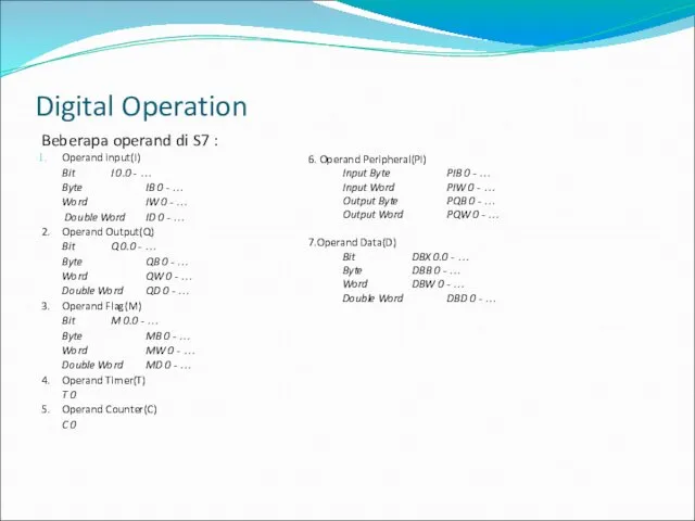
Beberapa operand di S7 :
Operand input(I)
Bit I 0.0 - …
Byte IB 0
Beberapa operand di S7 :
Operand input(I)
Bit I 0.0 - …
Byte IB 0
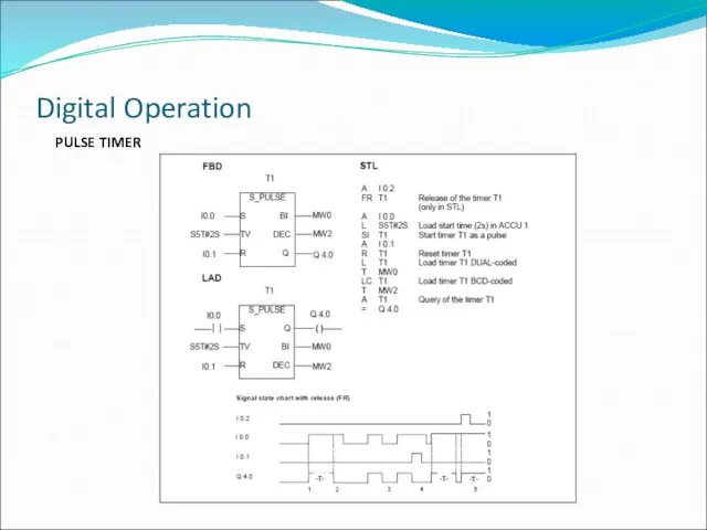
PULSE TIMER
Digital Operation
PULSE TIMER
Digital Operation
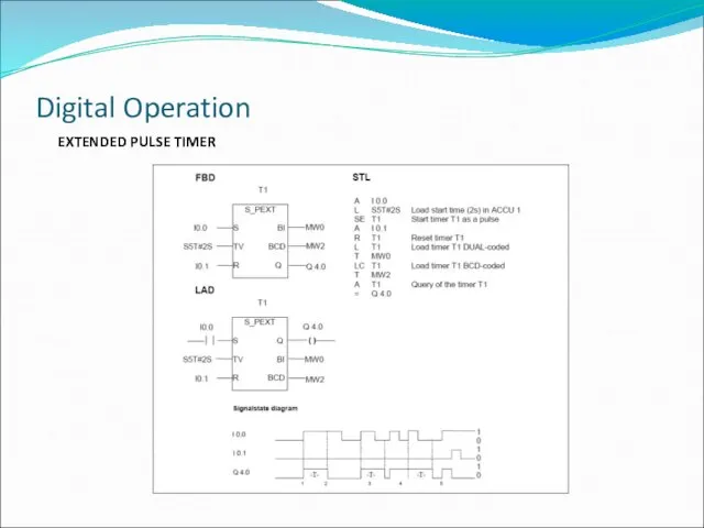
EXTENDED PULSE TIMER
Digital Operation
EXTENDED PULSE TIMER
Digital Operation
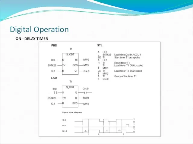
ON –DELAY TIMER
Digital Operation
ON –DELAY TIMER
Digital Operation
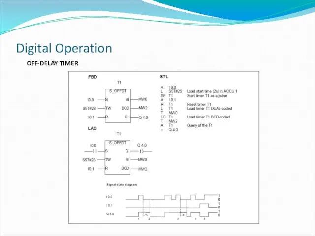
OFF-DELAY TIMER
Digital Operation
OFF-DELAY TIMER
Digital Operation
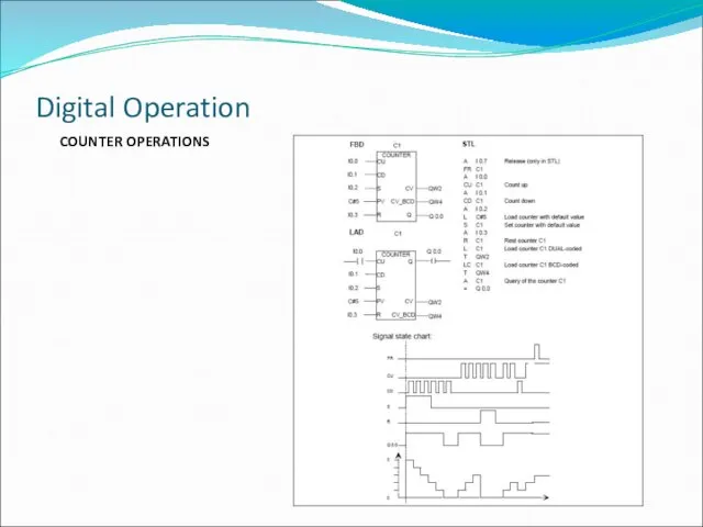
COUNTER OPERATIONS
Digital Operation
COUNTER OPERATIONS
Digital Operation
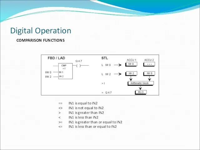
COMPARISON FUNCTIONS
Digital Operation
== IN1 is equal to IN2
<> IN1 is not equal
COMPARISON FUNCTIONS
Digital Operation
== IN1 is equal to IN2
<> IN1 is not equal
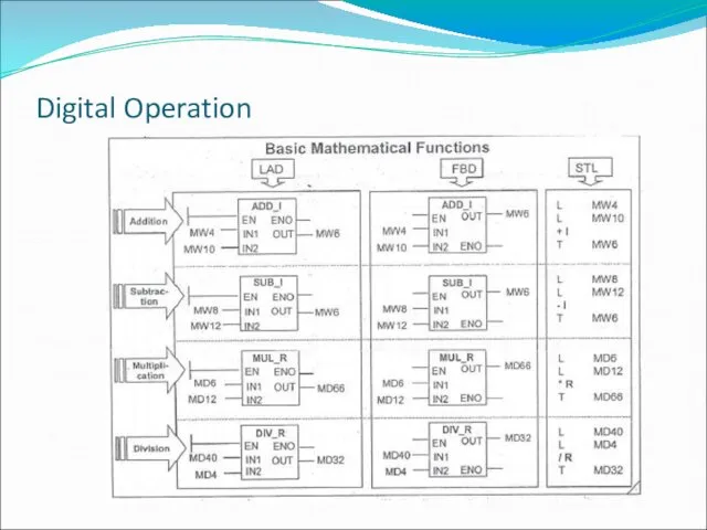
Digital Operation
Digital Operation

???
Data Block
???
Data Block

???
Scale & Unscaled
???
Scale & Unscaled
 20120726_metamorfozy_olega_shuplyaka_prodolzhenie
 Эффективные упражнения для глаз
 ТЭС - теплоэлектростанция
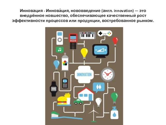 20150527_innovatsionnyy_peterburg
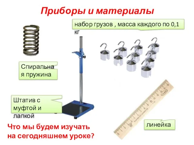 Приборы и материалы
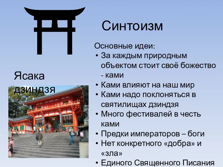 Ясака дзиндзя. Синтоизм
 педсовет Взаимод с семьей
 Виды роботов
 Техническая эксплуатация и обслуживание железнодорожного хладотранспорта
 Стили рекламного обращения
 20130318_religiya
 Designer
 International Pancake Day
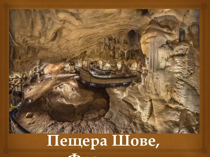 Пещера Шове
 Г. Белль. Подорожній коли ти прийдеш у Спа
 Ты моя звездочка
 ДНЦ
ДНЦ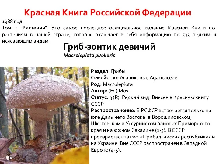 Мир грибов. 5, 6, 7 пункты
 Safety in Grinding
 ребус
ребус Фасовочно-упаковочное оборудование
 Крепость-герой Брест. Монумент Мужество
 20180214_viktorina_po_pdd
 Перспективы деятельности АО УНТК
 Псалом 29. Воспою хвалу Тебе, Господи, бо вознёс меня и опечалил врагов моих
 Основы развития малоэтажного градостроительства. (Лекция 6)
 Миллионер. Игра
 20140818_prezentatsiya_triik_1_-_kopiya