- Training FM850

Содержание
- 2. FM850 FM850 Participant: John Do Johny Does Joe Did Joey Dun
- 3. FM850 FM850 TAKE CONTROL OF YOUR MACHINE
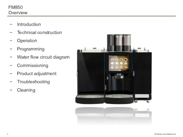
- 4. FM850 Overview Introduction Technical construction Operation Programming Water flow circuit diagram Commissioning Product adjustment Troubleshooting Cleaning
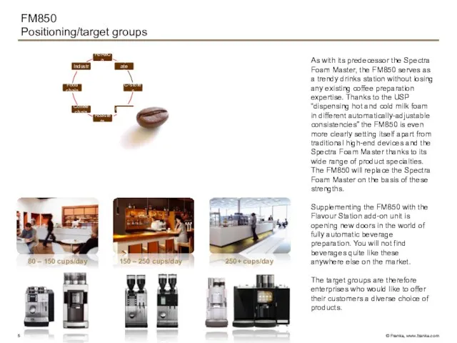
- 5. FM850 Positioning/target groups As with its predecessor the Spectra Foam Master, the FM850 serves as a
- 6. Introduction Dimensions FM850 800 mm 300 mm 300 mm 712 mm 70-180 mm 520 mm 200
- 7. Introduction Features PERFORMANS (DOUBLE CUP) / OUTPUT PER HOUR PER DIN 18873-2 Espresso 162 (232) Coffee
- 8. Introduction Machine overview Powder dosing unit with one or two chambers (instead of the left grinder)
- 9. Introduction Available version and options BASIC MODEL FM850 with one grinder hot water dispenser Black Line
- 10. Introduction Model code Example FM850 model code: T 2M 1P H FM KE300
- 11. Introduction Scope of delivery Base fastener Grinder adjusting Water connection gasket Cleaning brush Key Operating instruction
- 12. Introduction Hygiene Short milk tubes between refrigerator and coffee machine Milk pumps in the refrigerator Improved
- 13. Introduction Vetro Touch REVOLUTIONARY TOUCHSCREEN The FM850 is revolutionizing the world of coffee machines with its
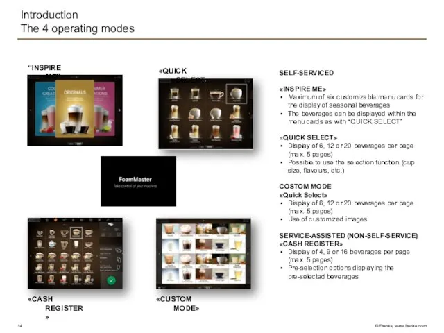
- 14. Introduction The 4 operating modes SELF-SERVICED «INSPIRE ME» Maximum of six customizable menu cards for the
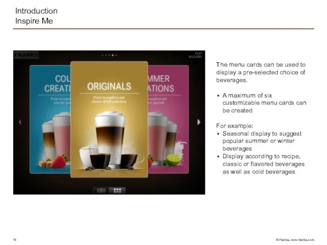
- 15. Introduction Inspire Me The menu cards can be used to display a pre-selected choice of beverages.
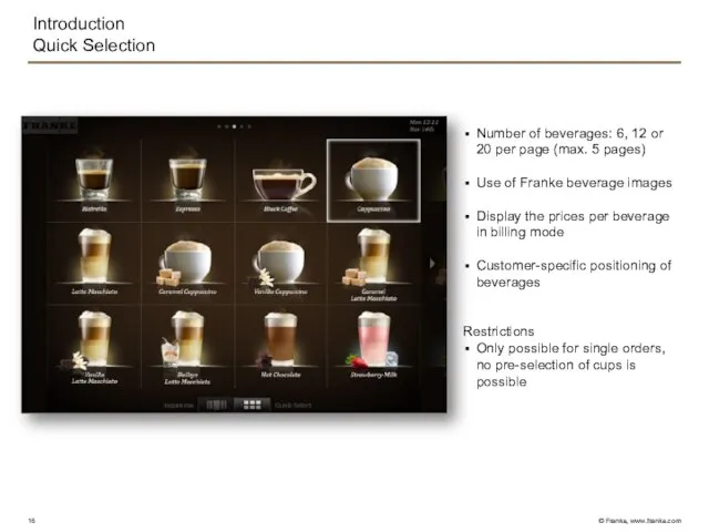
- 16. Introduction Quick Selection Number of beverages: 6, 12 or 20 per page (max. 5 pages) Use
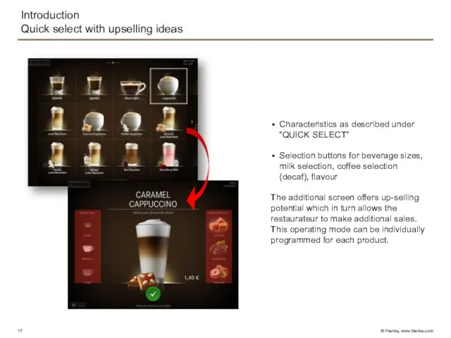
- 17. Introduction Quick select with upselling ideas Characteristics as described under “QUICK SELECT” Selection buttons for beverage
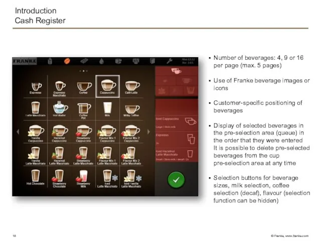
- 18. Introduction Cash Register Number of beverages: 4, 9 or 16 per page (max. 5 pages) Use
- 19. Customers can customize the “QUICK SELECT” mode by uploading their own images to create their own
- 20. Error messages generally appear in the dashboard and light up in different colours. A detailed description
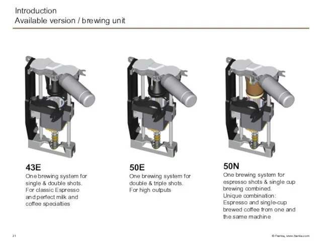
- 21. 43E One brewing system for single & double shots. For classic Espresso and perfect milk and
- 22. Technical construction Overview Water connection Pump Valves (Plastic) Heating unit Thermoblock Cold water valve block Flow
- 23. Technical construction Water connection Water flow Y33 Filter filter Pressure main water 80-800Pa 0.8 – 8
- 24. Technical construction Pump Water flow RV M2 Cold water valve block Bypass Bypass Adjustment of water
- 25. Technical construction 2/2- way plastic valve 1) 2) 3) 4) 6) 5) 7) 9) 10) a)
- 26. Technical construction 3/2 way plastic valve 1) 2) 3) 4) 6) 5) 7) 8) 9) Coil
- 27. Technical construction Heating unit V3 2 3 4 1 2 3 6 5 1 7 8
- 28. Technical construction Heating unit V3 1) 2) 3) 4) 5) 6) 7) 8) 9) 10) 11)
- 29. Technical construction Thermoblock 7) 6) 5) 4) 3) 2) 1) Thermoblock module Holding cone Thermal fuse
- 30. Technical construction Thermoblock Water flow Electrical 230Vac N bk H3 bu K3 b a Thermal Fuse
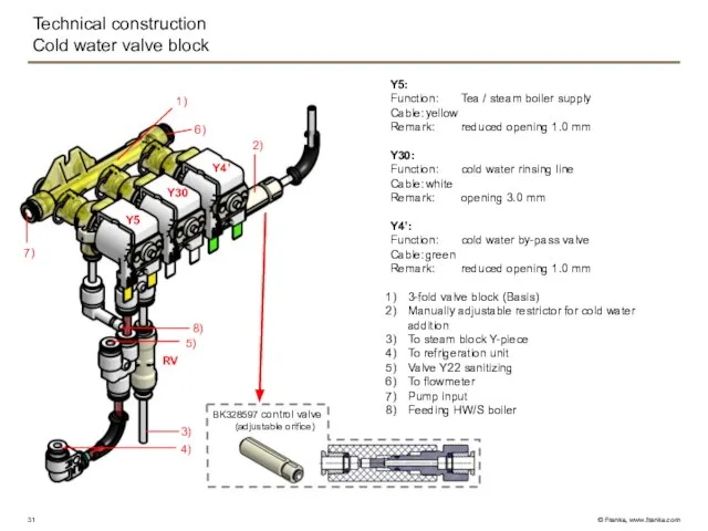
- 31. Technical construction Cold water valve block Y30 Y4’ Y5 RV 1) 2) 3) 4) 8) 6)
- 32. Technical construction Cold water valve block GND +24V DCs Power board X14.22 X14.11 X14.20 X14.9 X14.21
- 33. Flow meter: From cold water block To pressure gauge Coffee boiler supply Flow meter Check valve
- 34. Technical construction Coffee boiler, 2.5kW (0.9l) Safety valve12 bar (Spectra) NTC temperature sensor Coffee boiler supply
- 35. Technical construction Coffee boiler 2.5kW Water flow Electrical N rd H1 bl K2 b a Thermal
- 36. Technical construction Hot water valve block Hot water valve block: Y22: Function: hot water rinsing line
- 37. Technical construction Hot water valve block GND +24V DCs Power board X14.18 X14.7 X13.4 X13.1 X14.15
- 38. Technical construction Tea / steam boiler, 2.5kW (0.9l/0.6l) NTC temperature sensor Level sensor l=84 mm Hot
- 39. Technical construction Tea / steam boiler, 2.5kW Water flow Electrical N gy H2 bu K2 b
- 40. Technical construction Steam valve block Y6: Function: Autosteam (3/2-way valve) Cable: brown Marking: white, opening 3.0
- 41. Technical construction Steam valve block GND +24V DCs Power board X14.19 X14.8 X14.17 X14.6 bn bn
- 42. Technical construction Hot water valve 1) 2) 3) 4) Y4: Function: hot water/tea Cable: blue Remark:
- 43. Technical construction Steam valve block GND +24V DCs Power board X14.16 X14.5 wt wt Y4 Water
- 44. Technical construction Drainage valve Y39: Function: drainage Cable: green To outlet From thermoblock To bulkhead connection
- 45. Technical construction Steam valve block GND +24V DCs Power board X26.16 X26.8 gn gn Y39 Water
- 46. Technical construction Brewing Unit 43E / 50E / 50N 43E 50E 50N 1) 3) 2) Light
- 47. Technical construction Brewing Unit Water flow Electrical Power board N 230Vac-X Brewing chamber heater Encoder /
- 48. Technical construction Fixed increment positions 100 Increments E 042 E 043 E 041 E 044 Lower
- 49. Technical construction Coffee outlet Distributor FM: Cold or hot milk Coffee 1) 2) 3) 4) Coffee
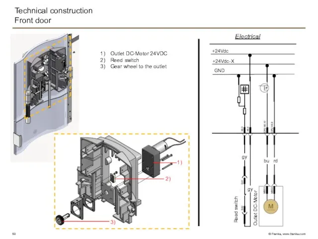
- 50. Technical construction Front door Outlet DC-Motor 24VDC Reed switch Gear wheel to the outlet Electrical Outlet
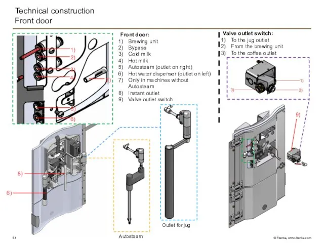
- 51. Technical construction Front door Front door: Brewing unit Bypass Cold milk Hot milk Autosteam (outlet on
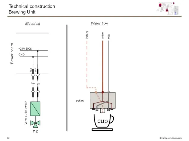
- 52. Technical construction Brewing Unit Power board Water flow Electrical outlet coffee cup milk GND +24V DCs
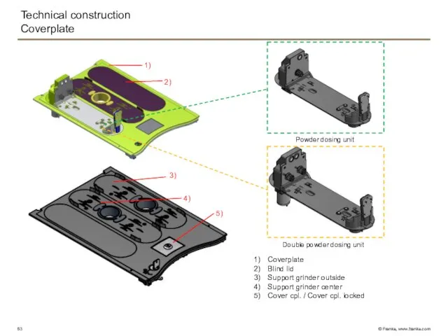
- 53. Technical construction Coverplate 1) 2) 3) 4) Coverplate Blind lid Support grinder outside Support grinder center
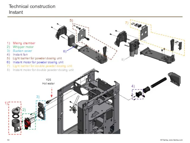
- 54. Technical construction Instant Y25 Hot water 1) 2) 3) 4) 5) 7) 8) 6) Mixing chamber
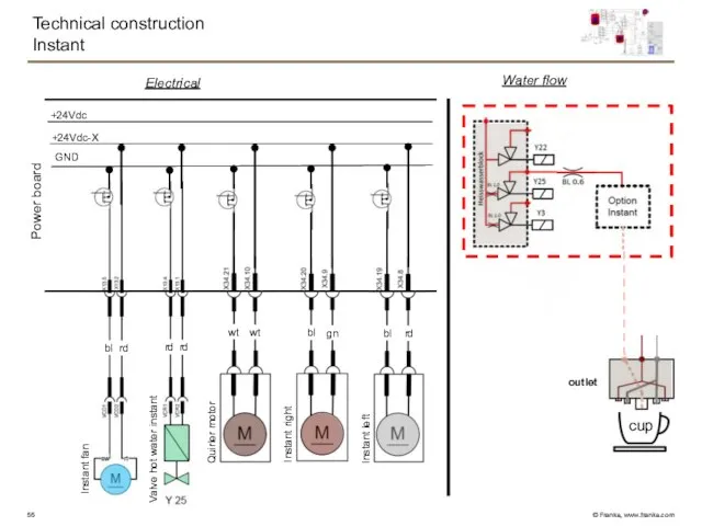
- 55. Technical construction Instant Electrical GND +24Vdc-X +24Vdc Instant fan Valve hot water instant Quirler motor Instant
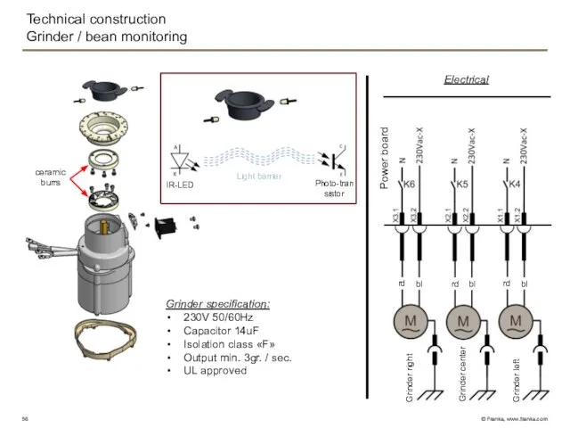
- 56. Technical construction Grinder / bean monitoring ceramic burrs Grinder specification: 230V 50/60Hz Capacitor 14uF Isolation class
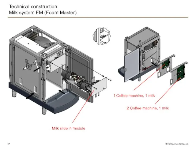
- 57. Technical construction Milk system FM (Foam Master) 1 Coffee machine, 1 milk 2 Coffee machine, 1
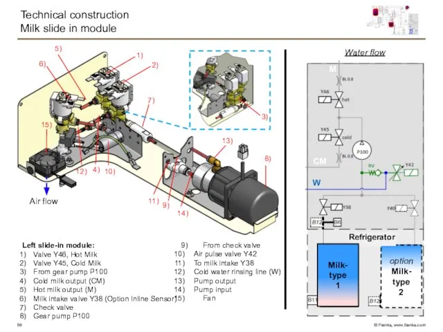
- 58. Technical construction Milk slide in module 9) From check valve Air pulse valve Y42 To milk
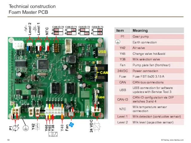
- 59. Technical construction Foam Master PCB USB CAN NTC Level 1 Level 2 Fuse 24 VDC Fan
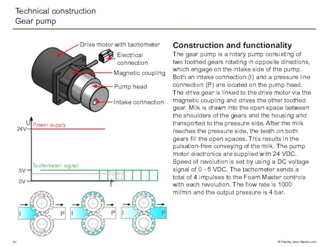
- 60. Technical construction Gear pump Construction and functionality The gear pump is a rotary pump consisting of
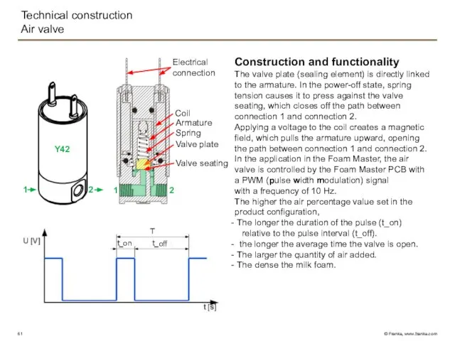
- 61. Technical construction Air valve Construction and functionality The valve plate (sealing element) is directly linked to
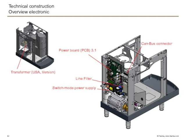
- 62. Technical construction Overview electronic Switch-mode power supply Power board (PCB) 3.1 Line Filter Transformer (USA, Version)
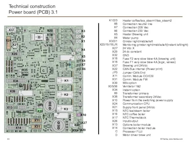
- 63. Technical construction Power board (PCB) 3.1 Heater coffee/tea_steam1/tea_steam2 Connection neutral line Connection 208 Vac Connection 230
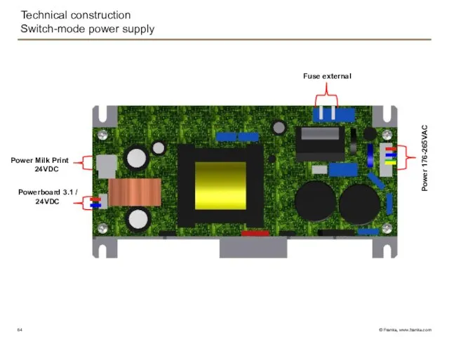
- 64. Technical construction Switch-mode power supply Power Milk Print 24VDC Powerboard 3.1 / 24VDC Power 176-265VAC Fuse
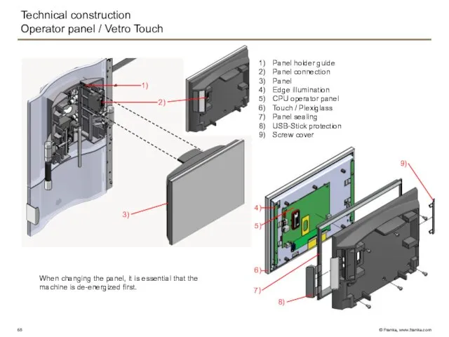
- 65. Technical construction Operator panel / Vetro Touch 1) 3) 2) Panel holder guide Panel connection Panel
- 66. Technical construction Flavour Station (Option) 5) Electrical part Peristaltic pump Drawer 2) 1) 3)
- 67. Technical construction Flavour Station / electrical part Function The switching power supply is supplied with mains
- 68. Technical construction Flavour Station / electrical part P1 P3 P2 24 VDC USB CAN Priming button
- 69. Technical construction Flavour Station / mechanical part Stepper motor Coupling Supporter of the motor Peristaltic pump
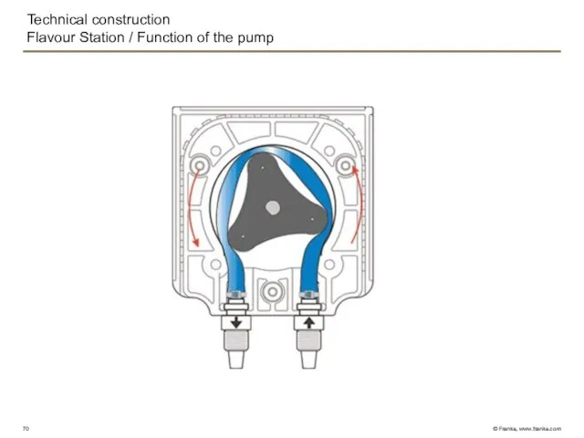
- 70. Technical construction Flavour Station / Function of the pump
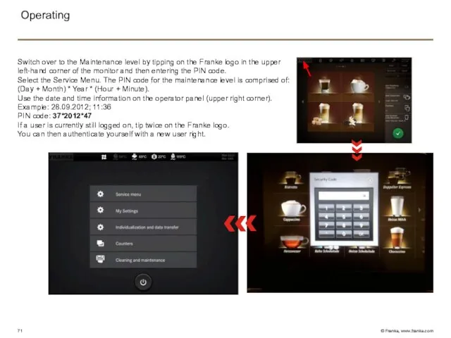
- 71. Operating Switch over to the Maintenance level by tipping on the Franke logo in the upper
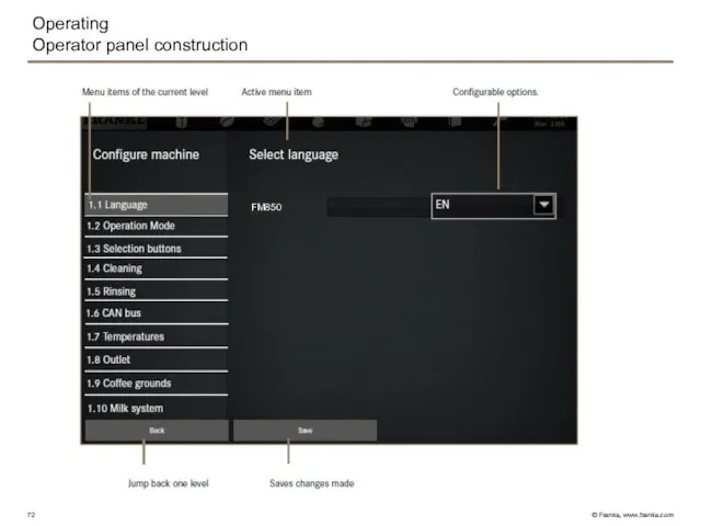
- 72. Operating Operator panel construction FM850
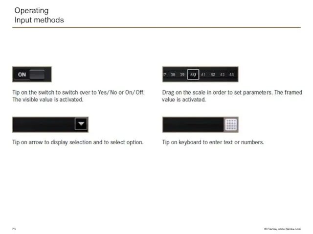
- 73. Operating Input methods
- 74. Programming Service Menu
- 75. Programming Commissioning FM850
- 76. Programming Configure machine FM850
- 77. Programming Set Drinks
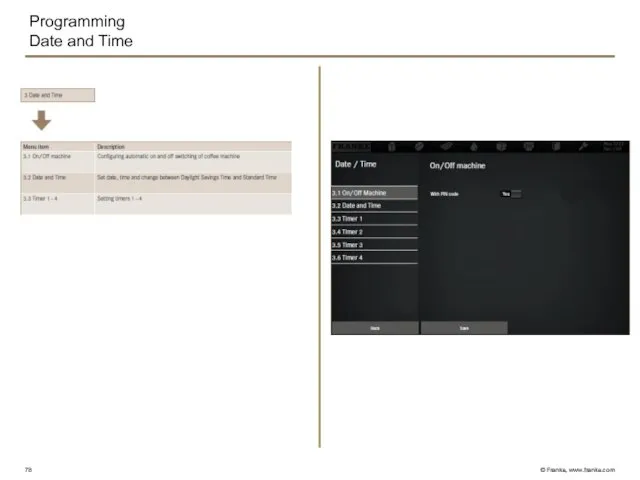
- 78. Programming Date and Time
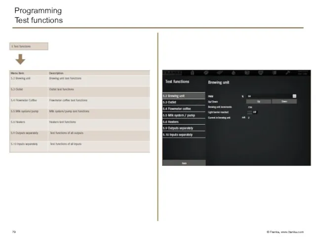
- 79. Programming Test functions
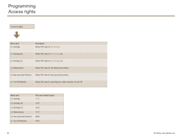
- 80. Programming Access rights
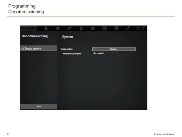
- 81. Programming Decommissioning
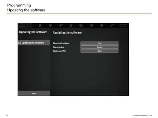
- 82. Programming Updating the software
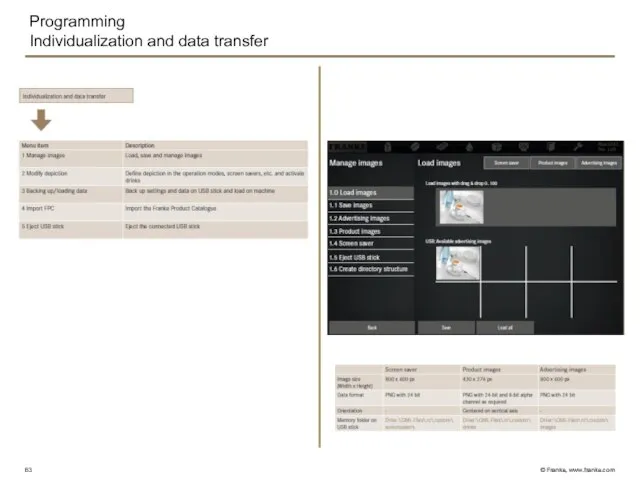
- 83. Programming Individualization and data transfer
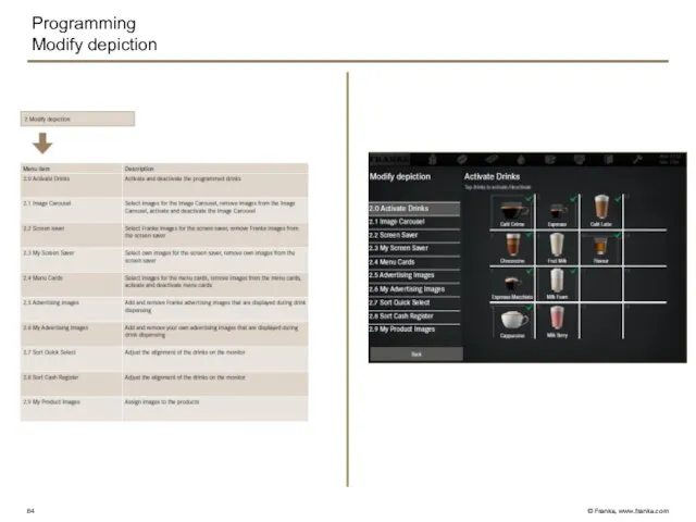
- 84. Programming Modify depiction
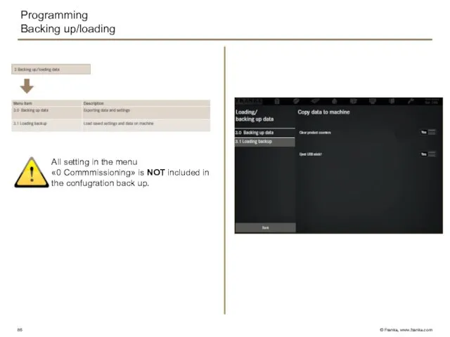
- 85. Programming Backing up/loading All setting in the menu «0 Commmissioning» is NOT included in the confugration
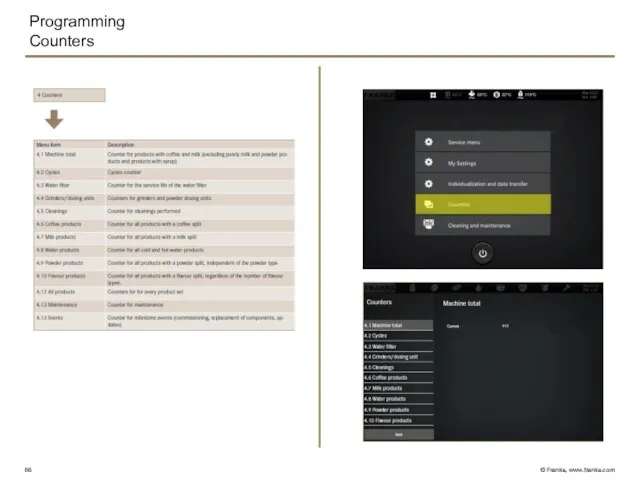
- 86. Programming Counters
- 87. Water flow circuit diagram Coffee boiler Outlet switch Instant system Coffee Cappu Tea Tea / steam
- 88. FM850 Commissioning Product adjustment Troubleshooting Cleaning
- 90. Скачать презентацию
FM850
FM850
Participant:
John Do
Johny Does
Joe Did
Joey Dun
FM850
FM850
Participant:
John Do
Johny Does
Joe Did
Joey Dun
FM850
FM850
TAKE CONTROL OF YOUR MACHINE
FM850
FM850
TAKE CONTROL OF YOUR MACHINE
FM850
Overview
Introduction
Technical construction
Operation
Programming
Water flow circuit diagram
Commissioning
Product adjustment
Troubleshooting
Cleaning
FM850
Overview
Introduction
Technical construction
Operation
Programming
Water flow circuit diagram
Commissioning
Product adjustment
Troubleshooting
Cleaning
FM850
Positioning/target groups
As with its predecessor the Spectra Foam Master, the FM850
FM850
Positioning/target groups
As with its predecessor the Spectra Foam Master, the FM850
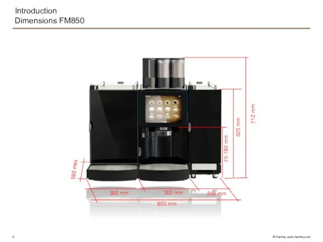
Introduction
Dimensions FM850
800 mm
300 mm
300 mm
712 mm
70-180 mm
520 mm
200 mm
580 mm
Introduction
Dimensions FM850
800 mm
300 mm
300 mm
712 mm
70-180 mm
520 mm
200 mm
580 mm
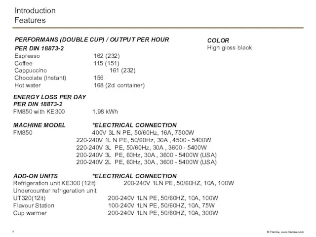
Introduction
Features
PERFORMANS (DOUBLE CUP) / OUTPUT PER HOUR
PER DIN 18873-2
Espresso 162 (232)
Coffee
Introduction
Features
PERFORMANS (DOUBLE CUP) / OUTPUT PER HOUR
PER DIN 18873-2
Espresso 162 (232)
Coffee
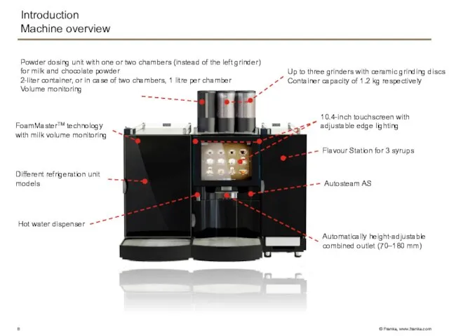
Introduction
Machine overview
Powder dosing unit with one or two chambers (instead of
Introduction
Machine overview
Powder dosing unit with one or two chambers (instead of
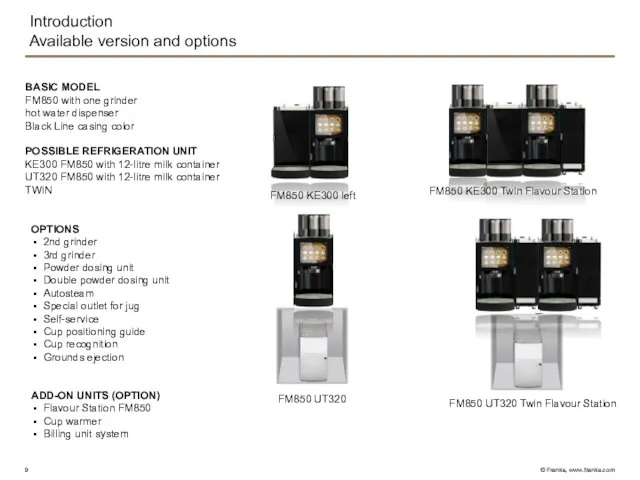
Introduction
Available version and options
BASIC MODEL
FM850 with one grinder
hot water dispenser
Black
Introduction
Available version and options
BASIC MODEL
FM850 with one grinder
hot water dispenser
Black
Introduction
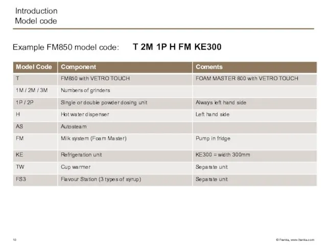
Model code
Example FM850 model code: T 2M 1P H FM KE300
Introduction
Model code
Example FM850 model code: T 2M 1P H FM KE300
Introduction
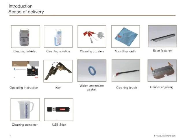
Scope of delivery
Base fastener
Grinder adjusting
Water connection gasket
Cleaning brush
Key
Operating instruction
Cleaning tablets
Cleaning solution
Cleaning
Introduction
Scope of delivery
Base fastener
Grinder adjusting
Water connection gasket
Cleaning brush
Key
Operating instruction
Cleaning tablets
Cleaning solution
Cleaning
Introduction
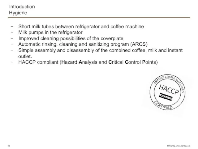
Hygiene
Short milk tubes between refrigerator and coffee machine
Milk pumps in the
Introduction
Hygiene
Short milk tubes between refrigerator and coffee machine
Milk pumps in the
Introduction
Vetro Touch
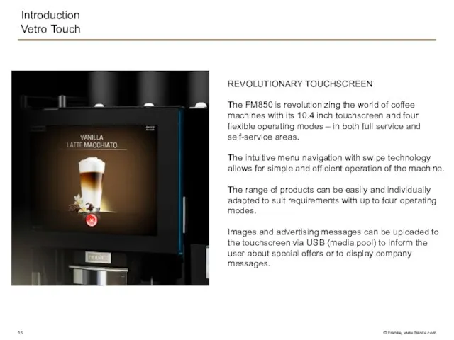
REVOLUTIONARY TOUCHSCREEN
The FM850 is revolutionizing the world of coffee machines
Introduction
Vetro Touch
REVOLUTIONARY TOUCHSCREEN
The FM850 is revolutionizing the world of coffee machines
Introduction
The 4 operating modes
SELF-SERVICED
«INSPIRE ME»
Maximum of six customizable menu cards
Introduction
The 4 operating modes
SELF-SERVICED
«INSPIRE ME»
Maximum of six customizable menu cards
Introduction
Inspire Me
The menu cards can be used to display a pre-selected
Introduction
Inspire Me
The menu cards can be used to display a pre-selected
Introduction
Quick Selection
Number of beverages: 6, 12 or 20 per page (max.
Introduction
Quick Selection
Number of beverages: 6, 12 or 20 per page (max.
Introduction
Quick select with upselling ideas
Characteristics as described under “QUICK SELECT”
Selection buttons
Introduction
Quick select with upselling ideas
Characteristics as described under “QUICK SELECT”
Selection buttons
Introduction
Cash Register
Number of beverages: 4, 9 or 16 per page (max.
Introduction
Cash Register
Number of beverages: 4, 9 or 16 per page (max.
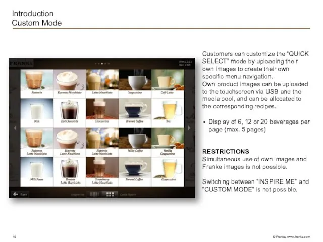
Customers can customize the “QUICK SELECT” mode by uploading their own
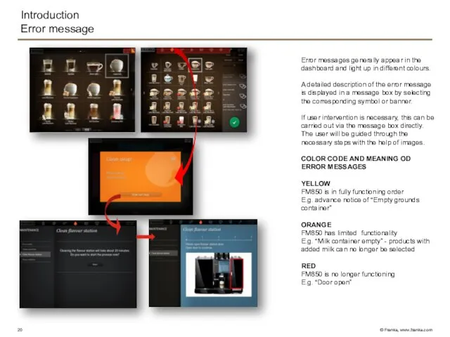
Error messages generally appear in the dashboard and light up in
Error messages generally appear in the dashboard and light up in
43E
One brewing system for single & double shots. For classic Espresso
43E
One brewing system for single & double shots. For classic Espresso
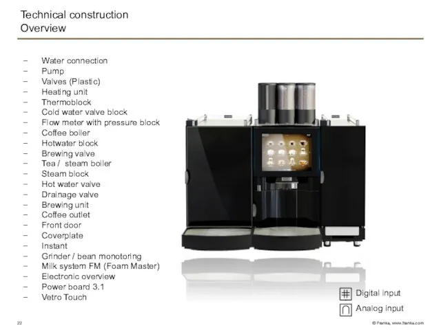
Technical construction
Overview
Water connection
Pump
Valves (Plastic)
Heating unit
Thermoblock
Cold water valve block
Flow meter with pressure
Technical construction
Overview
Water connection
Pump
Valves (Plastic)
Heating unit
Thermoblock
Cold water valve block
Flow meter with pressure
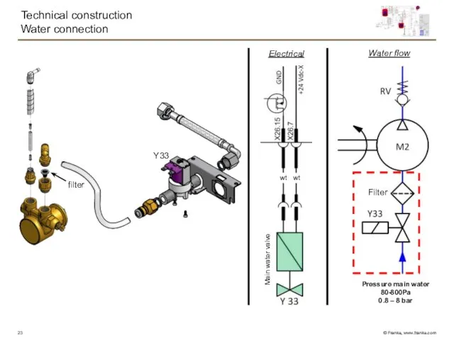
Technical construction
Water connection
Water flow
Y33
Filter
filter
Pressure main water
80-800Pa
0.8 – 8 bar
Electrical
wt
wt
Main water valve
Technical construction
Water connection
Water flow
Y33
Filter
filter
Pressure main water
80-800Pa
0.8 – 8 bar
Electrical
wt
wt
Main water valve
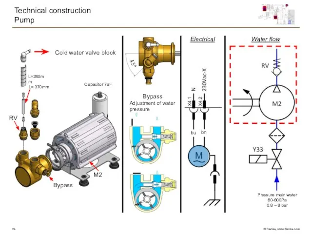
Technical construction
Pump
Water flow
RV
M2
Cold water valve block
Bypass
Bypass
Adjustment of water pressure
Pressure main
Technical construction
Pump
Water flow
RV
M2
Cold water valve block
Bypass
Bypass
Adjustment of water pressure
Pressure main
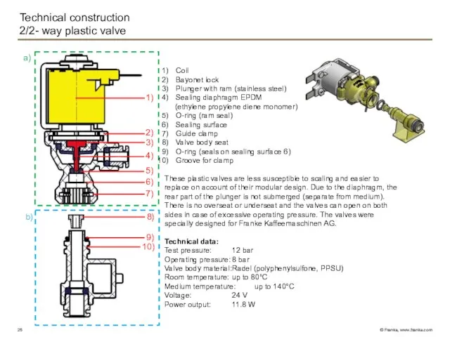
Technical construction
2/2- way plastic valve
1)
2)
3)
4)
6)
5)
7)
9)
10)
a)
b)
8)
Coil
Bayonet lock
Plunger with ram (stainless steel)
Sealing diaphragm
Technical construction
2/2- way plastic valve
1)
2)
3)
4)
6)
5)
7)
9)
10)
a)
b)
8)
Coil
Bayonet lock
Plunger with ram (stainless steel)
Sealing diaphragm
Technical construction
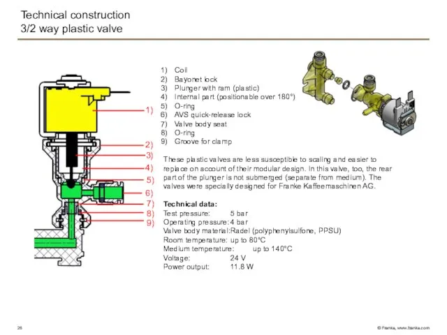
3/2 way plastic valve
1)
2)
3)
4)
6)
5)
7)
8)
9)
Coil
Bayonet lock
Plunger with ram (plastic)
Internal part (positionable
Technical construction
3/2 way plastic valve
1)
2)
3)
4)
6)
5)
7)
8)
9)
Coil
Bayonet lock
Plunger with ram (plastic)
Internal part (positionable
Technical construction
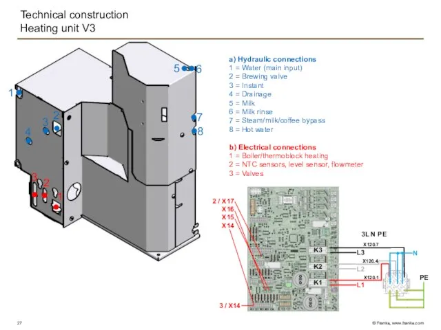
Heating unit V3
2
3
4
1
2
3
6
5
1
7
8
K3
K1
K2
L3
L2
L1
N
PE
X120.7
X120.4
X120.1
3 / X14
2 / X17
X16
X15
X14
a)
Technical construction
Heating unit V3
2
3
4
1
2
3
6
5
1
7
8
K3
K1
K2
L3
L2
L1
N
PE
X120.7
X120.4
X120.1
3 / X14
2 / X17
X16
X15
X14
a)
Technical construction
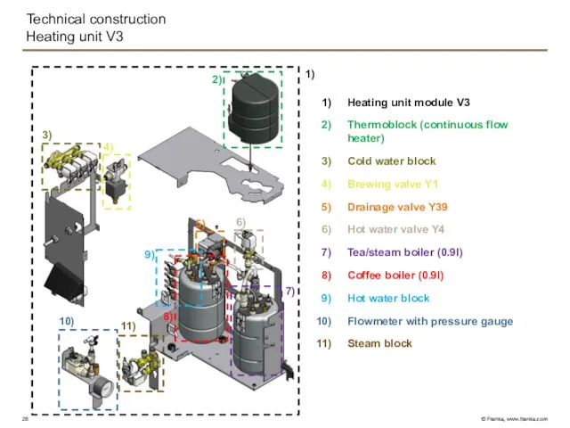
Heating unit V3
1)
2)
3)
4)
5)
6)
7)
8)
9)
10)
11)
Heating unit module V3
Thermoblock (continuous flow heater)
Cold
Technical construction
Heating unit V3
1)
2)
3)
4)
5)
6)
7)
8)
9)
10)
11)
Heating unit module V3
Thermoblock (continuous flow heater)
Cold
Technical construction
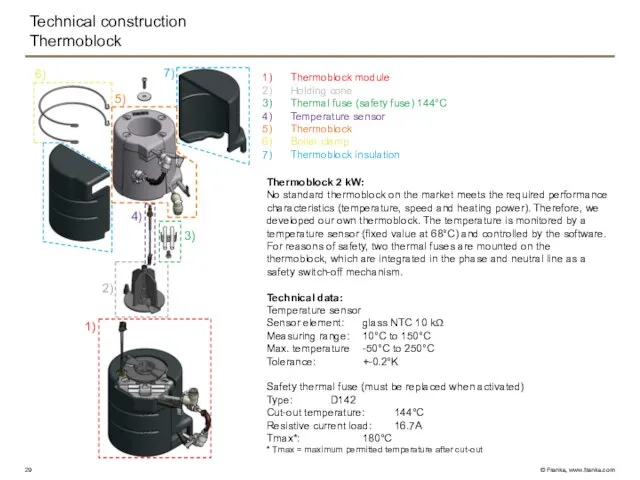
Thermoblock
7)
6)
5)
4)
3)
2)
1)
Thermoblock module
Holding cone
Thermal fuse (safety fuse) 144°C
Temperature sensor
Thermoblock
Boiler clamp
Thermoblock insulation
Thermoblock
Technical construction
Thermoblock
7)
6)
5)
4)
3)
2)
1)
Thermoblock module
Holding cone
Thermal fuse (safety fuse) 144°C
Temperature sensor
Thermoblock
Boiler clamp
Thermoblock insulation
Thermoblock
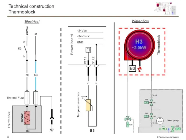
Technical construction
Thermoblock
Water flow
Electrical
230Vac
N
bk
H3
bu
K3
b
a
Thermal Fuse
2000W
GND
+24Vdc-X
+24Vdc
Power board
B3
X17.1
X17.2
vt
vt
Thermoblock
Temperature sensor
Gear pump
Technical construction
Thermoblock
Water flow
Electrical
230Vac
N
bk
H3
bu
K3
b
a
Thermal Fuse
2000W
GND
+24Vdc-X
+24Vdc
Power board
B3
X17.1
X17.2
vt
vt
Thermoblock
Temperature sensor
Gear pump
Technical construction
Cold water valve block
Y30
Y4’
Y5
RV
1)
2)
3)
4)
8)
6)
7)
5)
BK328597 control valve
(adjustable orifice)
Y5:
Function: Tea / steam boiler
Technical construction
Cold water valve block
Y30
Y4’
Y5
RV
1)
2)
3)
4)
8)
6)
7)
5)
BK328597 control valve
(adjustable orifice)
Y5:
Function: Tea / steam boiler
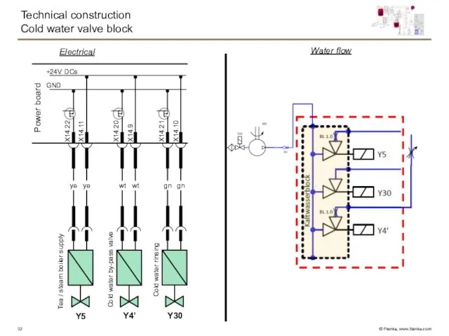
Technical construction
Cold water valve block
GND
+24V DCs
Power board
X14.22
X14.11
X14.20
X14.9
X14.21
X14.10
ye
ye
wt
wt
gn
gn
Y5
Y4’
Y30
Water flow
Electrical
Tea / steam boiler
Technical construction
Cold water valve block
GND
+24V DCs
Power board
X14.22
X14.11
X14.20
X14.9
X14.21
X14.10
ye
ye
wt
wt
gn
gn
Y5
Y4’
Y30
Water flow
Electrical
Tea / steam boiler
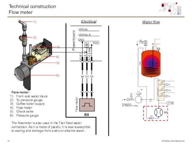
Flow meter:
From cold water block
To pressure gauge
Coffee boiler supply
Flow meter
Check valve
Pressure
Flow meter:
From cold water block
To pressure gauge
Coffee boiler supply
Flow meter
Check valve
Pressure
Technical construction
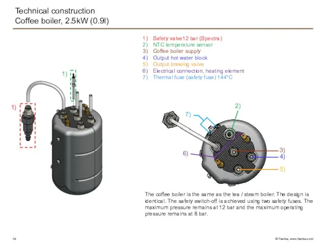
Coffee boiler, 2.5kW (0.9l)
Safety valve12 bar (Spectra)
NTC temperature sensor
Coffee
Technical construction
Coffee boiler, 2.5kW (0.9l)
Safety valve12 bar (Spectra)
NTC temperature sensor
Coffee
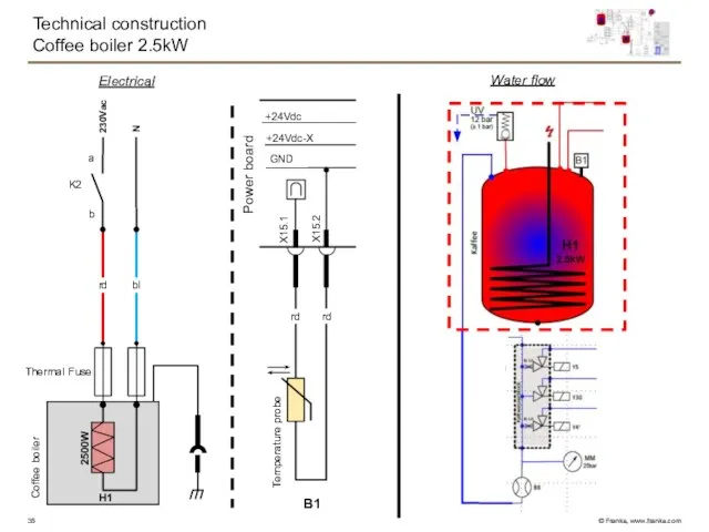
Technical construction
Coffee boiler 2.5kW
Water flow
Electrical
N
rd
H1
bl
K2
b
a
Thermal Fuse
2500W
230Vac
Coffee boiler
GND
+24Vdc-X
+24Vdc
Power board
X15.1
X15.2
rd
rd
Temperature probe
B1
Technical construction
Coffee boiler 2.5kW
Water flow
Electrical
N
rd
H1
bl
K2
b
a
Thermal Fuse
2500W
230Vac
Coffee boiler
GND
+24Vdc-X
+24Vdc
Power board
X15.1
X15.2
rd
rd
Temperature probe
B1
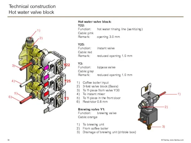
Technical construction
Hot water valve block
Hot water valve block:
Y22:
Function: hot water rinsing line
Technical construction
Hot water valve block
Hot water valve block:
Y22:
Function: hot water rinsing line
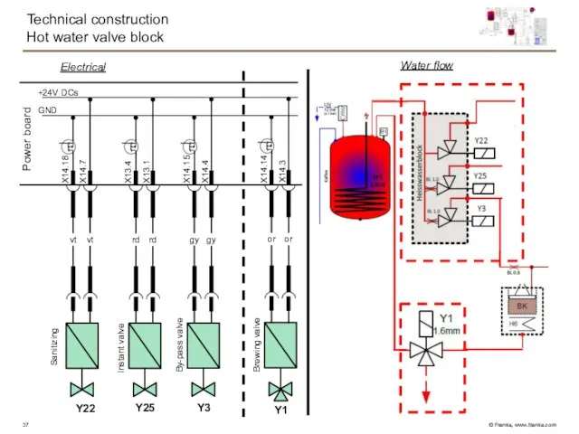
Technical construction
Hot water valve block
GND
+24V DCs
Power board
X14.18
X14.7
X13.4
X13.1
X14.15
X14.4
vt
vt
rd
rd
gy
gy
Y22
Y25
Y3
Water flow
Electrical
Instant valve
By-pass valve
Sanitizing
X14.14
X14.3
or
or
Y1
Brewing valve
Technical construction
Hot water valve block
GND
+24V DCs
Power board
X14.18
X14.7
X13.4
X13.1
X14.15
X14.4
vt
vt
rd
rd
gy
gy
Y22
Y25
Y3
Water flow
Electrical
Instant valve
By-pass valve
Sanitizing
X14.14
X14.3
or
or
Y1
Brewing valve
Technical construction
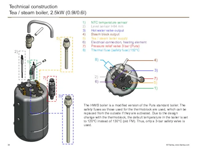
Tea / steam boiler, 2.5kW (0.9l/0.6l)
NTC temperature sensor
Level sensor l=84 mm
Hot
Technical construction
Tea / steam boiler, 2.5kW (0.9l/0.6l)
NTC temperature sensor
Level sensor l=84 mm
Hot
Technical construction
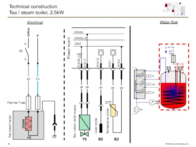
Tea / steam boiler, 2.5kW
Water flow
Electrical
N
gy
H2
bu
K2
b
a
Thermal Fuse
2500W
GND
+24Vdc-X
+24Vdc
Power board
B2
X15.1
X15.2
gy
gy
wt
B5
X14.13
X14.22
X14.11
ye
ye
Y5
230Vac
Tea / steam
Technical construction
Tea / steam boiler, 2.5kW
Water flow
Electrical
N
gy
H2
bu
K2
b
a
Thermal Fuse
2500W
GND
+24Vdc-X
+24Vdc
Power board
B2
X15.1
X15.2
gy
gy
wt
B5
X14.13
X14.22
X14.11
ye
ye
Y5
230Vac
Tea / steam
Technical construction
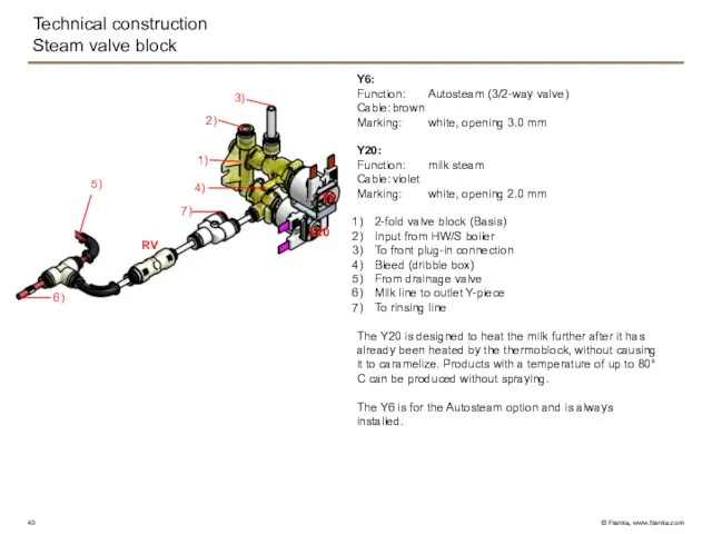
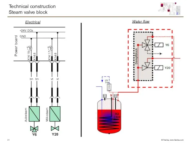
Steam valve block
Y6:
Function: Autosteam (3/2-way valve)
Cable: brown
Marking: white, opening 3.0 mm
Y20:
Function: milk steam
Cable: violet
Marking: white, opening 2.0 mm
2-fold
Technical construction
Steam valve block
Y6:
Function: Autosteam (3/2-way valve)
Cable: brown
Marking: white, opening 3.0 mm
Y20:
Function: milk steam
Cable: violet
Marking: white, opening 2.0 mm
2-fold
Technical construction
Steam valve block
GND
+24V DCs
Power board
X14.19
X14.8
X14.17
X14.6
bn
bn
vt
vt
Y6
Y20
Water flow
Electrical
Autosteam
Milk steam
Technical construction
Steam valve block
GND
+24V DCs
Power board
X14.19
X14.8
X14.17
X14.6
bn
bn
vt
vt
Y6
Y20
Water flow
Electrical
Autosteam
Milk steam
Technical construction
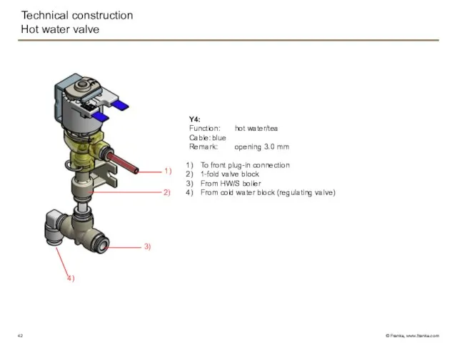
Hot water valve
1)
2)
3)
4)
Y4:
Function: hot water/tea
Cable: blue
Remark: opening 3.0 mm
To front plug-in connection
1-fold valve block
From
Technical construction
Hot water valve
1)
2)
3)
4)
Y4:
Function: hot water/tea
Cable: blue
Remark: opening 3.0 mm
To front plug-in connection
1-fold valve block
From
Technical construction
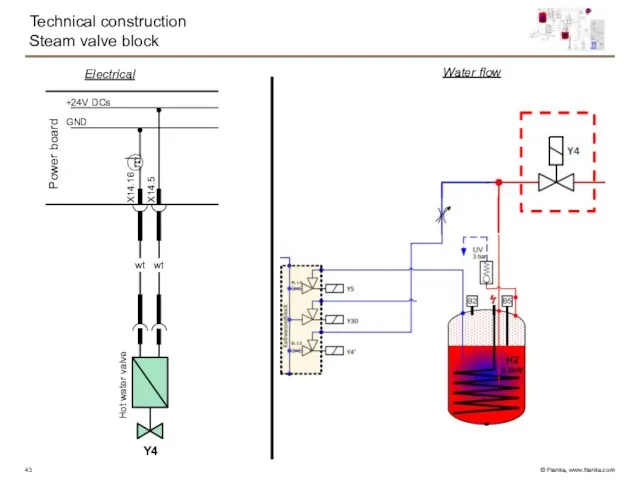
Steam valve block
GND
+24V DCs
Power board
X14.16
X14.5
wt
wt
Y4
Water flow
Electrical
Hot water valve
Technical construction
Steam valve block
GND
+24V DCs
Power board
X14.16
X14.5
wt
wt
Y4
Water flow
Electrical
Hot water valve
Technical construction
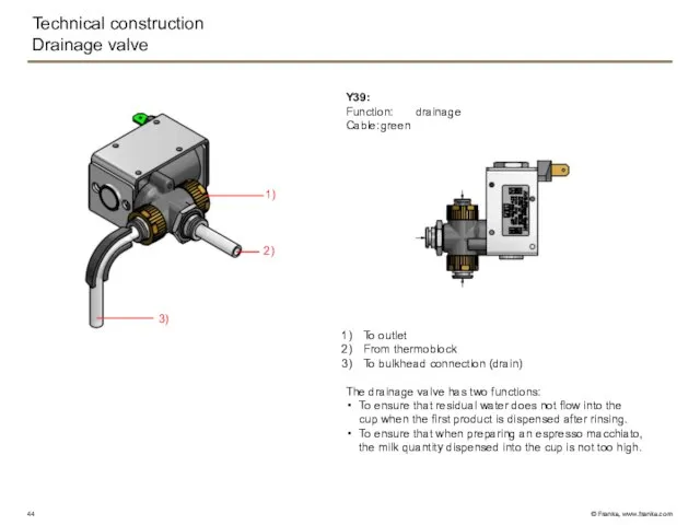
Drainage valve
Y39:
Function: drainage
Cable: green
To outlet
From thermoblock
To bulkhead connection (drain)
The drainage valve has
Technical construction
Drainage valve
Y39:
Function: drainage
Cable: green
To outlet
From thermoblock
To bulkhead connection (drain)
The drainage valve has
Technical construction
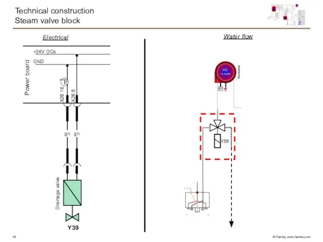
Steam valve block
GND
+24V DCs
Power board
X26.16
X26.8
gn
gn
Y39
Water flow
Electrical
Drainage valve
Technical construction
Steam valve block
GND
+24V DCs
Power board
X26.16
X26.8
gn
gn
Y39
Water flow
Electrical
Drainage valve
Technical construction
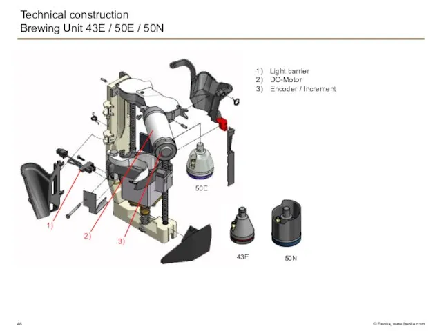
Brewing Unit 43E / 50E / 50N
43E
50E
50N
1)
3)
2)
Light barrier
DC-Motor
Encoder /
Technical construction
Brewing Unit 43E / 50E / 50N
43E
50E
50N
1)
3)
2)
Light barrier
DC-Motor
Encoder /
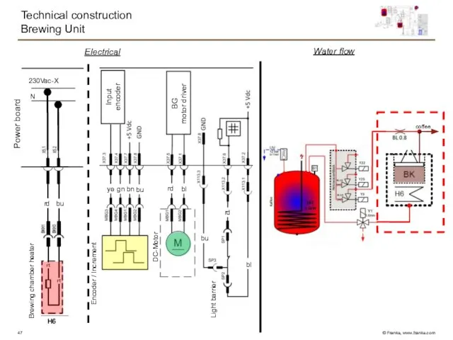
Technical construction
Brewing Unit
Water flow
Electrical
Power board
N
230Vac-X
Brewing chamber heater
Encoder / Increment
DC-Motor
Light barrier
H6
coffee
rd
bu
rd
bl
ye
gn
bn
bu
bl
bu
rd
Technical construction
Brewing Unit
Water flow
Electrical
Power board
N
230Vac-X
Brewing chamber heater
Encoder / Increment
DC-Motor
Light barrier
H6
coffee
rd
bu
rd
bl
ye
gn
bn
bu
bl
bu
rd
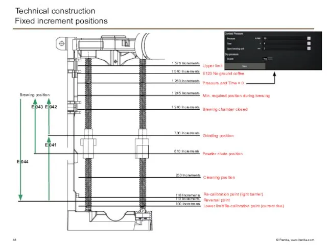
Technical construction
Fixed increment positions
100 Increments
E 042
E 043
E 041
E 044
Lower limit/Re-calibration point
Technical construction
Fixed increment positions
100 Increments
E 042
E 043
E 041
E 044
Lower limit/Re-calibration point
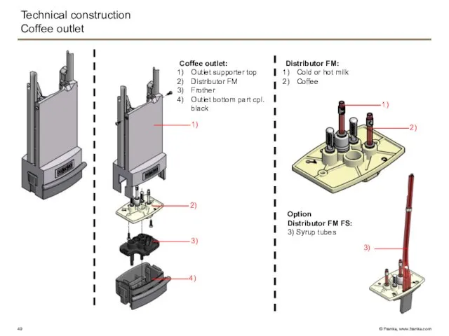
Technical construction
Coffee outlet
Distributor FM:
Cold or hot milk
Coffee
1)
2)
3)
4)
Coffee outlet:
Outlet supporter top
Distributor
Technical construction
Coffee outlet
Distributor FM:
Cold or hot milk
Coffee
1)
2)
3)
4)
Coffee outlet:
Outlet supporter top
Distributor
Technical construction
Front door
Outlet DC-Motor 24VDC
Reed switch
Gear wheel to the outlet
Electrical
Outlet
Motor
GND
+24Vdc-X
+24Vdc
Reed switch
Outlet
Technical construction
Front door
Outlet DC-Motor 24VDC
Reed switch
Gear wheel to the outlet
Electrical
Outlet
Motor
GND
+24Vdc-X
+24Vdc
Reed switch
Outlet
Technical construction
Front door
Front door:
Brewing unit
Bypass
Cold milk
Hot milk
Autosteam (outlet on right)
Hot water
Technical construction
Front door
Front door:
Brewing unit
Bypass
Cold milk
Hot milk
Autosteam (outlet on right)
Hot water
Technical construction
Brewing Unit
Power board
Water flow
Electrical
outlet
coffee
cup
milk
GND
+24V DCs
Valve outlet switch
instant
bn
bn
Technical construction
Brewing Unit
Power board
Water flow
Electrical
outlet
coffee
cup
milk
GND
+24V DCs
Valve outlet switch
instant
bn
bn
Technical construction
Coverplate
1)
2)
3)
4)
Coverplate
Blind lid
Support grinder outside
Support grinder center
Cover cpl. / Cover cpl.
Technical construction
Coverplate
1)
2)
3)
4)
Coverplate
Blind lid
Support grinder outside
Support grinder center
Cover cpl. / Cover cpl.
Technical construction
Instant
Y25
Hot water
1)
2)
3)
4)
5)
7)
8)
6)
Mixing chamber
Whipper motor
Suction cover
Instant fan
Light barrier for powder dosing
Technical construction
Instant
Y25
Hot water
1)
2)
3)
4)
5)
7)
8)
6)
Mixing chamber
Whipper motor
Suction cover
Instant fan
Light barrier for powder dosing
Technical construction
Instant
Electrical
GND
+24Vdc-X
+24Vdc
Instant fan
Valve hot water instant
Quirler motor
Instant right
Instant
Technical construction
Instant
Electrical
GND
+24Vdc-X
+24Vdc
Instant fan
Valve hot water instant
Quirler motor
Instant right
Instant
Technical construction
Grinder / bean monitoring
ceramic
burrs
Grinder specification:
230V 50/60Hz
Capacitor 14uF
Isolation class «F»
Output min.
Technical construction
Grinder / bean monitoring
ceramic
burrs
Grinder specification:
230V 50/60Hz
Capacitor 14uF
Isolation class «F»
Output min.
Technical construction
Milk system FM (Foam Master)
1 Coffee machine, 1 milk
Technical construction
Milk system FM (Foam Master)
1 Coffee machine, 1 milk
Technical construction
Milk slide in module
9) From check valve
Air pulse valve Y42
Technical construction
Milk slide in module
9) From check valve
Air pulse valve Y42
Technical construction
Foam Master PCB
USB
CAN
NTC
Level 1
Level 2
Fuse
24 VDC
Fan
Y42
P1
Y45
Y40
Y38
Y46
Technical construction
Foam Master PCB
USB
CAN
NTC
Level 1
Level 2
Fuse
24 VDC
Fan
Y42
P1
Y45
Y40
Y38
Y46
Technical construction
Gear pump
Construction and functionality
The gear pump is a rotary pump
Technical construction
Gear pump
Construction and functionality
The gear pump is a rotary pump
Technical construction
Air valve
Construction and functionality
The valve plate (sealing element) is directly
Technical construction
Air valve
Construction and functionality
The valve plate (sealing element) is directly
Technical construction
Overview electronic
Switch-mode power supply
Power board (PCB) 3.1
Line Filter
Transformer
Technical construction
Overview electronic
Switch-mode power supply
Power board (PCB) 3.1
Line Filter
Transformer
Technical construction
Power board (PCB) 3.1
Heater coffee/tea_steam1/tea_steam2
Connection neutral line
Connection 208 Vac
Connection 230
Technical construction
Power board (PCB) 3.1
Heater coffee/tea_steam1/tea_steam2
Connection neutral line
Connection 208 Vac
Connection 230
Technical construction
Switch-mode power supply
Power Milk Print
24VDC
Powerboard 3.1 / 24VDC
Power 176-265VAC
Fuse external
Technical construction
Switch-mode power supply
Power Milk Print
24VDC
Powerboard 3.1 / 24VDC
Power 176-265VAC
Fuse external
Technical construction
Operator panel / Vetro Touch
1)
3)
2)
Panel holder guide
Panel connection
Panel
Edge illumination
CPU operator
Technical construction
Operator panel / Vetro Touch
1)
3)
2)
Panel holder guide
Panel connection
Panel
Edge illumination
CPU operator
Technical construction
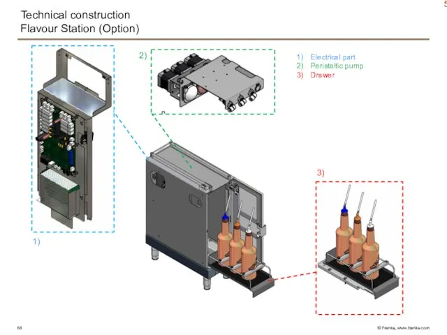
Flavour Station (Option)
5)
Electrical part
Peristaltic pump
Drawer
2)
1)
3)
Technical construction
Flavour Station (Option)
5)
Electrical part
Peristaltic pump
Drawer
2)
1)
3)
Technical construction
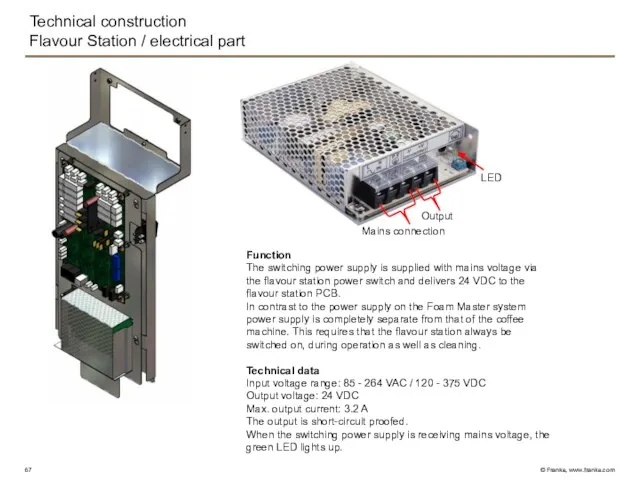
Flavour Station / electrical part
Function
The switching power supply is supplied
Technical construction
Flavour Station / electrical part
Function
The switching power supply is supplied
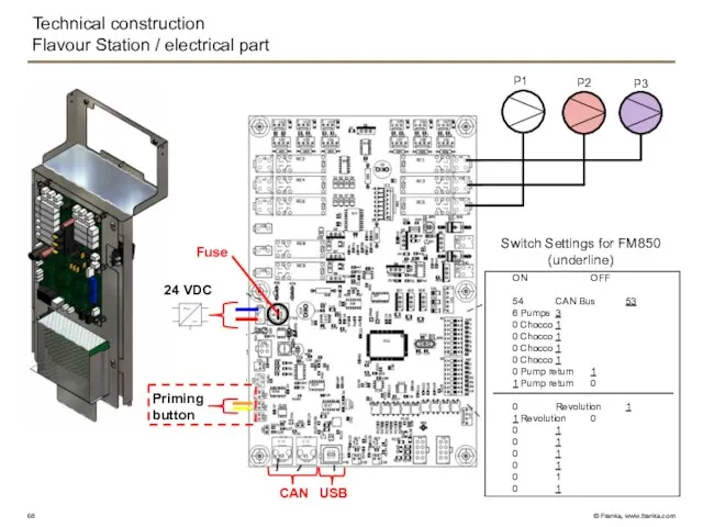
Technical construction
Flavour Station / electrical part
P1
P3
P2
24 VDC
USB
CAN
Priming button
Fuse
ON OFF
54 CAN Bus 53
6 Pumps 3
0 Chocco 1
0 Chocco 1
0 Chocco 1
0 Chocco 1
0 Pump return 1
1 Pump return 0
0
Technical construction
Flavour Station / electrical part
P1
P3
P2
24 VDC
USB
CAN
Priming button
Fuse
ON OFF
54 CAN Bus 53
6 Pumps 3
0 Chocco 1
0 Chocco 1
0 Chocco 1
0 Chocco 1
0 Pump return 1
1 Pump return 0
0
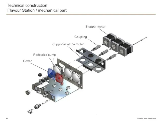
Technical construction
Flavour Station / mechanical part
Stepper motor
Coupling
Supporter of the motor
Peristaltic pump
Cover
Technical construction
Flavour Station / mechanical part
Stepper motor
Coupling
Supporter of the motor
Peristaltic pump
Cover
Technical construction
Flavour Station / Function of the pump
Technical construction
Flavour Station / Function of the pump
Operating
Switch over to the Maintenance level by tipping on the Franke
Operating
Switch over to the Maintenance level by tipping on the Franke
Operating
Operator panel construction
FM850
Operating
Operator panel construction
FM850
Operating
Input methods
Operating
Input methods
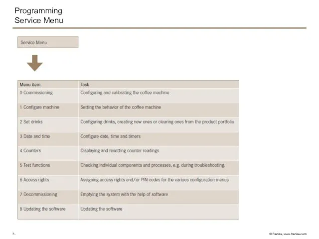
Programming
Service Menu
Programming
Service Menu
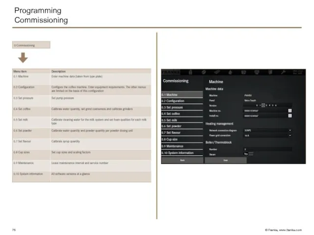
Programming
Commissioning
FM850
Programming
Commissioning
FM850
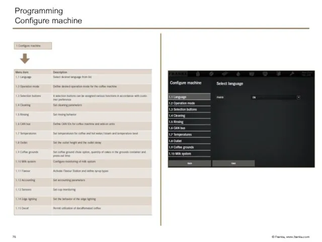
Programming
Configure machine
FM850
Programming
Configure machine
FM850
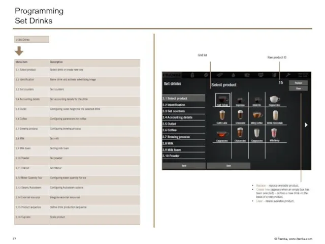
Programming
Set Drinks
Programming
Set Drinks
Programming
Date and Time
Programming
Date and Time
Programming
Test functions
Programming
Test functions
Programming
Access rights
Programming
Access rights
Programming
Decommissioning
Programming
Decommissioning
Programming
Updating the software
Programming
Updating the software
Programming
Individualization and data transfer
Programming
Individualization and data transfer
Programming
Modify depiction
Programming
Modify depiction
Programming
Backing up/loading
All setting in the menu
«0 Commmissioning» is NOT included
Programming
Backing up/loading
All setting in the menu
«0 Commmissioning» is NOT included
Programming
Counters
Programming
Counters
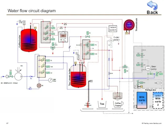
Water flow circuit diagram
Coffee boiler
Outlet switch
Instant
system
Coffee
Cappu
Tea
Tea / steam boiler
Thermoblock
Back
Gear pump
Milk
sorte
1
option
Milk
sorte
2
Refrigerator
Milk
sorte
1
option
Milk
sorte
2
Water flow circuit diagram
Coffee boiler
Outlet switch
Instant
system
Coffee
Cappu
Tea
Tea / steam boiler
Thermoblock
Back
Gear pump
Milk
sorte
1
option
Milk
sorte
2
Refrigerator
Milk
sorte
1
option
Milk
sorte
2
FM850
Commissioning
Product adjustment
Troubleshooting
Cleaning
FM850
Commissioning
Product adjustment
Troubleshooting
Cleaning
 Пешеход на дороге
 20140201_muzykalnaya_azbuka
 Устройство стены, колонны и перекрытия в здании из монолитного железобетона
 Сказочная птица
 Определение в ткани нитей основы и утка
 Виртуальная выставка по страницам периодических изданий посвященная Дню науки и техники Библиотека КМРК
 Восстановление грузовых шин методом холодной варки
 Понятие и элементы социально-психологического климата
 Методика игровой деятельности
 Байкальское общество архитекторов и инженеров
 Электричество
 КФ Интонация
 Заголовок слайда
 Технологія виробництва молока корів
 Поздравление на день рождения
 Религия и мораль. Нравственные заповеди в религиях ислама и буддизма. Урок 26
 Предмет и методы изучения Истории государства и права зарубежных стран
 6. Ребусы 270722
 Технологические процессы заготовительных производств
 Аппаратура защиты и управления напряжением до 1000 В. Лекция №4
 Памятник, детская площадка, музей
 20180113_dm_7_dlina_okruzhnosti_i_ploshchad_kruga
 Расчет эффективности поисков заблудившихся и пропавших без вести в лесной (и не только лесной) местности
 Обзор ограждающих конструкций
 Мир уцелел, потому что смеялся
 Game of Thrones
 Малышам о космосе
 Триггеры в презентации. Применение. Создание слайдов с триггерами