- Instrumentation Amplifier Noise Analysis

Содержание
- 2. Short Review of 3 Amp INA
- 3. Three Stage IA
- 4. Real World Input to Mathematical Model
- 5. Analyze the Input and Output Separately
- 6. Split Input Stage in Half
- 7. Use Superposition on Output Amp
- 8. Gain For Three Amp IA
- 9. Noise Model of 3 Amp INA
- 10. Complex Noise Model
- 11. The Complex Model is Simplified
- 12. The Input amplifier dominates at High Gain
- 13. Taken directly from the graph Calculated using graphs and formula Two Ways to represent INA Spectral
- 14. Hand Analysis of 3 Amp INA
- 15. Find the total RMS Noise Voltage at the Output
- 16. Look at Noise Sources: Bridge, INA333, Reference Buffer
- 17. Noise Equivalent Model for Reference Pin Buffer
- 18. Reference buffer
- 19. The reference voltage directly adds to the output noise
- 20. The bridge generates: thermal noise, in x R_bridge
- 21. Noise From Bridge / Current Sources
- 22. Combine all the noise sources
- 23. Rule of 3x
- 26. Calculate RMS Output Noise for INA333 From Voltage Noise
- 27. Simulation of 3 Amp INA
- 28. Simulate the Circuit
- 29. Using Tina Spice
- 30. Noise Spectral Density at the Output
- 31. Total RMS Noise at the Output
- 32. Bandwidth from Data Sheet and simulated bandwidth is different. The roll-off was approximated as first order
- 33. Reduce Noise Using Averaging Circuit
- 34. Averaging Circuit
- 35. Noise in Averaging Circuit
- 36. Averaging Circuit with INA333
- 37. OPA333 Averaging Circuit 20 INA333 amps in parallel (jumper selectable) Socketed Gain Set Resistors Experiment with
- 38. Linear Power Source Steel Paint Can for Shielding Standard Noise Measurement Precautions
- 39. Total Output Noise vs Number of Amplifiers Being Averaged
- 40. Measured vs simulated spectral density
- 41. [1] Hann, Gina. "Selecting the right op amp - Electronic Products." Electronic Products Magazine – Component
- 43. Скачать презентацию
Short Review of 3 Amp INA
Short Review of 3 Amp INA
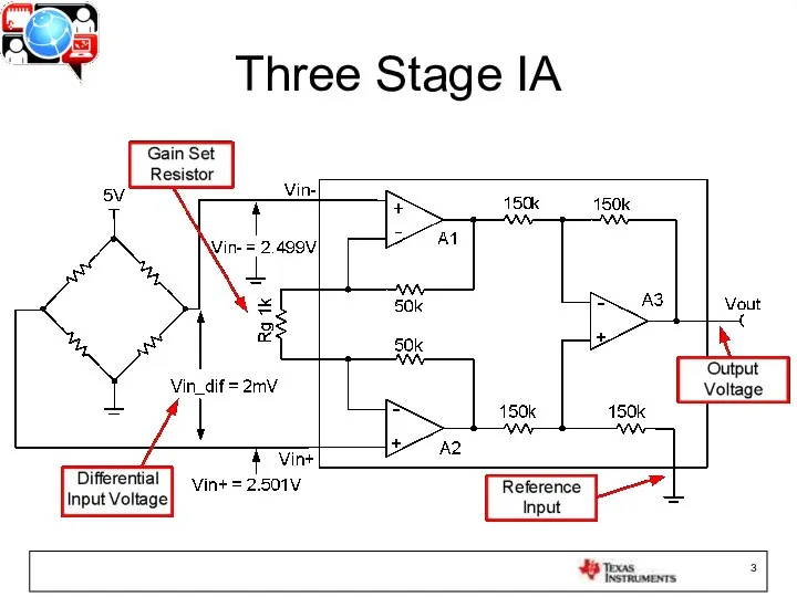
Three Stage IA
Three Stage IA
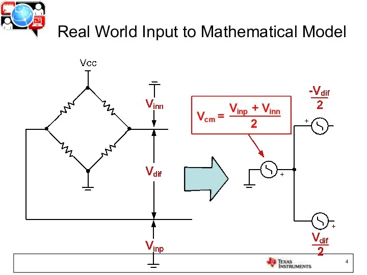
Real World Input to Mathematical Model
Real World Input to Mathematical Model

Analyze the Input and Output Separately
Analyze the Input and Output Separately
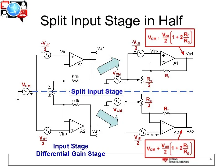
Split Input Stage in Half
Split Input Stage in Half

Use Superposition on Output Amp
Use Superposition on Output Amp
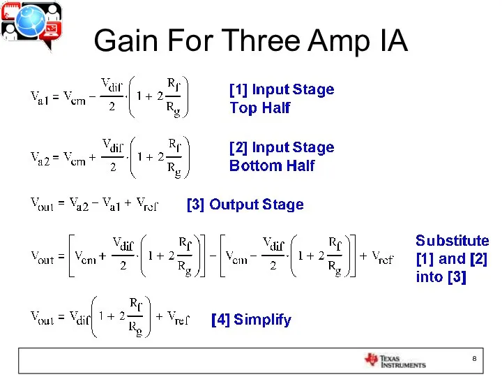
Gain For Three Amp IA
Gain For Three Amp IA

Noise Model of 3 Amp INA
Noise Model of 3 Amp INA
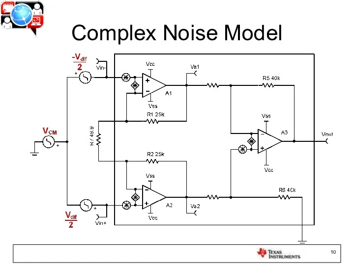
Complex Noise Model
Complex Noise Model

The Complex Model is Simplified
The Complex Model is Simplified
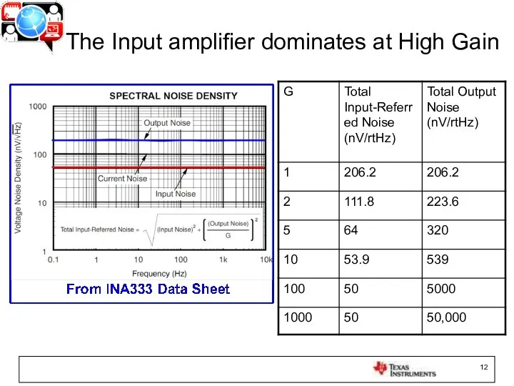
The Input amplifier dominates at High Gain
The Input amplifier dominates at High Gain
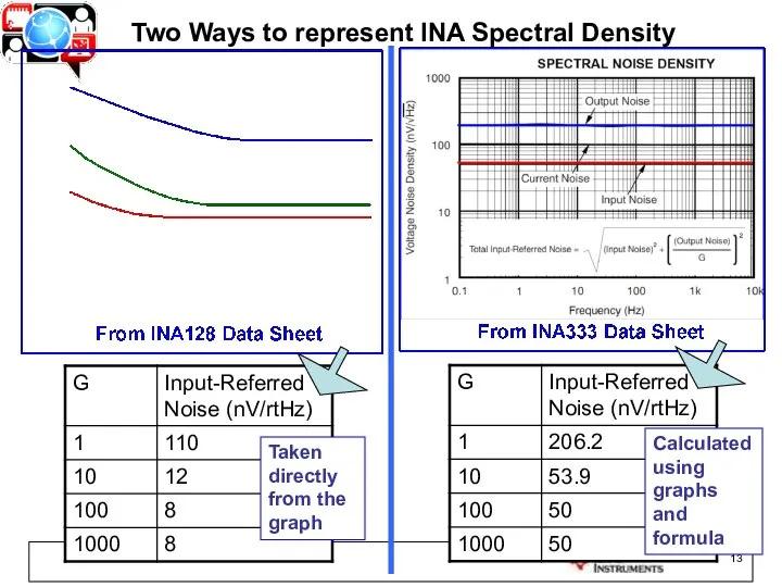
Taken directly from the graph
Calculated using graphs and formula
Two Ways to
Taken directly from the graph
Calculated using graphs and formula
Two Ways to
Hand Analysis of 3 Amp INA
Hand Analysis of 3 Amp INA
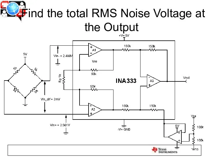
Find the total RMS Noise Voltage at the Output
Find the total RMS Noise Voltage at the Output

Look at Noise Sources:
Bridge, INA333, Reference Buffer
Look at Noise Sources:
Bridge, INA333, Reference Buffer
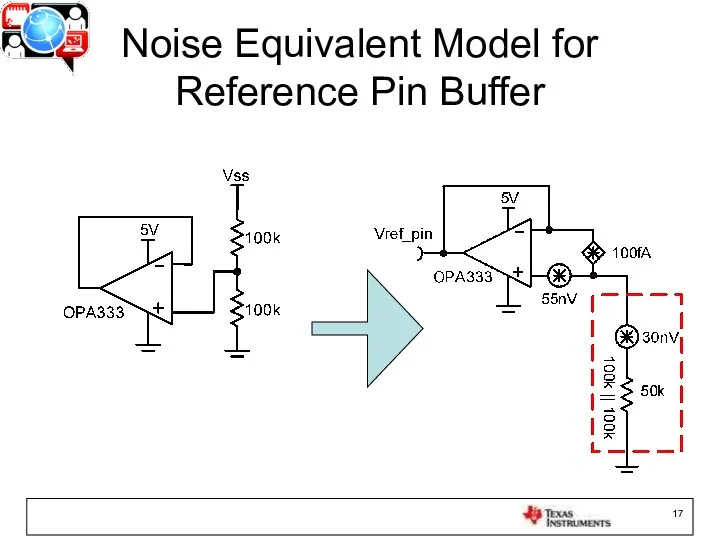
Noise Equivalent Model for Reference Pin Buffer
Noise Equivalent Model for Reference Pin Buffer
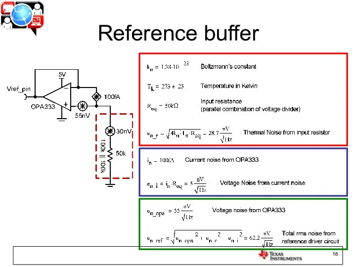
Reference buffer
Reference buffer
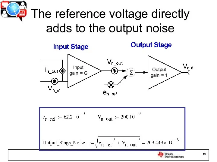
The reference voltage directly adds to the output noise
The reference voltage directly adds to the output noise

The bridge generates:
thermal noise, in x R_bridge
The bridge generates:
thermal noise, in x R_bridge
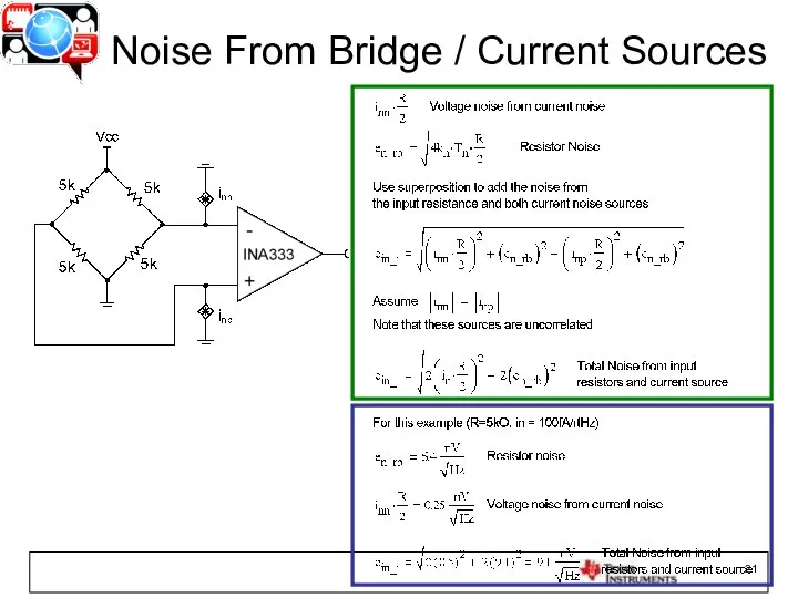
Noise From Bridge / Current Sources
Noise From Bridge / Current Sources
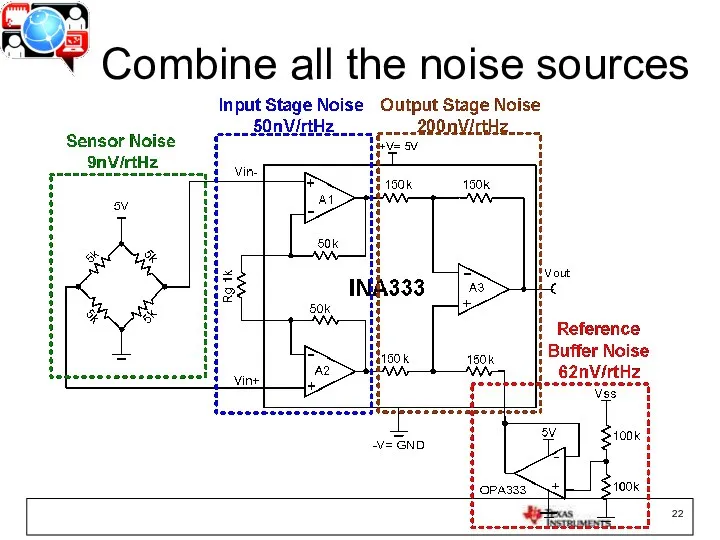
Combine all the noise sources
Combine all the noise sources

Rule of 3x
Rule of 3x


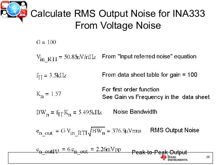
Calculate RMS Output Noise for INA333 From Voltage Noise
Calculate RMS Output Noise for INA333 From Voltage Noise
Simulation of 3 Amp INA
Simulation of 3 Amp INA

Simulate the Circuit
Simulate the Circuit
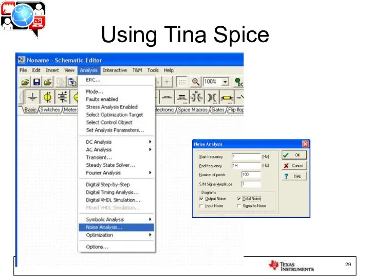
Using Tina Spice
Using Tina Spice
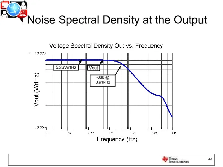
Noise Spectral Density at the Output
Noise Spectral Density at the Output
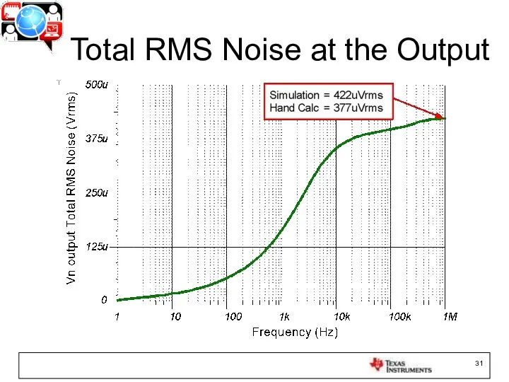
Total RMS Noise at the Output
Total RMS Noise at the Output

Bandwidth from Data Sheet and simulated bandwidth is different.
The roll-off was
Bandwidth from Data Sheet and simulated bandwidth is different.
The roll-off was
Reduce Noise Using Averaging Circuit
Reduce Noise Using Averaging Circuit
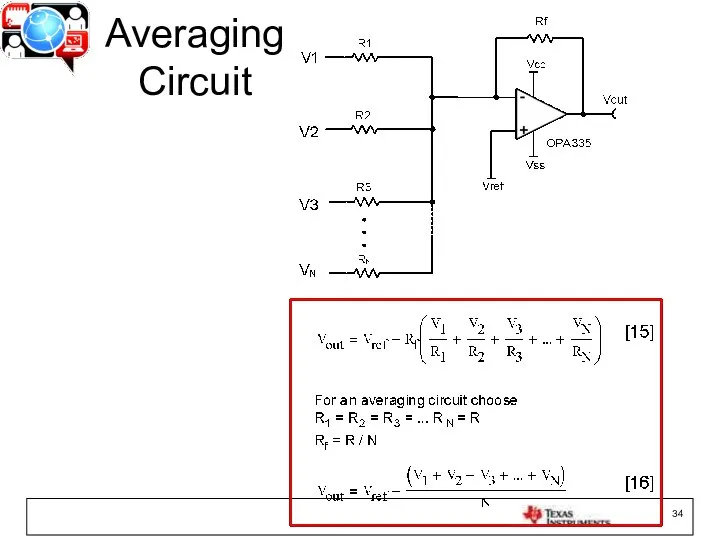
Averaging Circuit
Averaging Circuit
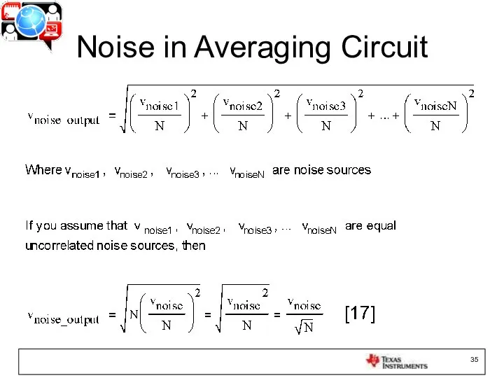
Noise in Averaging Circuit
Noise in Averaging Circuit
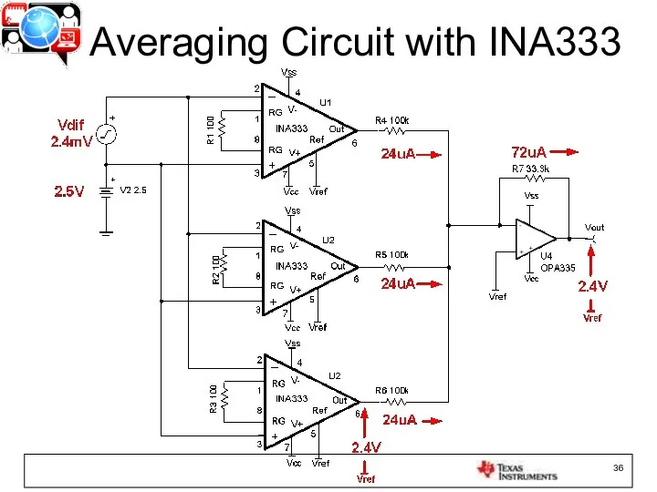
Averaging Circuit with INA333
Averaging Circuit with INA333
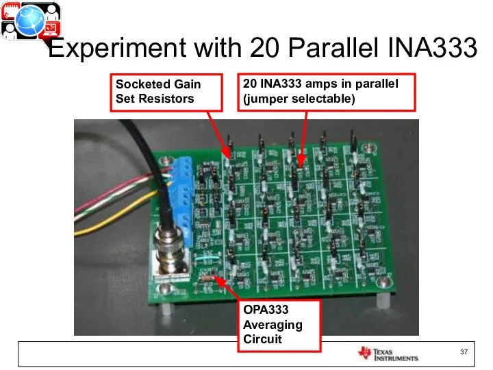
OPA333 Averaging Circuit
20 INA333 amps in parallel (jumper selectable)
Socketed Gain Set
OPA333 Averaging Circuit
20 INA333 amps in parallel (jumper selectable)
Socketed Gain Set

Linear Power Source
Steel Paint Can for Shielding
Standard Noise Measurement Precautions
Linear Power Source
Steel Paint Can for Shielding
Standard Noise Measurement Precautions

Total Output Noise vs Number of Amplifiers Being Averaged
Total Output Noise vs Number of Amplifiers Being Averaged
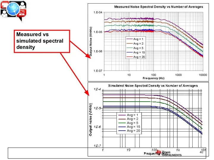
Measured vs simulated spectral density
Measured vs simulated spectral density
![[1] Hann, Gina. "Selecting the right op amp - Electronic Products."](/_ipx/f_webp&q_80&fit_contain&s_1440x1080/imagesDir/jpg/1462970/slide-40.jpg)
[1] Hann, Gina. "Selecting the right op amp - Electronic Products."
[1] Hann, Gina. "Selecting the right op amp - Electronic Products."
 Электрооборудование котельной с разработкой схемы управления резервного источника питания
 О весенней охоте
 ВВЕДЕНИЕ В ТОКСИКОЛОГИЮ
  Организационное проектирование управления персоналом организации на примере ООО «Строительная компания РАЙС-ПРО»
 Устойчивость систем автоматического управления
 Стили в архитектуре Презентация к уроку «Архитектура как отражение миропонимания» в 8 классе.
 Муниципальное общеобразовательное учреждение «Новоквасниковская средняя общеобразовательная школа» Старополтавского района В
 Химически опасные объекты
 Государство как основное звено политической системы
 Повторюємо з Машею вивчені правила. Тренажер
 Искусство Киевской Руси X –XIII вв. 988 г. – крещение Руси князем Владимиром
 DOM Document Object Model - объектная модель документа
 Автор сказки и презентации ИРИНА ВАЖЕНЦЕВА « СКАЗКА О САДОВЫХ ЦВЕТАХ»
  Общие вопросы хирургической инфекции
  Bremen
 Тема урока: Уход за кожей. Гигиена кожи и обуви. Учитель биологии Шевченко О.А. МКОУ Кайгородская СОШ Краснозёрского района Н
 Инвестиционный проект строительства многоквартирного жилого дома с подземным паркингом и ресторанной зоной на 1 этаже
 Что делать, если …. РОДИТЕЛЬСКАЯ ГАЗЕТА
 Однородные члены предложения - презентация для начальной школы
 Знание Ломоносова о языке и искусстве Отчетная работа по элективному курсу «Истории открытий удивительных веществ» Выполнили у
 Презентация Организация: понятие и виды
 Облака – белогривые лошадки Автор: ученица 1 «Б» класса Дараселия Диана Научный руководитель: учитель начальных классов: Галиш
 Ultrasound in Medicine Ультразвук в медицине.
  Дневник прохождения производственной практики в ООО «АНДОР» РГК «УРАРТУ»
 фрактальная геометрия и физика
 ГИГИЕНА ТРУДА В ОКРАСОЧНЫХ ЦЕХАХ
 Презентацию выполнила Учитель начальных классов ГБОУ СОШ НО №388 Козлова Алла Васильевна
 Масленица