- 172 assembling drawing

Содержание
- 2. Product part
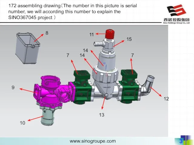
- 3. 10 9 7 13 14 14 15 11 12 8 172 assembling drawing(The number in this
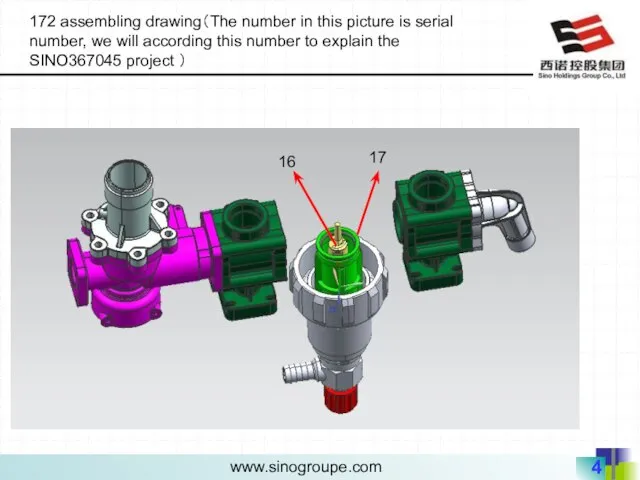
- 4. 16 17 172 assembling drawing(The number in this picture is serial number, we will according this
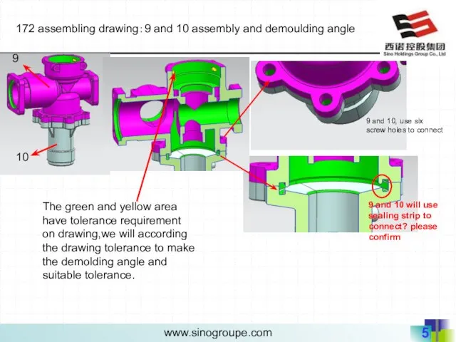
- 5. 172 assembling drawing:9 and 10 assembly and demoulding angle 9 and 10, use six screw holes
- 6. PL mold cavity mold core 172 assembling drawing: 9 and 10 assembly and demoulding angle,parting line
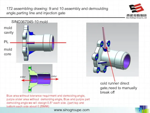
- 7. PL mold cavity mold core 172 assembling drawing: 9 and 10 assembly and demoulding angle,parting line
- 8. 172 assembling drawing: 7 and 9 and 13 assembly and demoulding angle 9 7 7 13
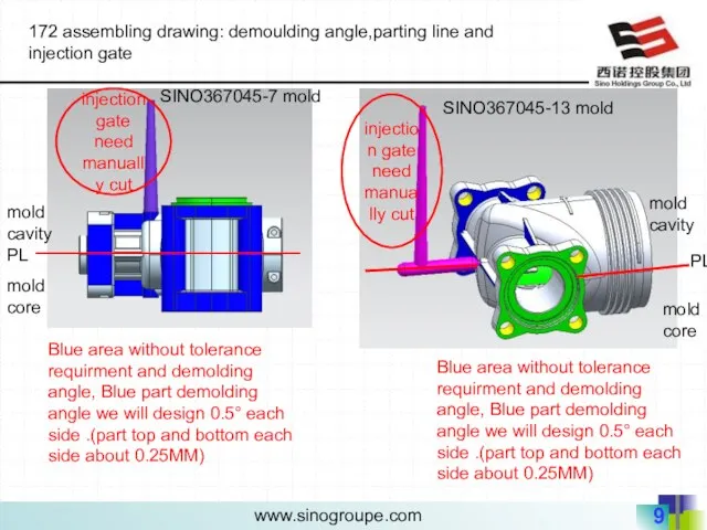
- 9. 172 assembling drawing: demoulding angle,parting line and injection gate PL mold cavity mold core injection gate
- 10. 172 assembling drawing:7and 9 and 13 part question( customer original assembly) ☆:Blue circle assembly is raised(higher),
- 11. 172 assembling drawing:7and 9 and 13 part question(SINO correct assembly) ☆:we think should modify the red
- 12. 172 assembling drawing: 7 and 12 assembly and demoulding angle The green and yellow area have
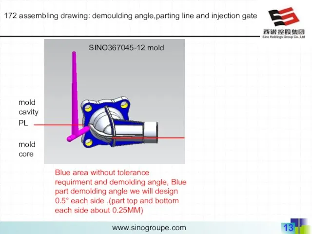
- 13. 172 assembling drawing: demoulding angle,parting line and injection gate PL mold cavity mold core Blue area
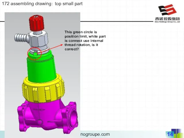
- 14. 172 assembling drawing: top small part This green circle is position limit, white part is connect
- 15. 172 series assembling drawing:small part sealing and assembly comprehend L AL use sealing ring AC use
- 16. 172 series assembling drawing:small part sealing and assembly comprehend L CL use sealing ring EC use
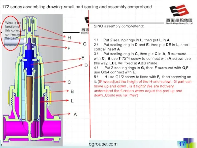
- 17. 172 series assembling drawing:small part sealing and assembly comprehend L SINO assembly comprehend: 1 / Put
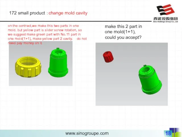
- 18. 172 small product :change mold cavity on the contract,we make this two parts in one mold.
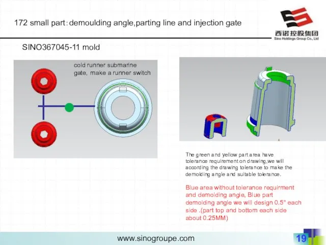
- 19. 172 small part:demoulding angle,parting line and injection gate SINO367045-11 mold cold runner submarine gate,make a runner
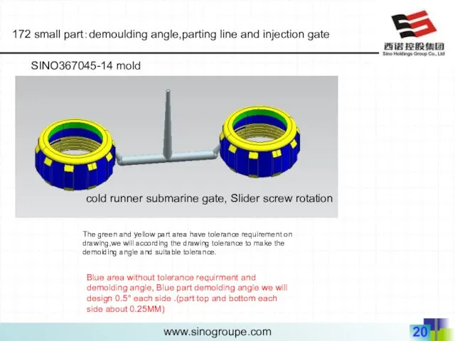
- 20. 172 small part:demoulding angle,parting line and injection gate SINO367045-14 mold Blue area without tolerance requirment and
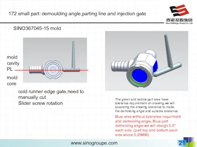
- 21. 172 small part:demoulding angle,parting line and injection gate SINO367045-15 mold Blue area without tolerance requirment and
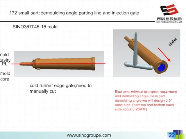
- 22. 172 small part:demoulding angle,parting line and injection gate SINO367045-16 mold Blue area without tolerance requirment and
- 24. Скачать презентацию
Product part
Product part
10
9
7
13
14
14
15
11
12
8
172 assembling drawing(The number in this picture is serial number, we
10
9
7
13
14
14
15
11
12
8
172 assembling drawing(The number in this picture is serial number, we
16
17
172 assembling drawing(The number in this picture is serial number, we
16
17
172 assembling drawing(The number in this picture is serial number, we
172 assembling drawing:9 and 10 assembly and demoulding angle
9 and 10,
172 assembling drawing:9 and 10 assembly and demoulding angle
9 and 10,
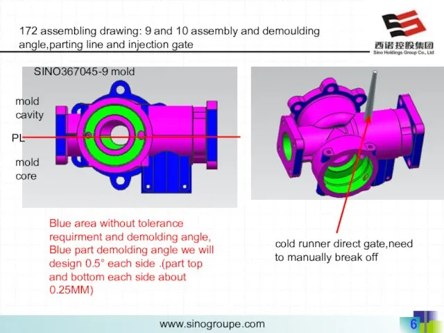
PL
mold cavity
mold core
172 assembling drawing: 9 and 10 assembly and demoulding
PL
mold cavity
mold core
172 assembling drawing: 9 and 10 assembly and demoulding
PL
mold cavity
mold core
172 assembling drawing: 9 and 10 assembly and demoulding
PL
mold cavity
mold core
172 assembling drawing: 9 and 10 assembly and demoulding
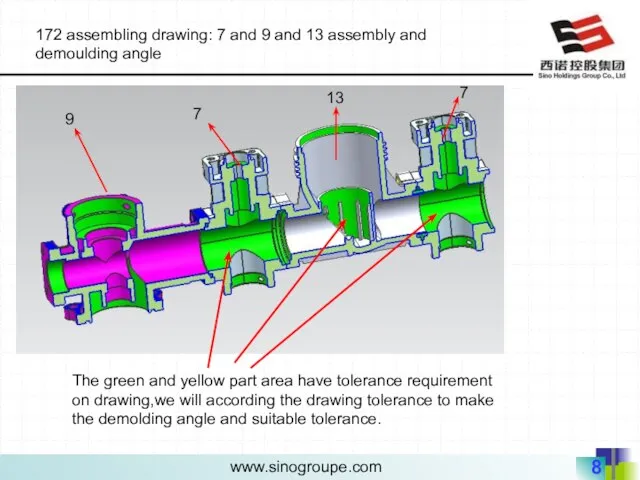
172 assembling drawing: 7 and 9 and 13 assembly and demoulding
172 assembling drawing: 7 and 9 and 13 assembly and demoulding
172 assembling drawing: demoulding angle,parting line and injection gate
PL
mold cavity
mold core
injection
172 assembling drawing: demoulding angle,parting line and injection gate
PL
mold cavity
mold core
injection

172 assembling drawing:7and 9 and 13 part question( customer original
172 assembling drawing:7and 9 and 13 part question( customer original
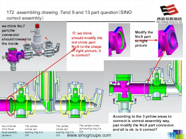
172 assembling drawing:7and 9 and 13 part question(SINO correct assembly)
☆:we think
172 assembling drawing:7and 9 and 13 part question(SINO correct assembly)
☆:we think
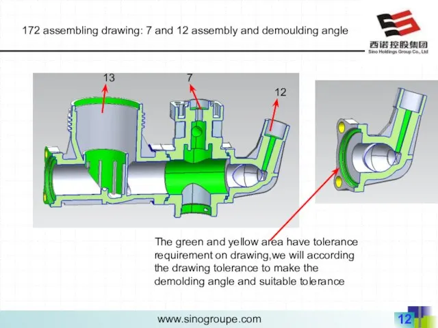
172 assembling drawing: 7 and 12 assembly and demoulding angle
The
172 assembling drawing: 7 and 12 assembly and demoulding angle
The
172 assembling drawing: demoulding angle,parting line and injection gate
PL
mold cavity
mold core
Blue
172 assembling drawing: demoulding angle,parting line and injection gate
PL
mold cavity
mold core
Blue
172 assembling drawing: top small part
This green circle is position limit,
172 assembling drawing: top small part
This green circle is position limit,
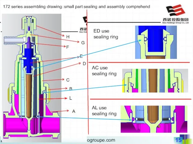
172 series assembling drawing:small part sealing and assembly comprehend
L
AL use
172 series assembling drawing:small part sealing and assembly comprehend
L
AL use

172 series assembling drawing:small part sealing and assembly comprehend
L
CL use sealing
172 series assembling drawing:small part sealing and assembly comprehend
L
CL use sealing
172 series assembling drawing:small part sealing and assembly comprehend
L
SINO assembly comprehend:
1
172 series assembling drawing:small part sealing and assembly comprehend
L
SINO assembly comprehend:
1
172 small product :change mold cavity
on the contract,we make this
172 small product :change mold cavity
on the contract,we make this
172 small part:demoulding angle,parting line and injection gate
SINO367045-11 mold
cold runner submarine
172 small part:demoulding angle,parting line and injection gate
SINO367045-11 mold
cold runner submarine
172 small part:demoulding angle,parting line and injection gate
SINO367045-14 mold
Blue area without
172 small part:demoulding angle,parting line and injection gate
SINO367045-14 mold
Blue area without
172 small part:demoulding angle,parting line and injection gate
SINO367045-15 mold
Blue area without
172 small part:demoulding angle,parting line and injection gate
SINO367045-15 mold
Blue area without
172 small part:demoulding angle,parting line and injection gate
SINO367045-16 mold
Blue area
172 small part:demoulding angle,parting line and injection gate
SINO367045-16 mold
Blue area
 Электромагниттік толқындар
 Построение изображений, даваемых линзами
 Автомобили. Рулевое управление автомобилем и управляемый занос
 Принцип минимума и смена факторов, лимитирующих рост популяции
 Определение прочных размеров деталей рулевого устройства
 Электростатическое поле в вакууме и его характеристики
 Создание платформы для изучения формул по физике
 ИСПОЛЬЗОВАНИЕ ЭЛЕКТРОЭНЕРГИИ В РАЗЛИЧНЫХ ОБЛАСТЯХ НАУКИ И ВЛИЯНИЕ НАУКИ НА ИСПОЛЬЗОВАНИЕ ЭЛЕКТРОЭНЕРГИИ В ЖИЗНИ
  Надпровідність
 Колебания. Общие понятия
 Применение ионизирующего излучения в науке, технике и медицине
 Методы наблюдения и регистрации элементарных частиц
 Технология разборки, ремонта, сборки и регулировки коробки скоростей фрезерного станка
 Основные законы динамики. Принцип Даламбера. Техническая механика
 Теория судна. Статика. Лекция № 1. Геометрия корпуса судна
 Магнитные материалы
 Единицы измерения энергии
 МОУ СОШ №13 Педагог: Васильева М.В. 7 класс 2006 год
 Поверхностное натяжение. Термодинамика жидкостей
 Плоская система сил
 Профессия - ТОРАТ (техническое обслуживание и ремонт автомобильного транспорта)
 Качество электрической энергии
 Размер и форма Земли
 Отражение звука. Эхо. Звуковой резонанс
 Система кондиционирования воздуха
 Баллистическое движение
 Магнитное поле
 Презентация по физике "Физика и методы научного познания" - скачать