- Last Time

Содержание
- 2. 02/21/02 (c) 2001 University of Wisconsin, CS559 Today Viewing Orthographic viewing Homework 3
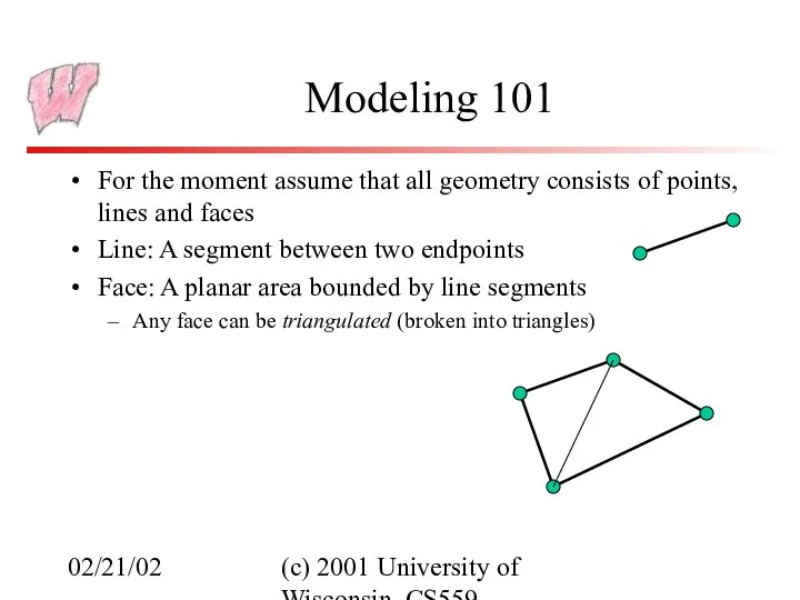
- 3. 02/21/02 (c) 2001 University of Wisconsin, CS559 Modeling 101 For the moment assume that all geometry
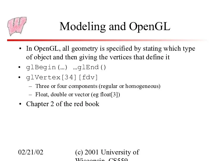
- 4. 02/21/02 (c) 2001 University of Wisconsin, CS559 Modeling and OpenGL In OpenGL, all geometry is specified
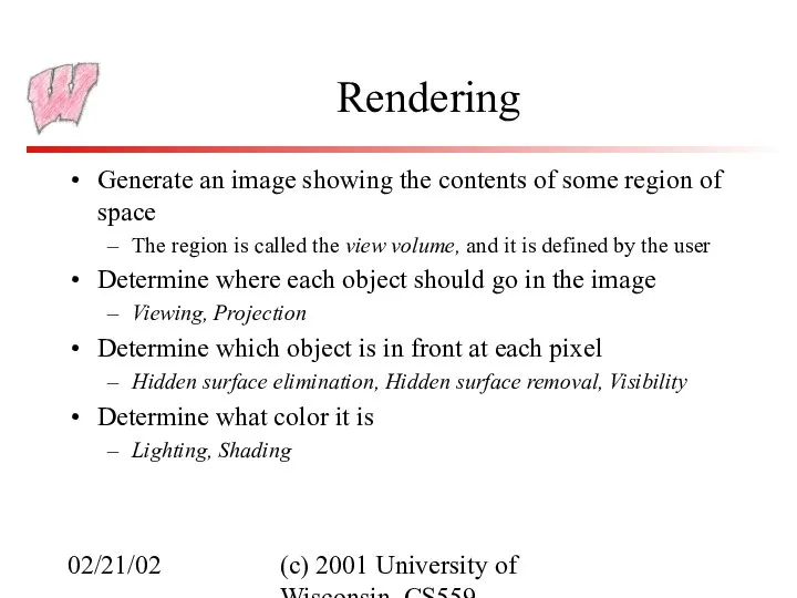
- 5. 02/21/02 (c) 2001 University of Wisconsin, CS559 Rendering Generate an image showing the contents of some
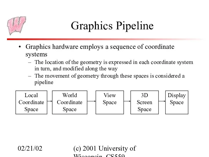
- 6. 02/21/02 (c) 2001 University of Wisconsin, CS559 Graphics Pipeline Graphics hardware employs a sequence of coordinate
- 7. 02/21/02 (c) 2001 University of Wisconsin, CS559 Local Coordinate Space It is easiest to define individual
- 8. 02/21/02 (c) 2001 University of Wisconsin, CS559 Global Coordinate System Everything in the world is transformed
- 9. 02/21/02 (c) 2001 University of Wisconsin, CS559 View Space Associate a set of axes with the
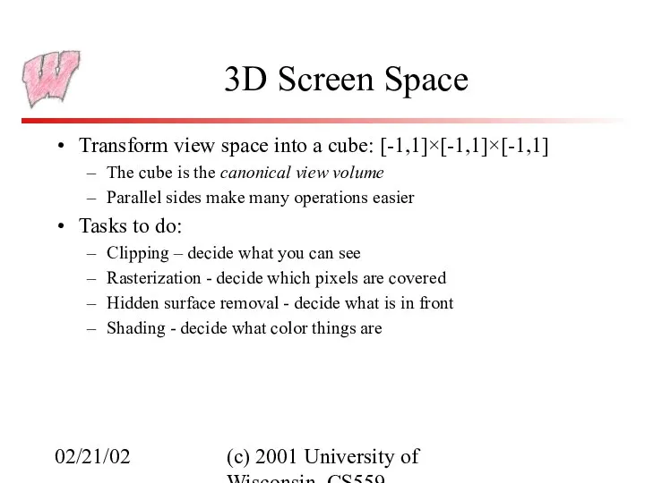
- 10. 02/21/02 (c) 2001 University of Wisconsin, CS559 3D Screen Space Transform view space into a cube:
- 11. 02/21/02 (c) 2001 University of Wisconsin, CS559 Window Space Also called screen space (confusing) Convert the
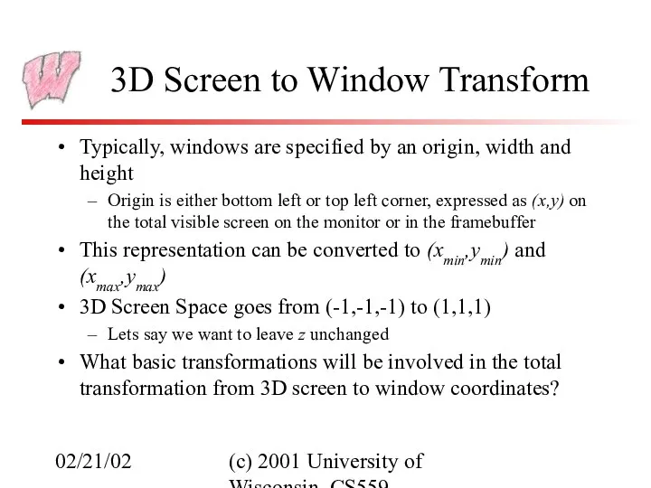
- 12. 02/21/02 (c) 2001 University of Wisconsin, CS559 3D Screen to Window Transform Typically, windows are specified
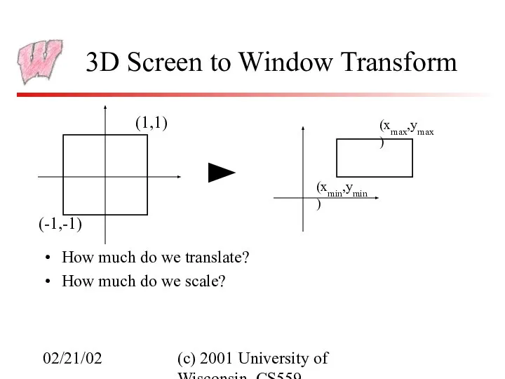
- 13. 02/21/02 (c) 2001 University of Wisconsin, CS559 3D Screen to Window Transform How much do we
- 14. 02/21/02 (c) 2001 University of Wisconsin, CS559 3D Screen to Window Transform (-1,-1) (1,1) (xmin,ymin) (xmax,ymax)
- 15. 02/21/02 (c) 2001 University of Wisconsin, CS559 Orthographic Projection Orthographic projection projects all the points in
- 16. 02/21/02 (c) 2001 University of Wisconsin, CS559 Simple Orthographic Projection Specify the region of space that
- 17. 02/21/02 (c) 2001 University of Wisconsin, CS559 Rendering the Volume To project, map the view volume
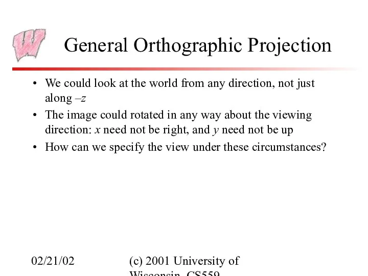
- 18. 02/21/02 (c) 2001 University of Wisconsin, CS559 General Orthographic Projection We could look at the world
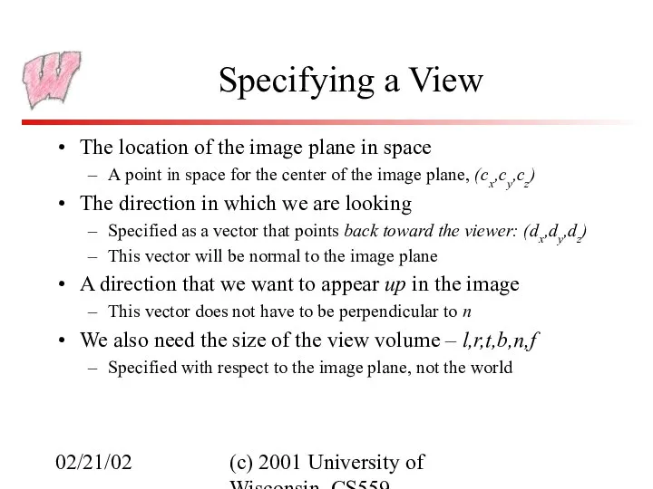
- 19. 02/21/02 (c) 2001 University of Wisconsin, CS559 Specifying a View The location of the image plane
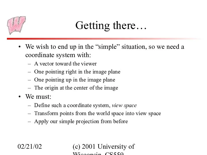
- 20. 02/21/02 (c) 2001 University of Wisconsin, CS559 Getting there… We wish to end up in the
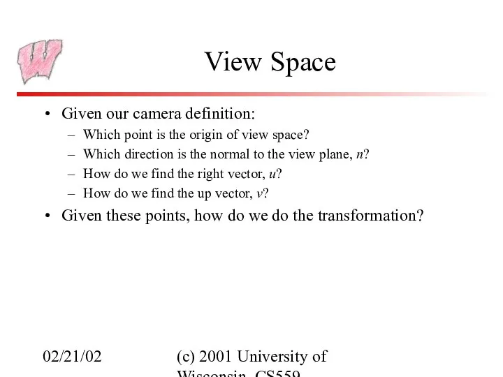
- 21. 02/21/02 (c) 2001 University of Wisconsin, CS559 View Space Given our camera definition: Which point is
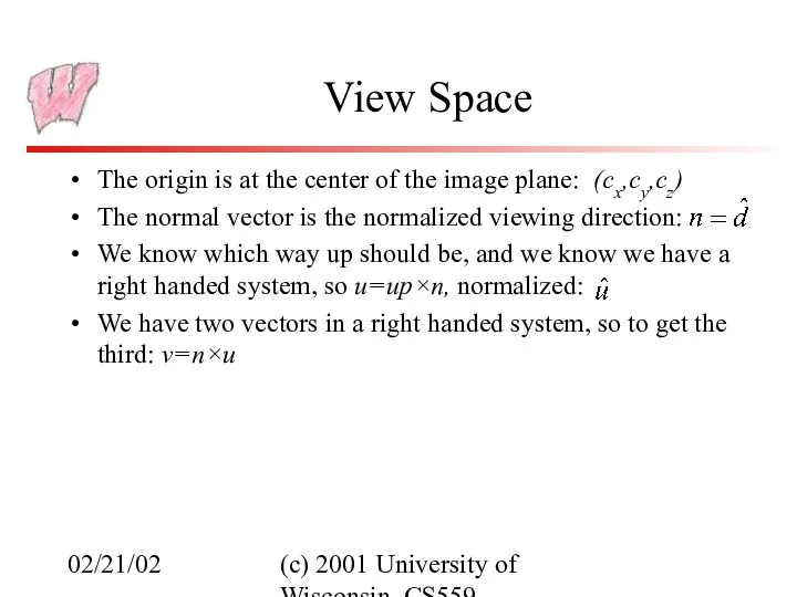
- 22. 02/21/02 (c) 2001 University of Wisconsin, CS559 View Space The origin is at the center of
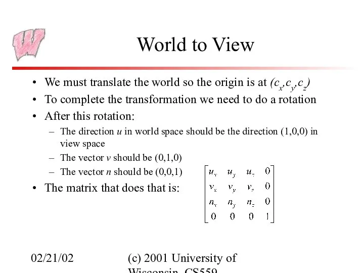
- 23. 02/21/02 (c) 2001 University of Wisconsin, CS559 World to View We must translate the world so
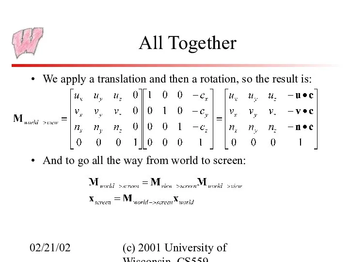
- 24. 02/21/02 (c) 2001 University of Wisconsin, CS559 All Together We apply a translation and then a
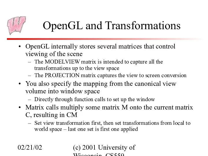
- 25. 02/21/02 (c) 2001 University of Wisconsin, CS559 OpenGL and Transformations OpenGL internally stores several matrices that
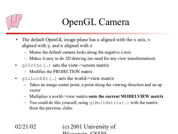
- 26. 02/21/02 (c) 2001 University of Wisconsin, CS559 OpenGL Camera The default OpenGL image plane has u
- 28. Скачать презентацию
02/21/02
(c) 2001 University of Wisconsin, CS559
Today
Viewing
Orthographic viewing
Homework 3
02/21/02
(c) 2001 University of Wisconsin, CS559
Today
Viewing
Orthographic viewing
Homework 3
02/21/02
(c) 2001 University of Wisconsin, CS559
Modeling 101
For the moment assume that
02/21/02
(c) 2001 University of Wisconsin, CS559
Modeling 101
For the moment assume that
02/21/02
(c) 2001 University of Wisconsin, CS559
Modeling and OpenGL
In OpenGL, all geometry
02/21/02
(c) 2001 University of Wisconsin, CS559
Modeling and OpenGL
In OpenGL, all geometry
02/21/02
(c) 2001 University of Wisconsin, CS559
Rendering
Generate an image showing the contents
02/21/02
(c) 2001 University of Wisconsin, CS559
Rendering
Generate an image showing the contents
02/21/02
(c) 2001 University of Wisconsin, CS559
Graphics Pipeline
Graphics hardware employs a sequence
02/21/02
(c) 2001 University of Wisconsin, CS559
Graphics Pipeline
Graphics hardware employs a sequence
02/21/02
(c) 2001 University of Wisconsin, CS559
Local Coordinate Space
It is easiest to
02/21/02
(c) 2001 University of Wisconsin, CS559
Local Coordinate Space
It is easiest to
02/21/02
(c) 2001 University of Wisconsin, CS559
Global Coordinate System
Everything in the world
02/21/02
(c) 2001 University of Wisconsin, CS559
Global Coordinate System
Everything in the world
02/21/02
(c) 2001 University of Wisconsin, CS559
View Space
Associate a set of axes
02/21/02
(c) 2001 University of Wisconsin, CS559
View Space
Associate a set of axes
02/21/02
(c) 2001 University of Wisconsin, CS559
3D Screen Space
Transform view space into
02/21/02
(c) 2001 University of Wisconsin, CS559
3D Screen Space
Transform view space into
02/21/02
(c) 2001 University of Wisconsin, CS559
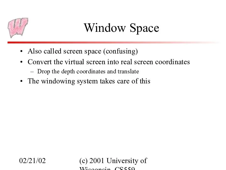
Window Space
Also called screen space (confusing)
Convert
02/21/02
(c) 2001 University of Wisconsin, CS559
Window Space
Also called screen space (confusing)
Convert
02/21/02
(c) 2001 University of Wisconsin, CS559
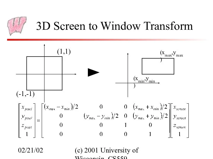
3D Screen to Window Transform
Typically, windows
02/21/02
(c) 2001 University of Wisconsin, CS559
3D Screen to Window Transform
Typically, windows
02/21/02
(c) 2001 University of Wisconsin, CS559
3D Screen to Window Transform
How much
02/21/02
(c) 2001 University of Wisconsin, CS559
3D Screen to Window Transform
How much
02/21/02
(c) 2001 University of Wisconsin, CS559
3D Screen to Window Transform
(-1,-1)
(1,1)
(xmin,ymin)
(xmax,ymax)
02/21/02
(c) 2001 University of Wisconsin, CS559
3D Screen to Window Transform
(-1,-1)
(1,1)
(xmin,ymin)
(xmax,ymax)
02/21/02
(c) 2001 University of Wisconsin, CS559
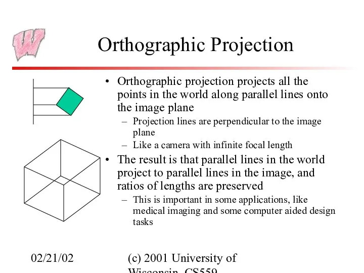
Orthographic Projection
Orthographic projection projects all the
02/21/02
(c) 2001 University of Wisconsin, CS559
Orthographic Projection
Orthographic projection projects all the
02/21/02
(c) 2001 University of Wisconsin, CS559
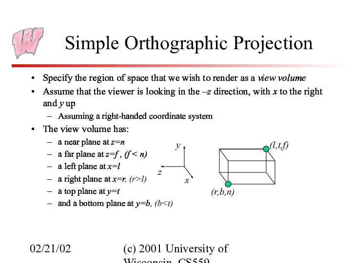
Simple Orthographic Projection
Specify the region of
02/21/02
(c) 2001 University of Wisconsin, CS559
Simple Orthographic Projection
Specify the region of
02/21/02
(c) 2001 University of Wisconsin, CS559
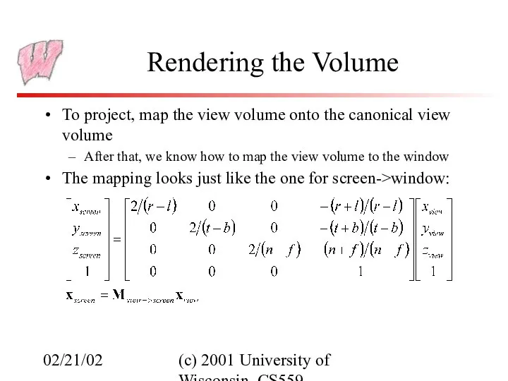
Rendering the Volume
To project, map the
02/21/02
(c) 2001 University of Wisconsin, CS559
Rendering the Volume
To project, map the
02/21/02
(c) 2001 University of Wisconsin, CS559
General Orthographic Projection
We could look at
02/21/02
(c) 2001 University of Wisconsin, CS559
General Orthographic Projection
We could look at
02/21/02
(c) 2001 University of Wisconsin, CS559
Specifying a View
The location of the
02/21/02
(c) 2001 University of Wisconsin, CS559
Specifying a View
The location of the
02/21/02
(c) 2001 University of Wisconsin, CS559
Getting there…
We wish to end up
02/21/02
(c) 2001 University of Wisconsin, CS559
Getting there…
We wish to end up
02/21/02
(c) 2001 University of Wisconsin, CS559
View Space
Given our camera definition:
Which point
02/21/02
(c) 2001 University of Wisconsin, CS559
View Space
Given our camera definition:
Which point
02/21/02
(c) 2001 University of Wisconsin, CS559
View Space
The origin is at the
02/21/02
(c) 2001 University of Wisconsin, CS559
View Space
The origin is at the
02/21/02
(c) 2001 University of Wisconsin, CS559
World to View
We must translate the
02/21/02
(c) 2001 University of Wisconsin, CS559
World to View
We must translate the
02/21/02
(c) 2001 University of Wisconsin, CS559
All Together
We apply a translation and
02/21/02
(c) 2001 University of Wisconsin, CS559
All Together
We apply a translation and
02/21/02
(c) 2001 University of Wisconsin, CS559
OpenGL and Transformations
OpenGL internally stores several
02/21/02
(c) 2001 University of Wisconsin, CS559
OpenGL and Transformations
OpenGL internally stores several
02/21/02
(c) 2001 University of Wisconsin, CS559
OpenGL Camera
The default OpenGL image plane
02/21/02
(c) 2001 University of Wisconsin, CS559
OpenGL Camera
The default OpenGL image plane
 Закон всемирного тяготения
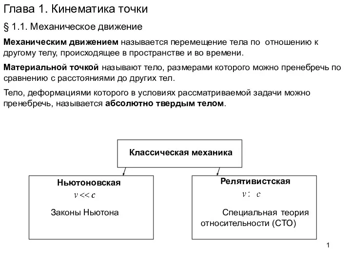 Кинематические точки
 Расчет криволинейных стержней
 Паровая машина Ивана Ползунова
 Законы преломления.
 Нестационарная теплопроводность цилиндра конечных размеров
 Работа и мощность электрического тока
 Электрический ток
 Презентация по физике "Системы цветопередачи" - скачать
  Ритм
Ритм Система с использованием ПИД-регулятора для задачи следования по линии
 Физические основы действия ионизирующего излучения
 Линзы. Виды
 Электромагниты (8 класс)
 Брейн - ринг. Физика
 Двигуни внутрішнього згорання Підготувала учениця 10-Ф класу, Семененко Анна
  Презентация по физике "Динамическая теория дифракции рентгеновских лучей в кристаллах" - скачать бесплатно
 Поперечность световых волн. Поляризация света
 Искровой разряд Презентацию подготовили ученики 9-Б класса ХСШ №16 Поваляев Игорь и Калайтан Владислав
  Потенциальные кривые и условие равновесия механических систем
 Механические колебания и волны. Акустика
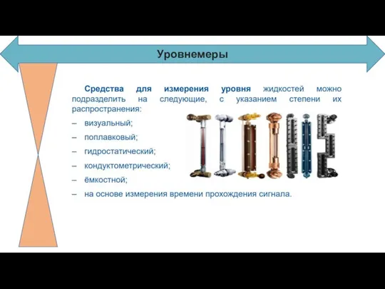 Уровнемеры и датчики положения
 Термодинамическая картина мира
 Неразличимость частиц. Симметрия
 Получение и применение кристаллов
  Проводники и диэлектрики в электростатическом поле
 Атомная физика
 Араластыру әдістері. Пневматикалық араластыру