- Motor classification

Содержание
- 2. reluctance motor – реактивный индукторный двигатель Permanent Magnet Synchronous Motor (PMSM) – вентильный двигатель Brushless Direct
- 3. MOTOR CLASSIFICATION An electric motor is a device which converts electrical energy into kinetic energy (i.e.
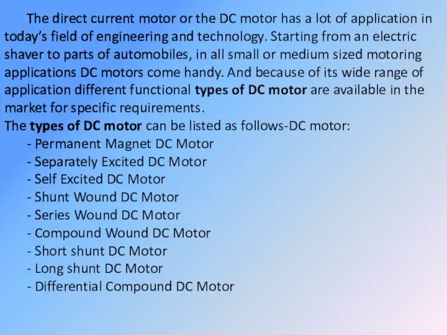
- 5. The direct current motor or the DC motor has a lot of application in today’s field
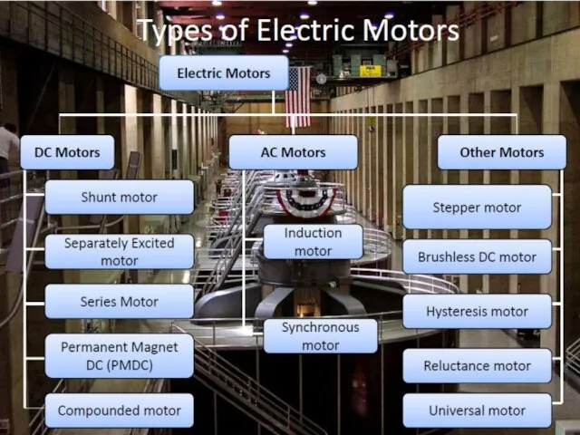
- 6. Types of DC motors
- 7. DC motors are often used in applications where precise speed control is required. They are divided
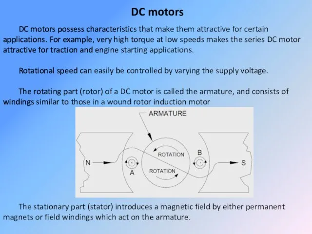
- 8. OPERATING PRINCIPLES a) Major Parts All motors have two basic parts: • The STATOR (stationary part)
- 12. Motor’s Electrical Equations The elevator is driven by a permanent-magnet DC motor. The equivalent circuit of
- 13. The motor voltage equation of the armature circuit is: where: is the electro-motive force developed in
- 14. Mechanical System’s Motion Equations The motion equation of the entire system from the motor’s perspective is:
- 15. The load torque that is placed on the drive pulley which is mounted on the motor’s
- 16. Eqn. 1 was derived for the elevator mechanical system in which the force exerted by the
- 17. This power when written with respect to the pulling belt is: Replacing the belt speed with
- 18. Eqn. 4 and Eqn. 5 hold only when the car is moving upwards and the belt
- 19. Substituting the load torque equation for when the elevator car is moving upwards (Eqn. 6) into
- 20. DC motor modeling
- 21. DC motors DC motors possess characteristics that make them attractive for certain applications. For example, very
- 22. Current flows through the armature windings via carbon brushes and a commutator assembly. The commutator assembly
- 23. This causes the armature to appear as a magnet with which the stator field interacts. The
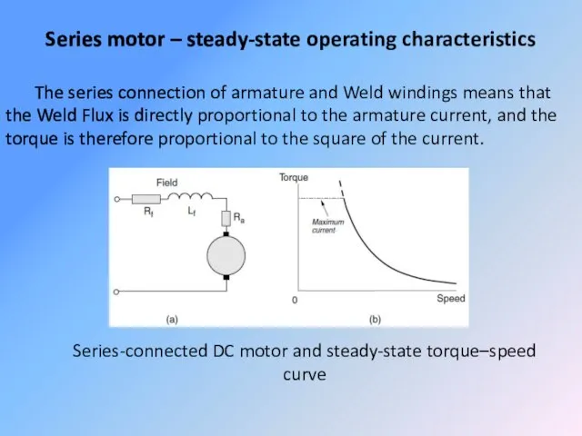
- 24. Series motor – steady-state operating characteristics The series connection of armature and Weld windings means that
- 25. Reversing the direction of the applied voltage (and hence current) therefore leaves the direction of torque
- 26. It is important to note that under normal running conditions the volt drop across the series
- 27. Returning to Figure (b), we note that the series motor differs from most other motors in
- 28. Large series motors have traditionally been used for traction. Often, books say this is because the
- 29. The inherent suitability of the series motor for traction is illustrated by the curves in Figure,
- 30. Some form of speed control is obviously necessary in the example above if the speed of
- 31. This method is inefficient because power is wasted in the resistors, but is simple and cheap
- 32. Four-quadrant operation and regenerative braking The beauty of the separately excited d.c. motor is the ease
- 33. An armature voltage controlled d.c. machine is therefore inherently capable of what is known as ‘four-quadrant’
- 34. Secondly, the supply voltage is shown by the old-fashioned battery symbol, as use of the more
- 35. If, with the motor running at position A, we suddenly reduce the supply voltage to a
- 36. Needless to say the motor will not remain at point B if left to its own
- 37. If we want to operate continuously at position B, the machine will have to be driven
- 38. Separately Excited DC Motor The field (or stator) coil contains a relatively large number of turns
- 39. Excellent speed regulation is characteristic of this design which lends itself well to speed control by
- 40. Compound DC Motor The compound DC motor uses both series and shunt field windings, which are
- 41. Permanent Magnet DC Motors These motors use permanent magnets in place of field windings to establish
- 42. Permanent magnet motors are often used in low horsepower applications, particularly those that are battery operated
- 43. The equations to model the system are:
- 44. Brushed DC Motor In this type of motors, magnetic field is produced by passing current through
- 45. Electronically Commutated Motor (ECM) An ECM is an electronically commutated permanent magnet DC motor (Figure). Electronics
- 46. Although presently more costly than alternative motor technologies, the higher efficiency and flexible operating characteristics of
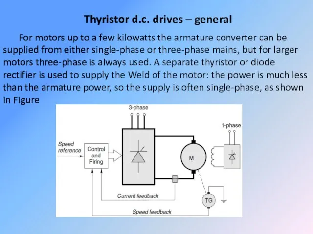
- 47. Thyristor d.c. drives – general For motors up to a few kilowatts the armature converter can
- 48. The arrangement shown in Figure is typical of the majority of d.c. drives and provides for
- 49. Low power control circuits are used to monitor the principal variables of interest (usually motor current
- 50. DC motor, a view inside Simple, cheap. - Easy to control. - 1W - 1kW -
- 51. DC motor control Controller + H-bridge (allows motor to be driven in both directions). Pulse Width
- 52. Speed Control of DC Motors: the speed of a motor is given by the relation It
- 53. Speed Control of Shunt motor: 1. Variation of Flux or Flux Control Method: By decreasing the
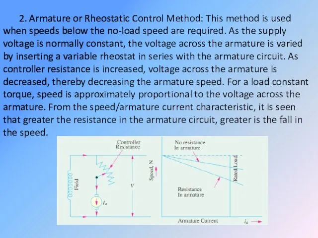
- 54. 2. Armature or Rheostatic Control Method: This method is used when speeds below the no-load speed
- 55. Voltage Control Method: (a) Multiple Voltage Control: In this method, the shunt field of the motor
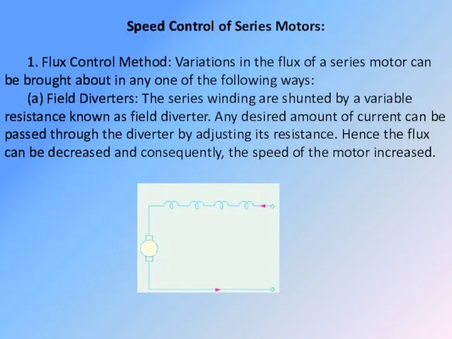
- 56. Speed Control of Series Motors: 1. Flux Control Method: Variations in the flux of a series
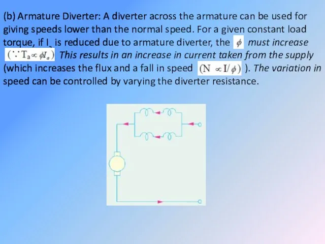
- 57. (b) Armature Diverter: A diverter across the armature can be used for giving speeds lower than
- 58. (c) Trapped Field Control Field: This method is often used in electric traction. The number of
- 59. (d) Paralleling Field coils: this method used for fan motors, several speeds can be obtained by
- 60. 2. Variable Resistance in Series with Motor: By increasing the resistance in series with the armature
- 61. Electric Braking: A motor and its load may be brought to rest quickly by using either
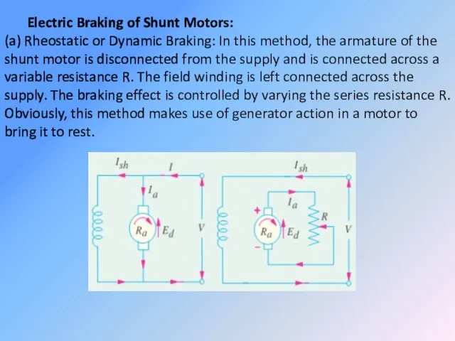
- 62. Electric Braking of Shunt Motors: (a) Rheostatic or Dynamic Braking: In this method, the armature of
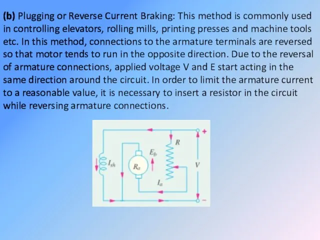
- 63. (b) Plugging or Reverse Current Braking: This method is commonly used in controlling elevators, rolling mills,
- 64. (c) Regenerative Braking: This method is used when the load on the motor has over-hauling characteristic
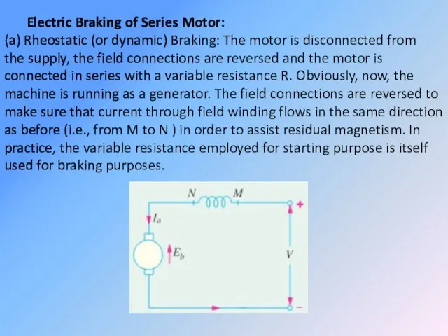
- 65. Electric Braking of Series Motor: (a) Rheostatic (or dynamic) Braking: The motor is disconnected from the
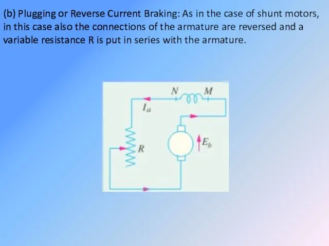
- 66. (b) Plugging or Reverse Current Braking: As in the case of shunt motors, in this case
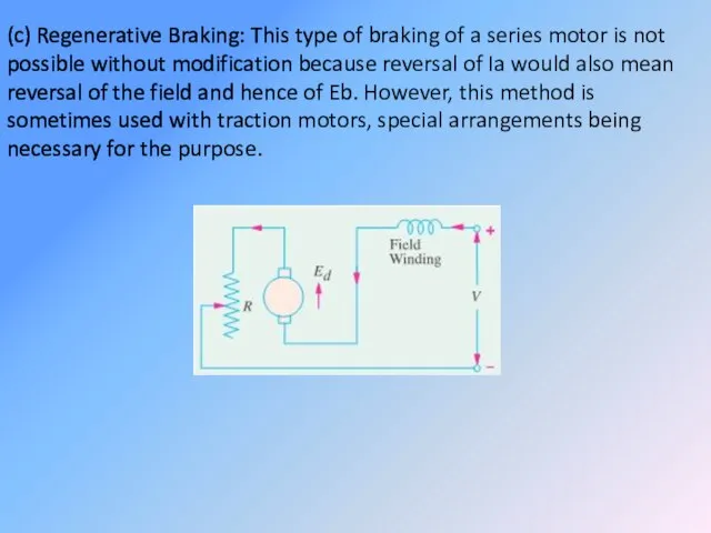
- 67. (c) Regenerative Braking: This type of braking of a series motor is not possible without modification
- 68. Servo motors Although there is no sharp dividing line between servo motors and ordinary motors, the
- 69. The even more arduous condition in which the full armature voltage is suddenly reversed with the
- 70. In the ironless rotor or moving-coil type (Figure 2.14) the armature conductors are formed as a
- 71. Needless to say the absence of slots to support the armature winding results in a relatively
- 72. Early versions were made by using printed-circuit techniques, but pressed fabrication is now more common. Since
- 73. DC servo drives The precise meaning of the term ‘servo’ in the context of motors and
- 74. Motors were therefore developed to meet these exacting requirements, and not surprisingly they were, and still
- 75. The majority of servo drives are sold in modular form, consisting of a high-performance permanent magnet
- 76. Position control As mentioned earlier many servo motors are used in closed-loop position control applications, so
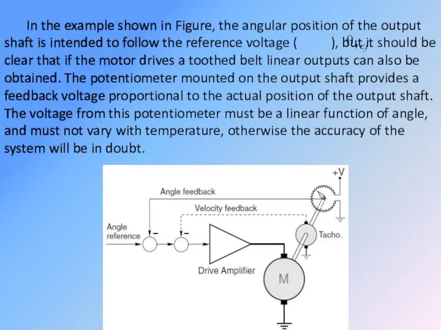
- 77. In the example shown in Figure, the angular position of the output shaft is intended to
- 78. The feedback voltage (representing the actual angle of the shaft) is subtracted from the reference voltage
- 79. The dynamic performance of the simple scheme described above is very unsatisfactory as it stands. In
- 81. Скачать презентацию
reluctance motor – реактивный индукторный двигатель
Permanent Magnet Synchronous Motor (PMSM) –
reluctance motor – реактивный индукторный двигатель
Permanent Magnet Synchronous Motor (PMSM) –
MOTOR CLASSIFICATION
An electric motor is a device which converts electrical energy
MOTOR CLASSIFICATION
An electric motor is a device which converts electrical energy
The direct current motor or the DC motor has a lot of application in today’s
The direct current motor or the DC motor has a lot of application in today’s
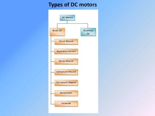
Types of DC motors
Types of DC motors
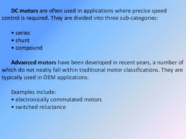
DC motors are often used in applications where precise speed control
DC motors are often used in applications where precise speed control
OPERATING PRINCIPLES
a) Major Parts
All motors have two basic parts:
• The STATOR
OPERATING PRINCIPLES
a) Major Parts
All motors have two basic parts:
• The STATOR


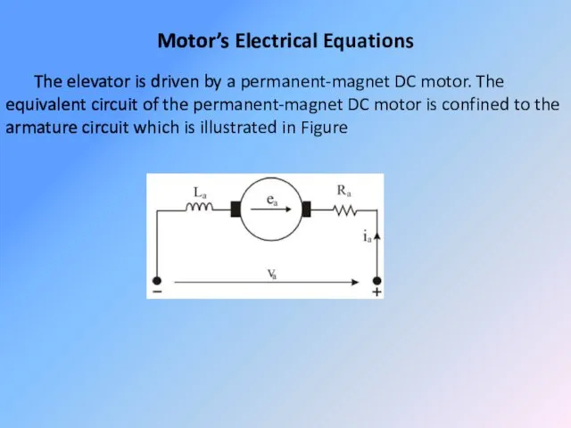
Motor’s Electrical Equations
The elevator is driven by a permanent-magnet DC motor.
Motor’s Electrical Equations
The elevator is driven by a permanent-magnet DC motor.
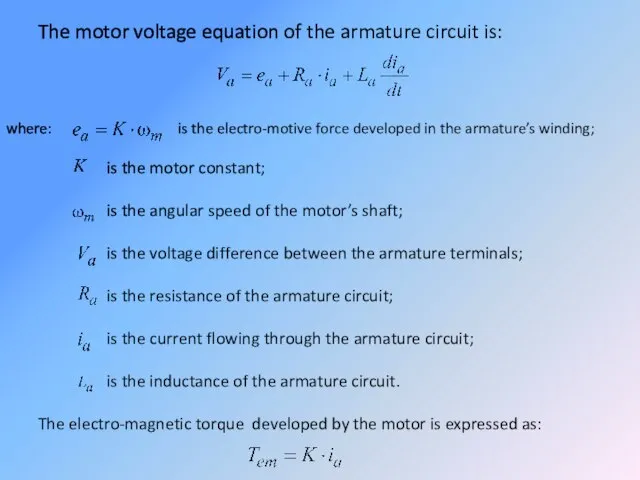
The motor voltage equation of the armature circuit is:
where: is the
The motor voltage equation of the armature circuit is:
where: is the
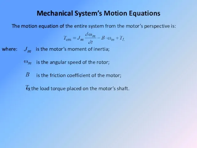
Mechanical System’s Motion Equations
The motion equation of the entire system from
Mechanical System’s Motion Equations
The motion equation of the entire system from
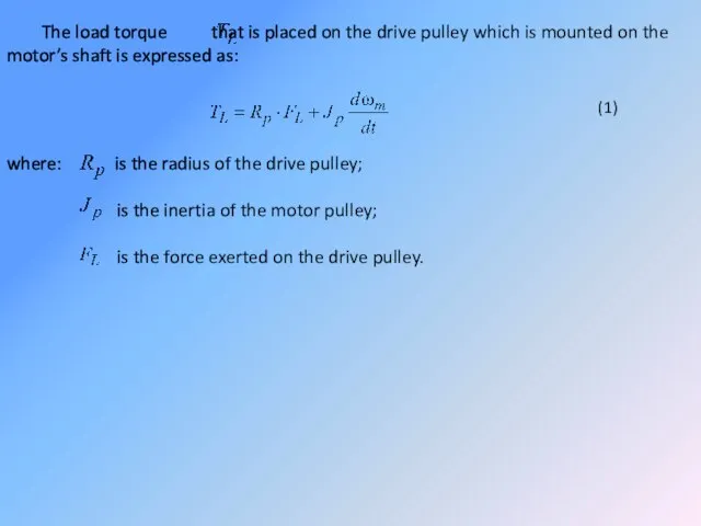
The load torque that is placed on the drive pulley which
The load torque that is placed on the drive pulley which
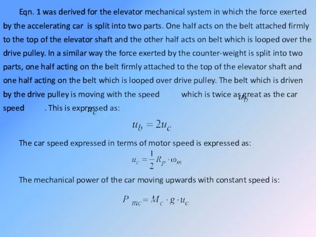
Eqn. 1 was derived for the elevator mechanical system in which
Eqn. 1 was derived for the elevator mechanical system in which
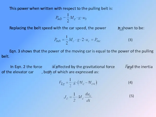
This power when written with respect to the pulling belt is:
Replacing
This power when written with respect to the pulling belt is:
Replacing
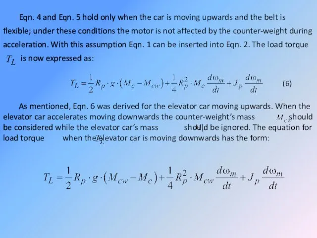
Eqn. 4 and Eqn. 5 hold only when the car is
Eqn. 4 and Eqn. 5 hold only when the car is
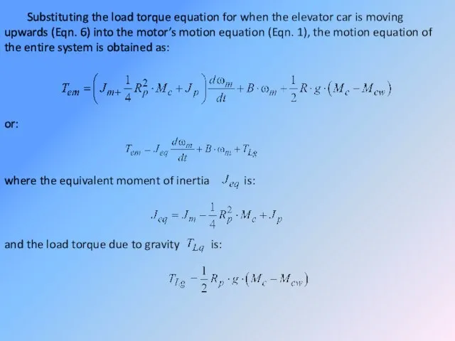
Substituting the load torque equation for when the elevator car is
Substituting the load torque equation for when the elevator car is
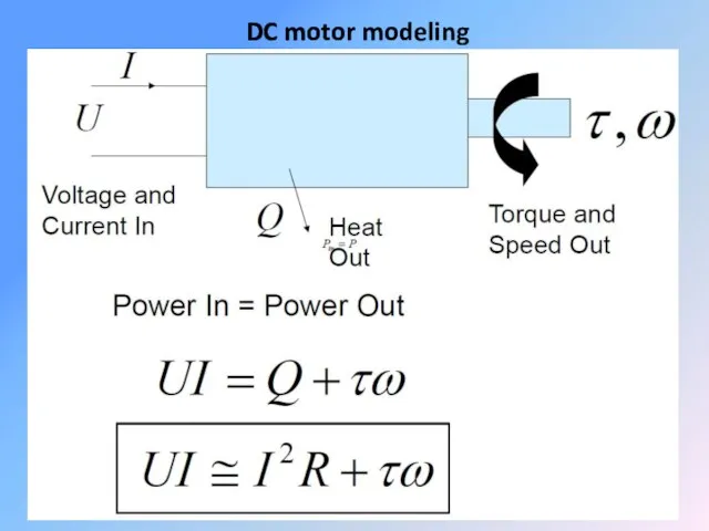
DC motor modeling
DC motor modeling
DC motors
DC motors possess characteristics that make them attractive for certain
DC motors
DC motors possess characteristics that make them attractive for certain
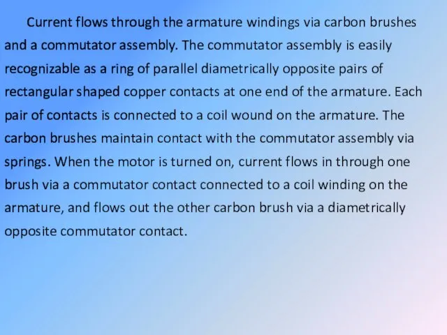
Current flows through the armature windings via carbon brushes and a
Current flows through the armature windings via carbon brushes and a
This causes the armature to appear as a magnet with which
This causes the armature to appear as a magnet with which
Series motor – steady-state operating characteristics
The series connection of armature and
Series motor – steady-state operating characteristics
The series connection of armature and
Reversing the direction of the applied voltage (and hence current) therefore
Reversing the direction of the applied voltage (and hence current) therefore
It is important to note that under normal running conditions the
It is important to note that under normal running conditions the
Returning to Figure (b), we note that the series motor differs
Returning to Figure (b), we note that the series motor differs
Large series motors have traditionally been used for traction. Often, books
Large series motors have traditionally been used for traction. Often, books
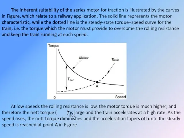
The inherent suitability of the series motor for traction is illustrated
The inherent suitability of the series motor for traction is illustrated
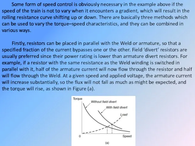
Some form of speed control is obviously necessary in the example
Some form of speed control is obviously necessary in the example

This method is inefficient because power is wasted in the resistors,
This method is inefficient because power is wasted in the resistors,
Four-quadrant operation and regenerative braking
The beauty of the separately excited d.c.
Four-quadrant operation and regenerative braking
The beauty of the separately excited d.c.
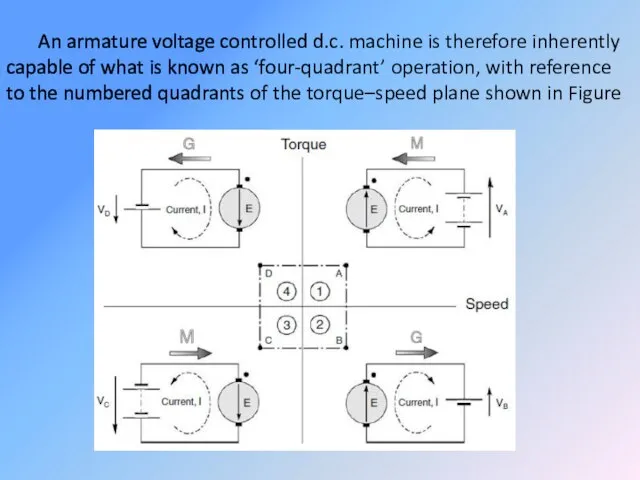
An armature voltage controlled d.c. machine is therefore inherently capable of
An armature voltage controlled d.c. machine is therefore inherently capable of
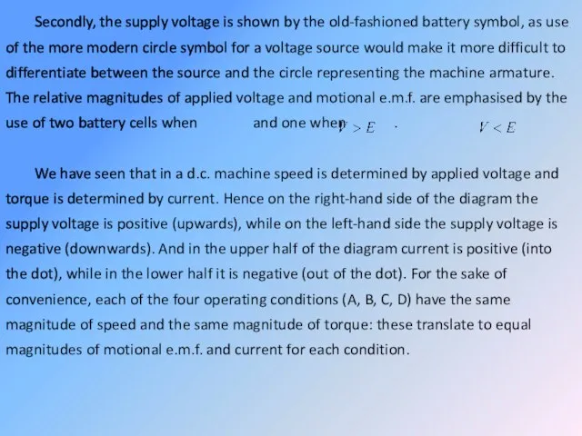
Secondly, the supply voltage is shown by the old-fashioned battery symbol,
Secondly, the supply voltage is shown by the old-fashioned battery symbol,
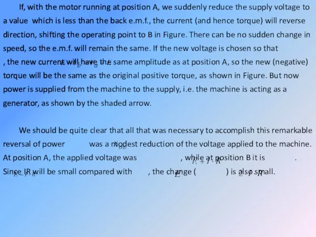
If, with the motor running at position A, we suddenly reduce
If, with the motor running at position A, we suddenly reduce
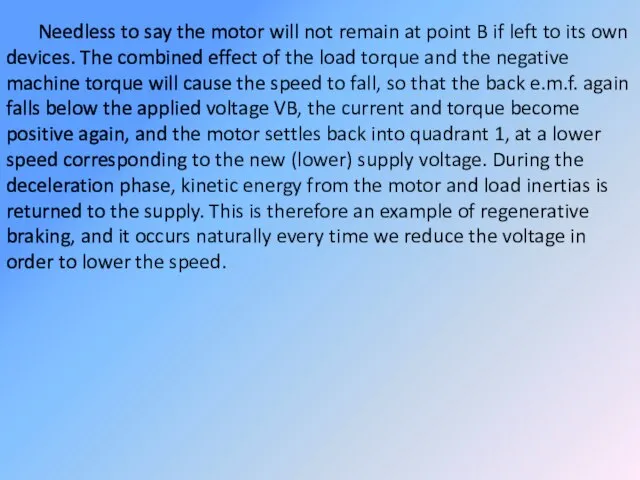
Needless to say the motor will not remain at point B
Needless to say the motor will not remain at point B
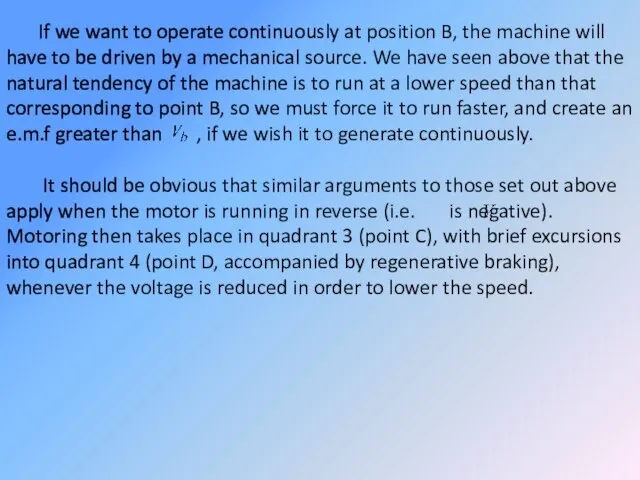
If we want to operate continuously at position B, the machine
If we want to operate continuously at position B, the machine
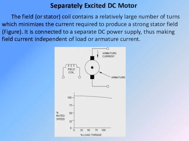
Separately Excited DC Motor
The field (or stator) coil contains a relatively
Separately Excited DC Motor
The field (or stator) coil contains a relatively
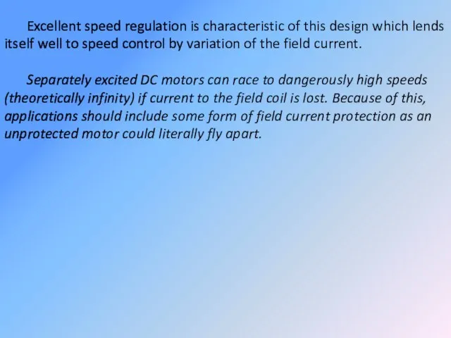
Excellent speed regulation is characteristic of this design which lends itself
Excellent speed regulation is characteristic of this design which lends itself
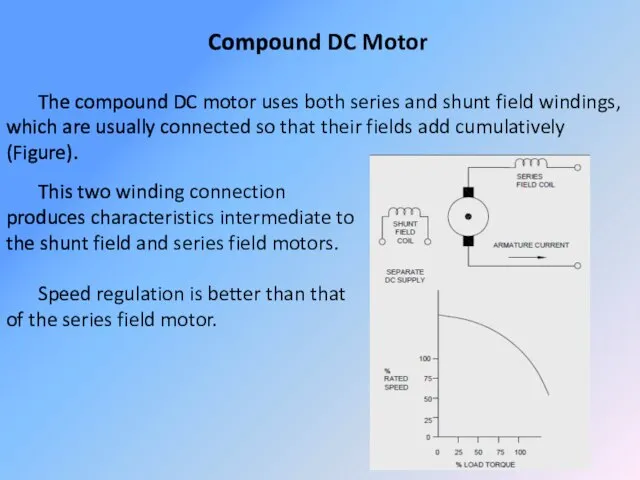
Compound DC Motor
The compound DC motor uses both series and shunt
Compound DC Motor
The compound DC motor uses both series and shunt
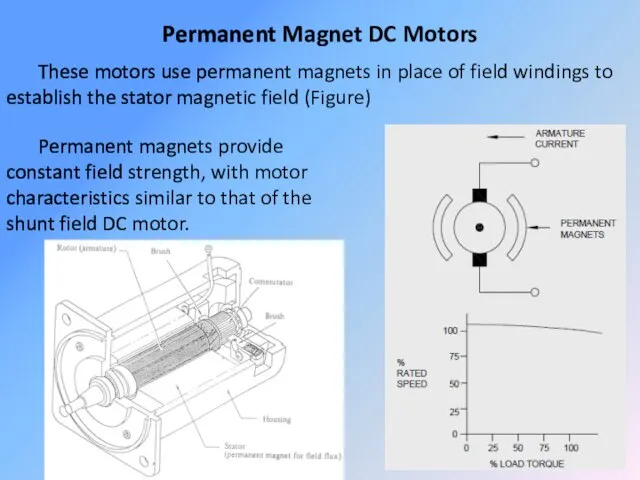
Permanent Magnet DC Motors
These motors use permanent magnets in place of
Permanent Magnet DC Motors
These motors use permanent magnets in place of
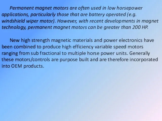
Permanent magnet motors are often used in low horsepower applications, particularly
Permanent magnet motors are often used in low horsepower applications, particularly
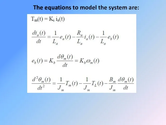
The equations to model the system are:
The equations to model the system are:
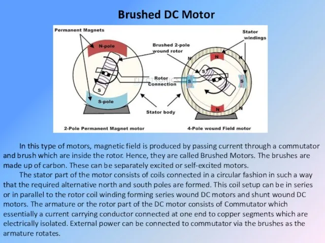
Brushed DC Motor
In this type of motors, magnetic field is produced
Brushed DC Motor
In this type of motors, magnetic field is produced
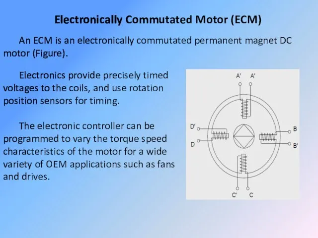
Electronically Commutated Motor (ECM)
An ECM is an electronically commutated permanent magnet
Electronically Commutated Motor (ECM)
An ECM is an electronically commutated permanent magnet
Although presently more costly than alternative motor technologies, the higher efficiency
Although presently more costly than alternative motor technologies, the higher efficiency
Thyristor d.c. drives – general
For motors up to a few kilowatts
Thyristor d.c. drives – general
For motors up to a few kilowatts
The arrangement shown in Figure is typical of the majority of
The arrangement shown in Figure is typical of the majority of
Low power control circuits are used to monitor the principal variables
Low power control circuits are used to monitor the principal variables
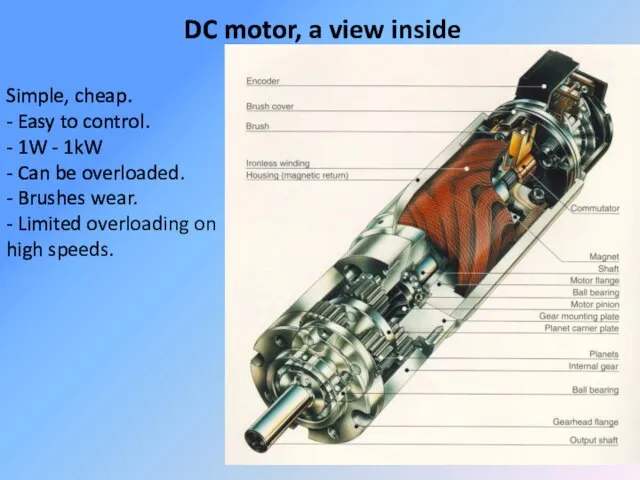
DC motor, a view inside
Simple, cheap.
- Easy to control.
DC motor, a view inside
Simple, cheap.
- Easy to control.
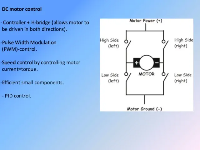
DC motor control
Controller + H-bridge (allows motor to be
DC motor control
Controller + H-bridge (allows motor to be
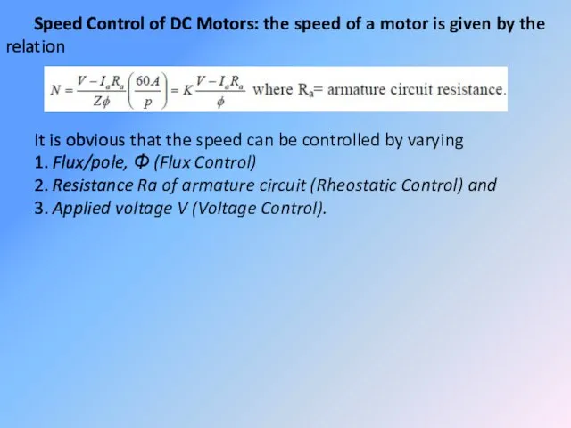
Speed Control of DC Motors: the speed of a motor is
Speed Control of DC Motors: the speed of a motor is
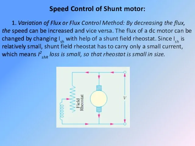
Speed Control of Shunt motor:
1. Variation of Flux or Flux Control
Speed Control of Shunt motor:
1. Variation of Flux or Flux Control
2. Armature or Rheostatic Control Method: This method is used when
2. Armature or Rheostatic Control Method: This method is used when
Voltage Control Method:
(a) Multiple Voltage Control: In this method, the shunt
Voltage Control Method:
(a) Multiple Voltage Control: In this method, the shunt
Speed Control of Series Motors:
1. Flux Control Method: Variations in the
Speed Control of Series Motors:
1. Flux Control Method: Variations in the
(b) Armature Diverter: A diverter across the armature can be used
(b) Armature Diverter: A diverter across the armature can be used
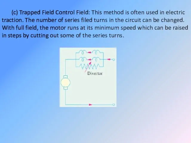
(c) Trapped Field Control Field: This method is often used in
(c) Trapped Field Control Field: This method is often used in
(d) Paralleling Field coils: this method used for fan motors, several
(d) Paralleling Field coils: this method used for fan motors, several
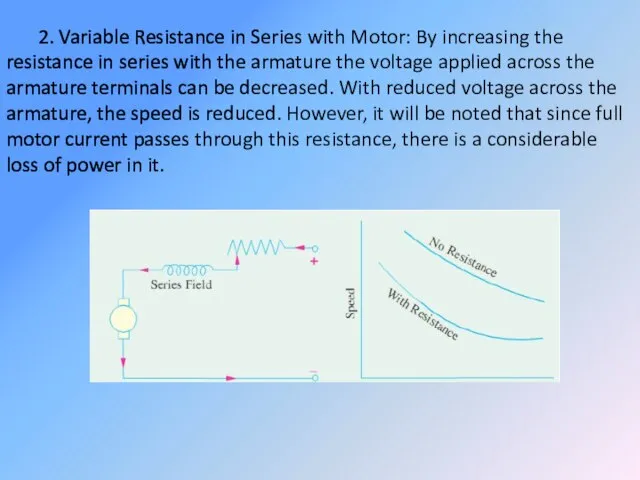
2. Variable Resistance in Series with Motor: By increasing the resistance
2. Variable Resistance in Series with Motor: By increasing the resistance
Electric Braking: A motor and its load may be brought to
Electric Braking: A motor and its load may be brought to
Electric Braking of Shunt Motors:
(a) Rheostatic or Dynamic Braking: In this
Electric Braking of Shunt Motors:
(a) Rheostatic or Dynamic Braking: In this
(b) Plugging or Reverse Current Braking: This method is commonly used
(b) Plugging or Reverse Current Braking: This method is commonly used
(c) Regenerative Braking: This method is used when the load on
(c) Regenerative Braking: This method is used when the load on
Electric Braking of Series Motor:
(a) Rheostatic (or dynamic) Braking: The motor
Electric Braking of Series Motor:
(a) Rheostatic (or dynamic) Braking: The motor
(b) Plugging or Reverse Current Braking: As in the case of
(b) Plugging or Reverse Current Braking: As in the case of
(c) Regenerative Braking: This type of braking of a series motor
(c) Regenerative Braking: This type of braking of a series motor
Servo motors
Although there is no sharp dividing line between servo motors
Servo motors
Although there is no sharp dividing line between servo motors
The even more arduous condition in which the full armature voltage
The even more arduous condition in which the full armature voltage
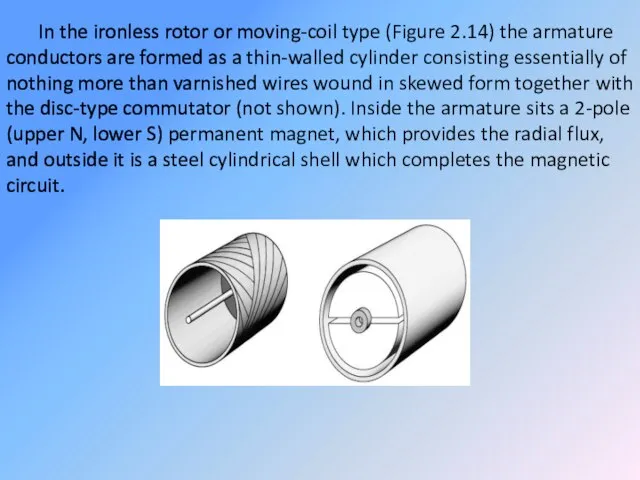
In the ironless rotor or moving-coil type (Figure 2.14) the armature
In the ironless rotor or moving-coil type (Figure 2.14) the armature

Needless to say the absence of slots to support the armature
Needless to say the absence of slots to support the armature
Early versions were made by using printed-circuit techniques, but pressed fabrication
Early versions were made by using printed-circuit techniques, but pressed fabrication

DC servo drives
The precise meaning of the term ‘servo’ in the
DC servo drives
The precise meaning of the term ‘servo’ in the
Motors were therefore developed to meet these exacting requirements, and not
Motors were therefore developed to meet these exacting requirements, and not
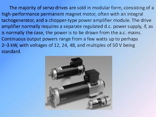
The majority of servo drives are sold in modular form, consisting
The majority of servo drives are sold in modular form, consisting
Position control
As mentioned earlier many servo motors are used in closed-loop
Position control
As mentioned earlier many servo motors are used in closed-loop
In the example shown in Figure, the angular position of the
In the example shown in Figure, the angular position of the
The feedback voltage (representing the actual angle of the shaft) is
The feedback voltage (representing the actual angle of the shaft) is
The dynamic performance of the simple scheme described above is very
The dynamic performance of the simple scheme described above is very
 Дислокации в тонких пленках
 Фонтан Герона
 Уровень планетарной секретности, или операция раскрытия
 Исследование подъёмной силы крыла
 Материалы квантовой и оптоэлектроники. (Лекция 14.6)
 Физико-химические основы горения и взрыва
 Источники света. Распространение света
 Газонаполненные фотоэлементы
 Закон Всемирного тяготения
 Отражение в школьном учебнике физики современных представлений о содержании общего образования
 Роботизированные машины для выполнения интеллектуальных технологий в растениеводстве
 Электропитание устройств и систем телекоммуникаций.
 Уникальные свойства воды
 Продольные и поперечные волны. Уравнение плоской гармонической волны. Стоячие волны
 Спектроскопия электронного парамагнитного резонанса
 Быстрое преобразование Фурье. (Лекция 12)
 Тест по теме «РАБОТА. МОЩНОСТЬ»
 Презентация по физике "Плавление и кристаллизация" - скачать
 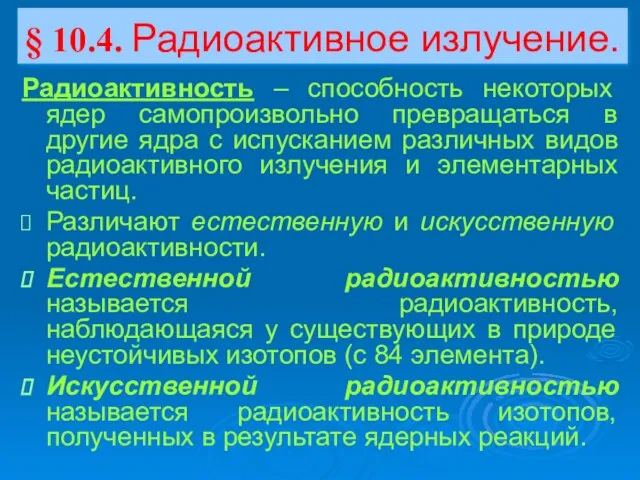 Презентация по физике Радиоактивное излучение
  Поляризація світла
 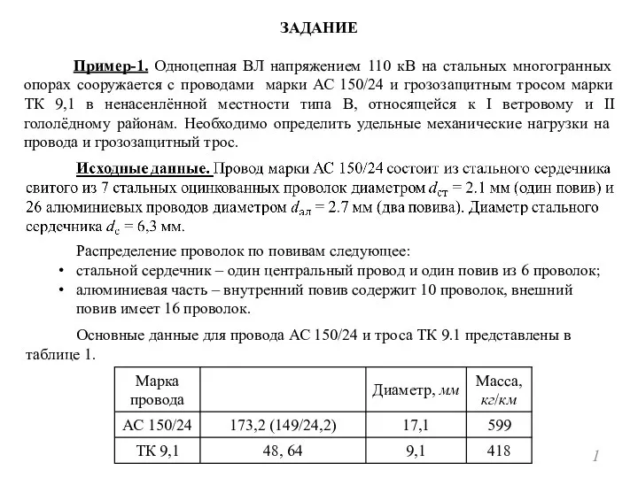 Одноцепная ВЛ напряжением 110 кВ на стальных многогранных опорах
 Основные положения спектроскопии
 Молекулярная физика и термодинамика. Подготовка к ЕГЭ
 Законы Нюьтона
 Конвекция. Основные положения переноса теплоты. (Тема 2. Лекции 6,7)
 Презентация по физике "Лауреаты Нобелевской премии по физике" - скачать
  Устройство преобразования частотного спектра звуковых сигналов
 Эквивалентные преобразования схем