- Estun Servo parameter adjustment methods

Содержание
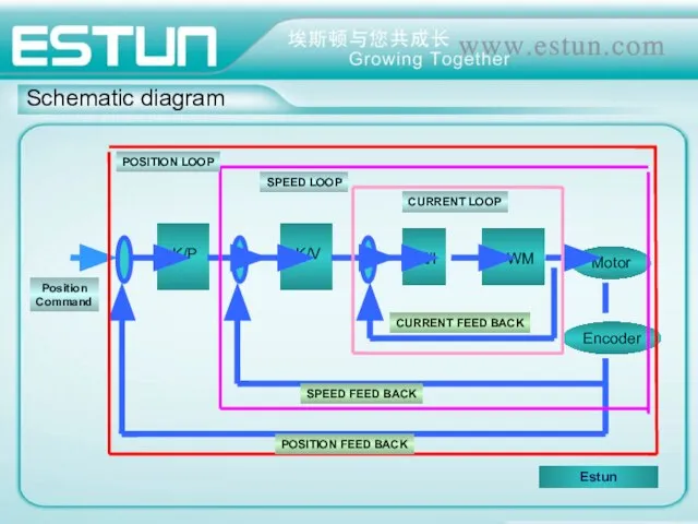
- 2. Schematic diagram
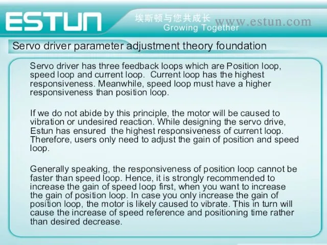
- 3. Servo driver parameter adjustment theory foundation Servo driver has three feedback loops which are Position loop,
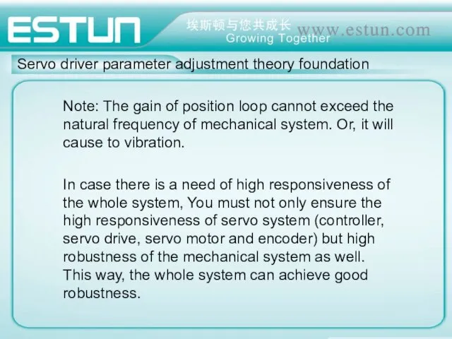
- 4. Servo driver parameter adjustment theory foundation Note: The gain of position loop cannot exceed the natural
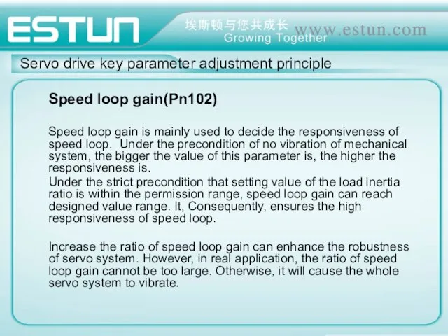
- 5. Servo drive key parameter adjustment principle Speed loop gain(Pn102) Speed loop gain is mainly used to
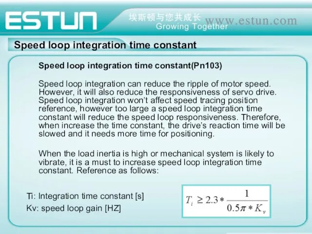
- 6. Speed loop integration time constant Speed loop integration time constant(Pn103) Speed loop integration can reduce the
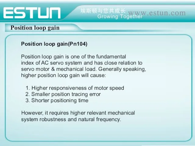
- 7. Position loop gain Position loop gain(Pn104) Position loop gain is one of the fundamental index of
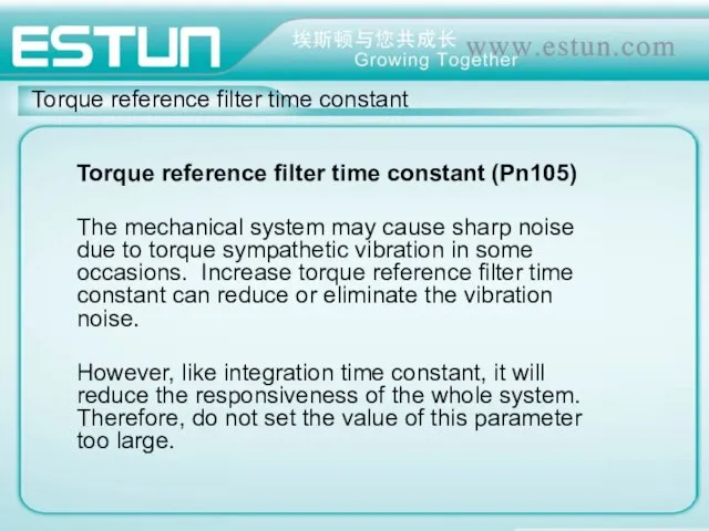
- 8. Torque reference filter time constant Torque reference filter time constant (Pn105) The mechanical system may cause
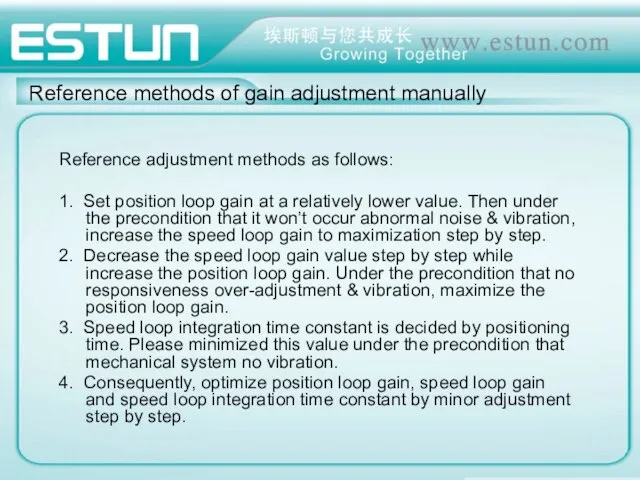
- 9. Reference methods of gain adjustment manually Reference adjustment methods as follows: 1. Set position loop gain
- 11. Скачать презентацию
Schematic diagram
Schematic diagram
Servo driver parameter adjustment theory foundation
Servo driver has three feedback loops
Servo driver parameter adjustment theory foundation
Servo driver has three feedback loops
Servo driver parameter adjustment theory foundation
Note: The gain of position loop
Servo driver parameter adjustment theory foundation
Note: The gain of position loop
Servo drive key parameter adjustment principle
Speed loop gain(Pn102)
Speed loop gain is
Servo drive key parameter adjustment principle
Speed loop gain(Pn102)
Speed loop gain is
Speed loop integration time constant
Speed loop integration time constant(Pn103)
Speed loop integration
Speed loop integration time constant
Speed loop integration time constant(Pn103)
Speed loop integration
Position loop gain
Position loop gain(Pn104)
Position loop gain is one of the
Position loop gain
Position loop gain(Pn104)
Position loop gain is one of the
Torque reference filter time constant
Torque reference filter time constant (Pn105)
The
Torque reference filter time constant
Torque reference filter time constant (Pn105)
The
Reference methods of gain adjustment manually
Reference adjustment methods as follows:
1. Set
Reference methods of gain adjustment manually
Reference adjustment methods as follows:
1. Set
 Верификация программного обеспечения. Виды тестирования
 Создание запросов в Access
 Состояние и перспективы развития информатики и ИТ
 Базы Данных
 Влияние интернета и компьютера на здоровье человека
 Задача: устранить ошибку Disk boot failure. Insert system disk and press enter
 Презентация "WEB-квесты" - скачать презентации по Информатике
 Развитие Алгоритмов шифрования
 Формы представления информации
 Функциональные возможности и решение практических задач
 Основные понятия системологии Системология – наука о системах Информатика 10 кл. учитель: Кирченко Людмила Владимировна
 Сравнительный анализ сред 3D моделирования
 Урок информатики 10 класс Тема «Размещение текстовой информации на форме при помощи управляющих элементов»
 Информационные ресурсы библиотеки
 Начало пути… Линейный алгоритм
 Adobe Lightroom
 Методы доступа и кадры сетей Ethernet, Token Ring, ArCNet, FDDI, WiFi
 Преимущества кластерного развития для регионального правительства, региональной промышленности
 Использование внешних устройств управления при разработке игр в визуальной среде программирования Scratch
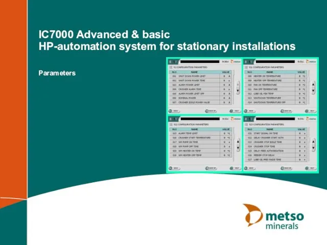 IC7000 Advanced & basic HP-automation system for stationary installations
 Елементи для введення даних: текстове поле, прапорець, випадаючий список
 Графики и диаграммы в Microsoft Office Excel
 Оформление текста ВКР и библиографии в соответствии с ГОСТ. Ссылки на источники 2017/18 учебный год
 Задача классификации. Метод деревьев решений
 Представление чисел в компьютере
 Услуги по защите от DDoS
 Аппаратная реализация компьютера
 Редактирование, добавление и удаление записей в таблице СУБД MySQL