- Network Layer: The Data Plane

Содержание
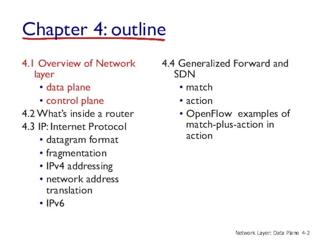
- 2. 4.1 Overview of Network layer data plane control plane 4.2 What’s inside a router 4.3 IP:
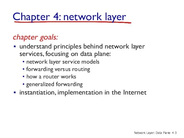
- 3. Chapter 4: network layer chapter goals: understand principles behind network layer services, focusing on data plane:
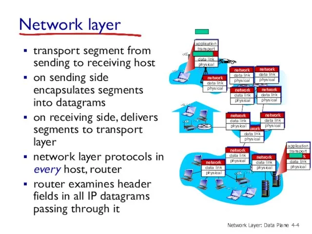
- 4. Network layer transport segment from sending to receiving host on sending side encapsulates segments into datagrams
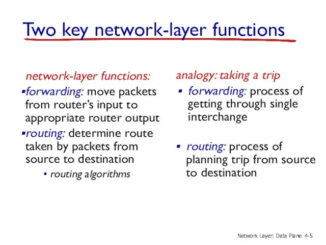
- 5. Two key network-layer functions network-layer functions: forwarding: move packets from router’s input to appropriate router output
- 6. Network layer: data plane, control plane Data plane local, per-router function determines how datagram arriving on
- 7. Per-router control plane Individual routing algorithm components in each and every router interact in the control
- 8. Logically centralized control plane A distinct (typically remote) controller interacts with local control agents (CAs) 5-
- 9. Network service model Q: What service model for “channel” transporting datagrams from sender to receiver? example
- 10. Network layer service models: Network Architecture Internet ATM ATM ATM ATM Service Model best effort CBR
- 11. 4.1 Overview of Network layer data plane control plane 4.2 What’s inside a router 4.3 IP:
- 12. Router architecture overview routing processor router input ports router output ports forwarding data plane (hardware) operttes
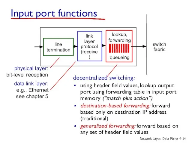
- 13. line termination link layer protocol (receive) lookup, forwarding queueing Input port functions decentralized switching: using header
- 14. line termination link layer protocol (receive) lookup, forwarding queueing Input port functions decentralized switching: using header
- 15. Destination Address Range 11001000 00010111 00010000 00000000 through 11001000 00010111 00010111 11111111 11001000 00010111 00011000 00000000
- 16. Longest prefix matching Destination Address Range 11001000 00010111 00010*** ********* 11001000 00010111 00011000 ********* 11001000 00010111
- 17. Longest prefix matching we’ll see why longest prefix matching is used shortly, when we study addressing
- 18. Switching fabrics transfer packet from input buffer to appropriate output buffer switching rate: rate at which
- 19. Switching via memory first generation routers: traditional computers with switching under direct control of CPU packet
- 20. Switching via a bus datagram from input port memory to output port memory via a shared
- 21. Switching via interconnection network overcome bus bandwidth limitations banyan networks, crossbar, other interconnection nets initially developed
- 22. Input port queuing fabric slower than input ports combined -> queueing may occur at input queues
- 23. Output ports buffering required when datagrams arrive from fabric faster than the transmission rate scheduling discipline
- 24. Output port queueing buffering when arrival rate via switch exceeds output line speed queueing (delay) and
- 25. How much buffering? RFC 3439 rule of thumb: average buffering equal to “typical” RTT (say 250
- 26. Scheduling mechanisms scheduling: choose next packet to send on link FIFO (first in first out) scheduling:
- 27. Scheduling policies: priority priority scheduling: send highest priority queued packet multiple classes, with different priorities class
- 28. Scheduling policies: still more Round Robin (RR) scheduling: multiple classes cyclically scan class queues, sending one
- 29. Weighted Fair Queuing (WFQ): generalized Round Robin each class gets weighted amount of service in each
- 30. 4.1 Overview of Network layer data plane control plane 4.2 What’s inside a router 4.3 IP:
- 31. The Internet network layer host, router network layer functions: routing protocols path selection RIP, OSPF, BGP
- 32. IP datagram format how much overhead? 20 bytes of TCP 20 bytes of IP = 40
- 33. IP fragmentation, reassembly network links have MTU (max.transfer size) - largest possible link-level frame different link
- 34. example: 4000 byte datagram MTU = 1500 bytes 1480 bytes in data field offset = 1480/8
- 35. 4.1 Overview of Network layer data plane control plane 4.2 What’s inside a router 4.3 IP:
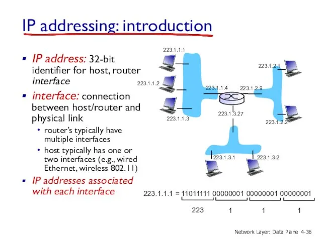
- 36. IP addressing: introduction IP address: 32-bit identifier for host, router interface interface: connection between host/router and
- 37. IP addressing: introduction Q: how are interfaces actually connected? A: we’ll learn about that in chapter
- 38. Subnets IP address: subnet part - high order bits host part - low order bits what’s
- 39. recipe to determine the subnets, detach each interface from its host or router, creating islands of
- 40. how many? 223.1.1.1 223.1.1.3 223.1.1.4 223.1.2.2 223.1.2.1 223.1.2.6 223.1.3.2 223.1.3.1 223.1.3.27 223.1.1.2 223.1.7.0 223.1.7.1 223.1.8.0 223.1.8.1
- 41. IP addressing: CIDR CIDR: Classless InterDomain Routing subnet portion of address of arbitrary length address format:
- 42. IP addresses: how to get one? Q: How does a host get IP address? hard-coded by
- 43. DHCP: Dynamic Host Configuration Protocol goal: allow host to dynamically obtain its IP address from network
- 44. DHCP client-server scenario 223.1.1.0/24 223.1.2.0/24 223.1.3.0/24 223.1.1.1 223.1.1.3 223.1.1.4 223.1.2.9 223.1.3.2 223.1.3.1 223.1.1.2 223.1.3.27 223.1.2.2 223.1.2.1
- 45. DHCP server: 223.1.2.5 arriving client DHCP client-server scenario 4- Network Layer: Data Plane
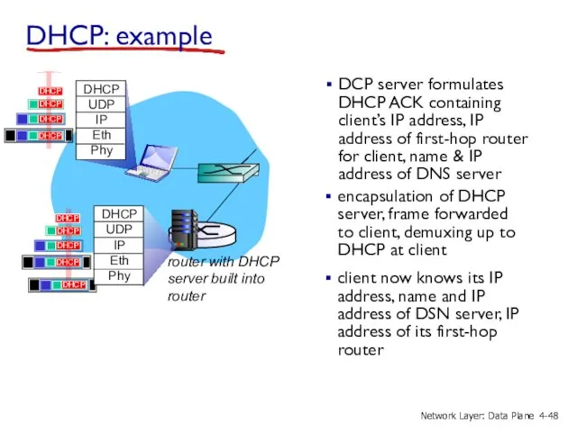
- 46. DHCP: more than IP addresses DHCP can return more than just allocated IP address on subnet:
- 47. connecting laptop needs its IP address, addr of first-hop router, addr of DNS server: use DHCP
- 48. DCP server formulates DHCP ACK containing client’s IP address, IP address of first-hop router for client,
- 49. DHCP: Wireshark output (home LAN) Message type: Boot Reply (2) Hardware type: Ethernet Hardware address length:
- 50. IP addresses: how to get one? Q: how does network get subnet part of IP addr?
- 51. Hierarchical addressing: route aggregation “Send me anything with addresses beginning 200.23.16.0/20” Fly-By-Night-ISP Organization 0 Organization 7
- 52. ISPs-R-Us has a more specific route to Organization 1 “Send me anything with addresses beginning 200.23.16.0/20”
- 53. IP addressing: the last word... Q: how does an ISP get block of addresses? A: ICANN:
- 54. NAT: network address translation 10.0.0.1 10.0.0.2 10.0.0.3 10.0.0.4 138.76.29.7 local network (e.g., home network) 10.0.0/24 rest
- 55. motivation: local network uses just one IP address as far as outside world is concerned: range
- 56. implementation: NAT router must: outgoing datagrams: replace (source IP address, port #) of every outgoing datagram
- 57. 10.0.0.1 10.0.0.2 10.0.0.3 10.0.0.4 138.76.29.7 NAT translation table WAN side addr LAN side addr 138.76.29.7, 5001
- 58. 16-bit port-number field: 60,000 simultaneous connections with a single LAN-side address! NAT is controversial: routers should
- 59. 4.1 Overview of Network layer data plane control plane 4.2 What’s inside a router 4.3 IP:
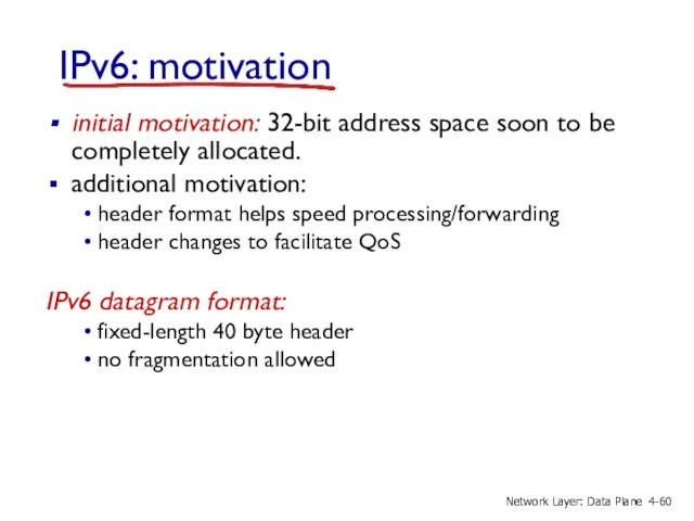
- 60. IPv6: motivation initial motivation: 32-bit address space soon to be completely allocated. additional motivation: header format
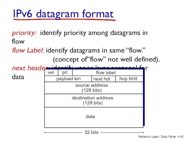
- 61. IPv6 datagram format priority: identify priority among datagrams in flow flow Label: identify datagrams in same
- 62. Other changes from IPv4 checksum: removed entirely to reduce processing time at each hop options: allowed,
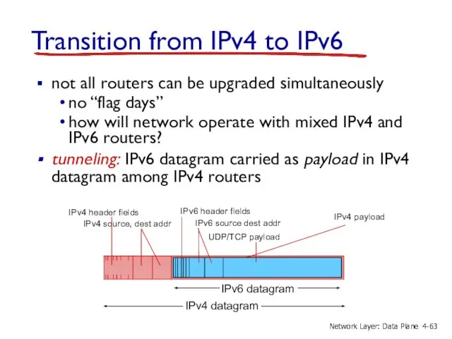
- 63. Transition from IPv4 to IPv6 not all routers can be upgraded simultaneously no “flag days” how
- 64. Tunneling physical view: IPv4 IPv4 C D 4- Network Layer: Data Plane
- 65. physical view: C D Tunneling IPv4 IPv4 4- Network Layer: Data Plane
- 66. IPv6: adoption Google: 8% of clients access services via IPv6 NIST: 1/3 of all US government
- 67. 4.1 Overview of Network layer data plane control plane 4.2 What’s inside a router 4.3 IP:
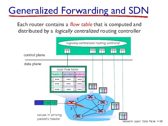
- 68. Generalized Forwarding and SDN 2 3 0100 1101 values in arriving packet’s header 1 control plane
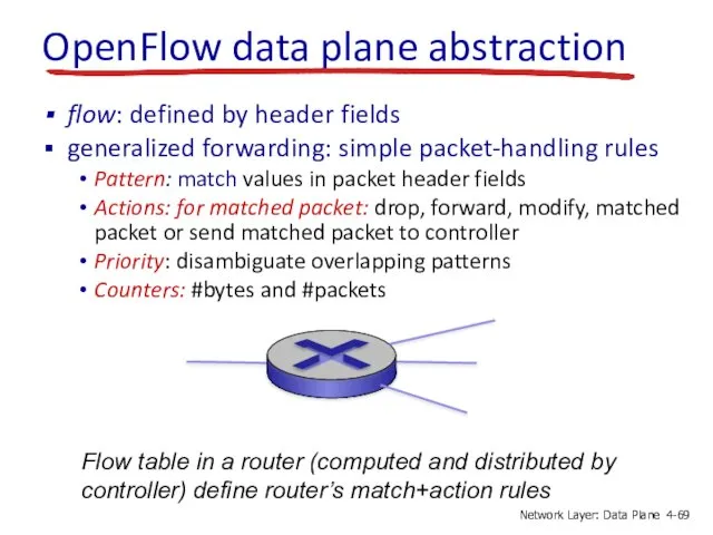
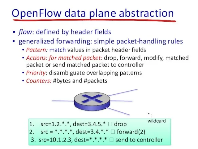
- 69. OpenFlow data plane abstraction flow: defined by header fields generalized forwarding: simple packet-handling rules Pattern: match
- 70. OpenFlow data plane abstraction flow: defined by header fields generalized forwarding: simple packet-handling rules Pattern: match
- 71. OpenFlow: Flow Table Entries Switch Port MAC src MAC dst Eth type VLAN ID IP Src
- 72. Destination-based forwarding: * * * * * * 51.6.0.8 * * * port6 Examples IP datagrams
- 73. Destination-based layer 2 (switch) forwarding: * * * * * * * * * port3 Examples
- 74. OpenFlow abstraction Router match: longest destination IP prefix action: forward out a link Switch match: destination
- 75. OpenFlow example Host h1 10.1.0.1 Host h2 10.1.0.2 Host h4 10.2.0.4 Host h3 10.2.0.3 Host h5
- 77. Скачать презентацию
4.1 Overview of Network layer
data plane
control plane
4.2 What’s inside a router
4.3
4.1 Overview of Network layer
data plane
control plane
4.2 What’s inside a router
4.3
Chapter 4: network layer
chapter goals:
understand principles behind network layer services,
Chapter 4: network layer
chapter goals:
understand principles behind network layer services,
Network layer
transport segment from sending to receiving host
on sending side
Network layer
transport segment from sending to receiving host
on sending side
Two key network-layer functions
network-layer functions:
forwarding: move packets from router’s input to
Two key network-layer functions
network-layer functions:
forwarding: move packets from router’s input to
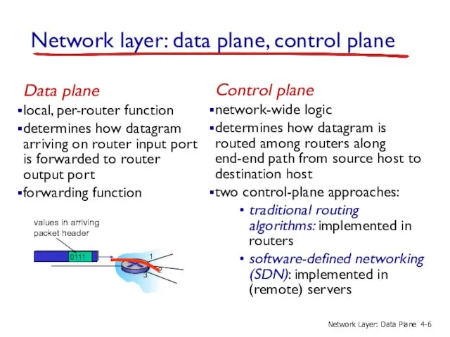
Network layer: data plane, control plane
Data plane
local, per-router function
determines how datagram
Network layer: data plane, control plane
Data plane
local, per-router function
determines how datagram
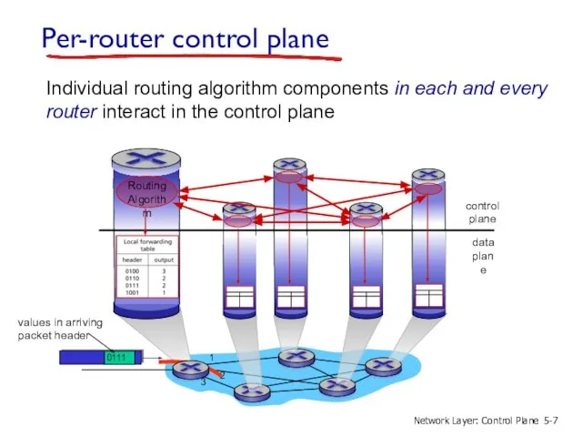
Per-router control plane
Individual routing algorithm components in each and every router
Per-router control plane
Individual routing algorithm components in each and every router
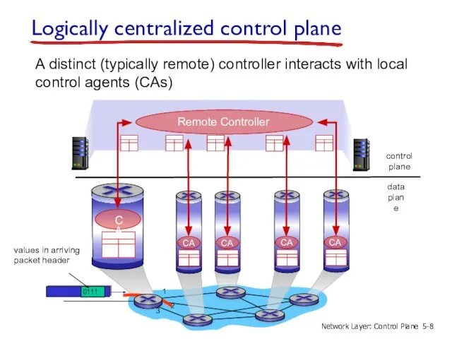
Logically centralized control plane
A distinct (typically remote) controller interacts with local
Logically centralized control plane
A distinct (typically remote) controller interacts with local
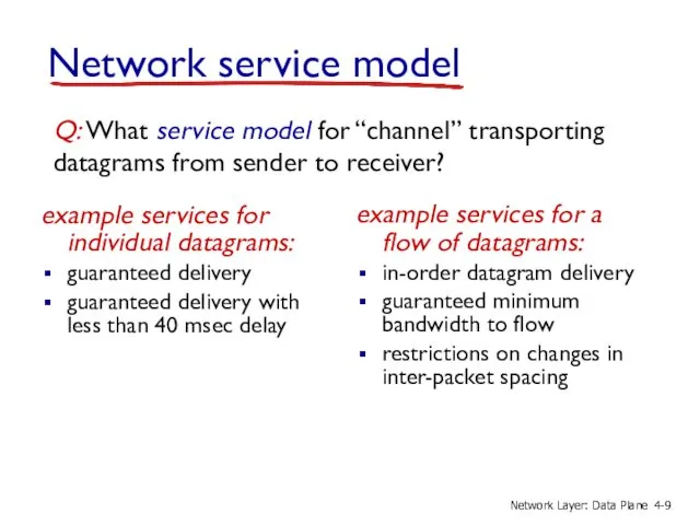
Network service model
Q: What service model for “channel” transporting datagrams from
Network service model
Q: What service model for “channel” transporting datagrams from
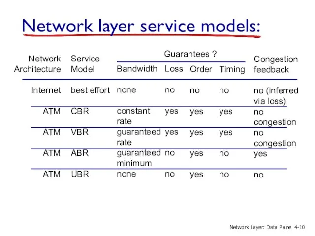
Network layer service models:
Network
Architecture
Internet
ATM
ATM
ATM
ATM
Service
Model
best effort
CBR
VBR
ABR
UBR
Bandwidth
none
constant
rate
guaranteed
rate
guaranteed
minimum
none
Loss
no
yes
yes
no
no
Order
no
yes
yes
yes
yes
Timing
no
yes
yes
no
no
Congestion
feedback
no (inferred
via loss)
no
congestion
no
congestion
yes
no
Guarantees ?
4-
Network Layer: Data
4.1 Overview of Network layer
data plane
control plane
4.2 What’s inside a router
4.3
4.1 Overview of Network layer
data plane
control plane
4.2 What’s inside a router
4.3
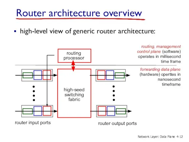
Router architecture overview
routing
processor
router input ports
router output ports
forwarding data plane (hardware)
Router architecture overview
routing
processor
router input ports
router output ports
forwarding data plane (hardware)
line
termination
link
layer
protocol
(receive)
lookup,
forwarding
queueing
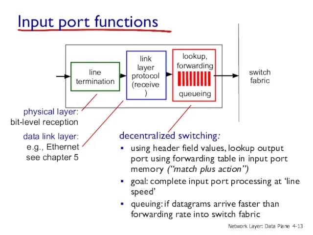
Input port functions
decentralized switching:
using header field values, lookup
line
termination
link
layer
protocol
(receive)
lookup,
forwarding
queueing
Input port functions
decentralized switching:
using header field values, lookup
line
termination
link
layer
protocol
(receive)
lookup,
forwarding
queueing
Input port functions
decentralized switching:
using header field values, lookup
line
termination
link
layer
protocol
(receive)
lookup,
forwarding
queueing
Input port functions
decentralized switching:
using header field values, lookup
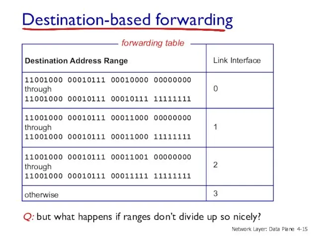
Destination Address Range
11001000 00010111 00010000 00000000
through
11001000 00010111 00010111 11111111
11001000 00010111
Destination Address Range
11001000 00010111 00010000 00000000
through
11001000 00010111 00010111 11111111
11001000 00010111
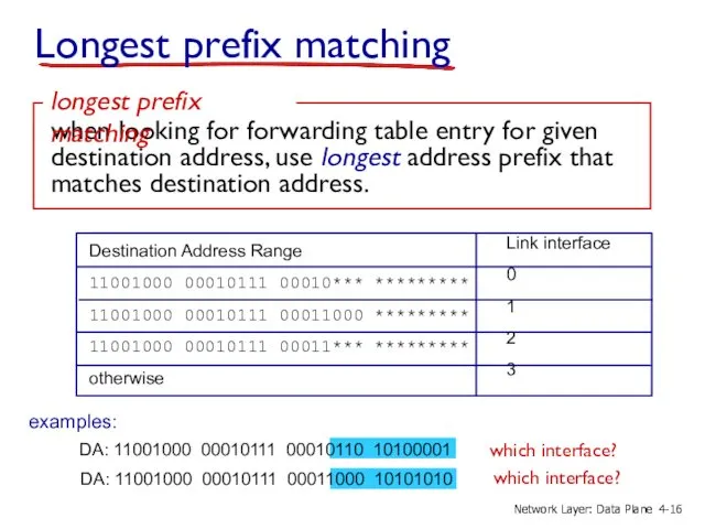
Longest prefix matching
Destination Address Range
11001000 00010111 00010*** *********
11001000 00010111
Longest prefix matching
Destination Address Range
11001000 00010111 00010*** *********
11001000 00010111
Longest prefix matching
we’ll see why longest prefix matching is used shortly,
Longest prefix matching
we’ll see why longest prefix matching is used shortly,
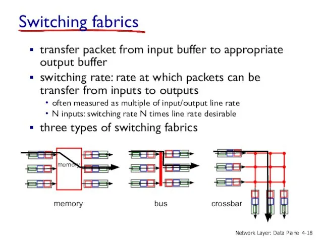
Switching fabrics
transfer packet from input buffer to appropriate output buffer
switching rate:
Switching fabrics
transfer packet from input buffer to appropriate output buffer
switching rate:
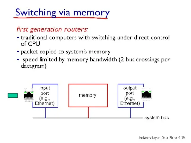
Switching via memory
first generation routers:
traditional computers with switching under direct control
Switching via memory
first generation routers:
traditional computers with switching under direct control

Switching via a bus
datagram from input port memory
to output port
Switching via a bus
datagram from input port memory
to output port
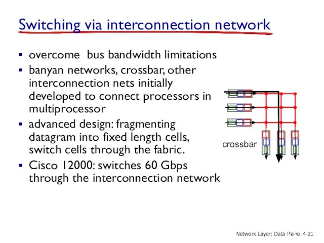
Switching via interconnection network
overcome bus bandwidth limitations
banyan networks, crossbar, other interconnection
Switching via interconnection network
overcome bus bandwidth limitations
banyan networks, crossbar, other interconnection
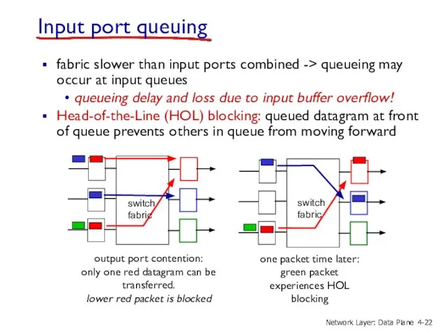
Input port queuing
fabric slower than input ports combined -> queueing may
Input port queuing
fabric slower than input ports combined -> queueing may
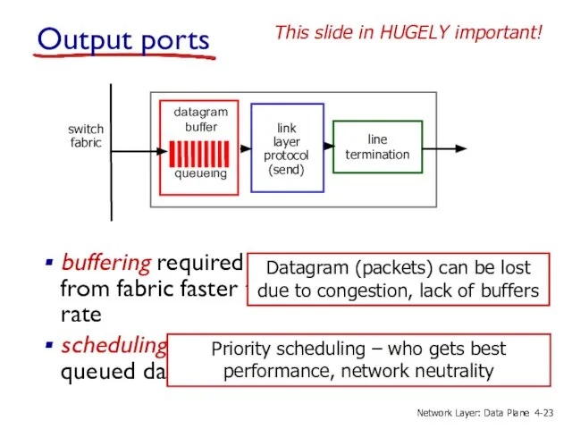
Output ports
buffering required when datagrams arrive from fabric faster than the
Output ports
buffering required when datagrams arrive from fabric faster than the
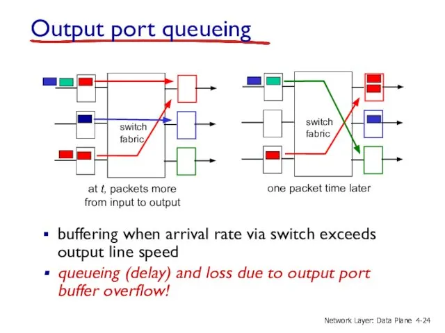
Output port queueing
buffering when arrival rate via switch exceeds output line
Output port queueing
buffering when arrival rate via switch exceeds output line
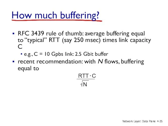
How much buffering?
RFC 3439 rule of thumb: average buffering equal to
How much buffering?
RFC 3439 rule of thumb: average buffering equal to
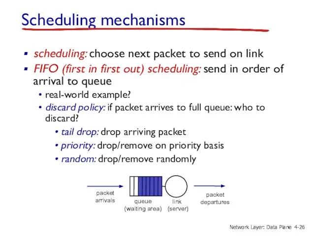
Scheduling mechanisms
scheduling: choose next packet to send on link
FIFO (first in
Scheduling mechanisms
scheduling: choose next packet to send on link
FIFO (first in
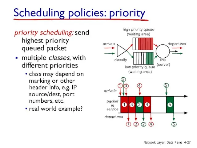
Scheduling policies: priority
priority scheduling: send highest priority queued packet
multiple classes,
Scheduling policies: priority
priority scheduling: send highest priority queued packet
multiple classes,
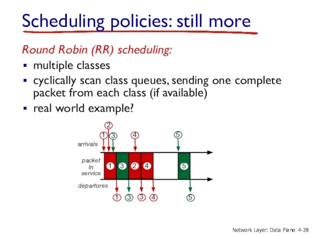
Scheduling policies: still more
Round Robin (RR) scheduling:
multiple classes
cyclically scan class queues,
Scheduling policies: still more
Round Robin (RR) scheduling:
multiple classes
cyclically scan class queues,
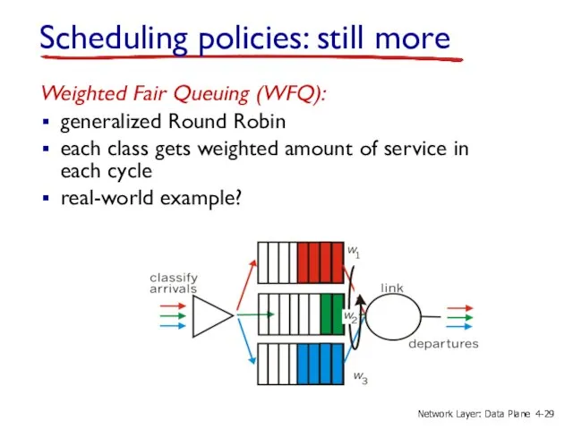
Weighted Fair Queuing (WFQ):
generalized Round Robin
each class gets weighted amount
Weighted Fair Queuing (WFQ):
generalized Round Robin
each class gets weighted amount
4.1 Overview of Network layer
data plane
control plane
4.2 What’s inside a router
4.3
4.1 Overview of Network layer
data plane
control plane
4.2 What’s inside a router
4.3
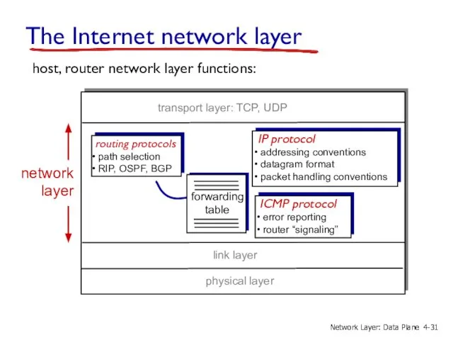
The Internet network layer
host, router network layer functions:
routing protocols
path selection
The Internet network layer
host, router network layer functions:
routing protocols
path selection
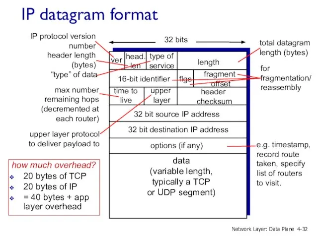
IP datagram format
how much overhead?
20 bytes of TCP
20 bytes of IP
=
IP datagram format
how much overhead?
20 bytes of TCP
20 bytes of IP
=
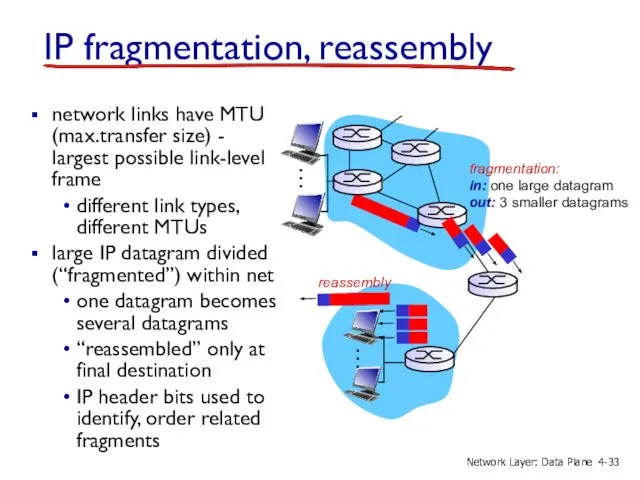
IP fragmentation, reassembly
network links have MTU (max.transfer size) - largest possible
IP fragmentation, reassembly
network links have MTU (max.transfer size) - largest possible
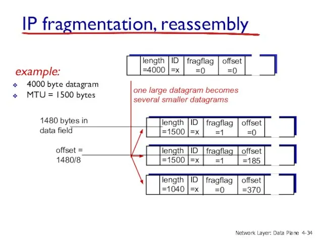
example:
4000 byte datagram
MTU = 1500 bytes
1480 bytes in
data field
offset =
1480/8
example:
4000 byte datagram
MTU = 1500 bytes
1480 bytes in
data field
offset =
1480/8

4.1 Overview of Network layer
data plane
control plane
4.2 What’s inside a router
4.3
4.1 Overview of Network layer
data plane
control plane
4.2 What’s inside a router
4.3
IP addressing: introduction
IP address: 32-bit identifier for host, router interface
interface:
IP addressing: introduction
IP address: 32-bit identifier for host, router interface
interface:
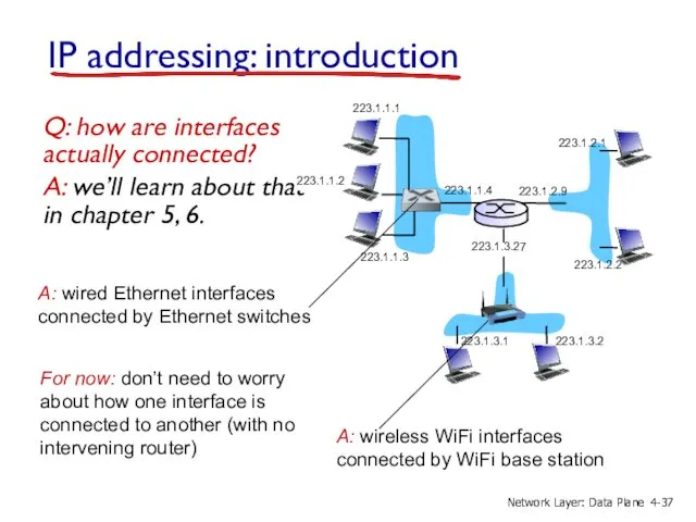
IP addressing: introduction
Q: how are interfaces actually connected?
A: we’ll learn about
IP addressing: introduction
Q: how are interfaces actually connected?
A: we’ll learn about
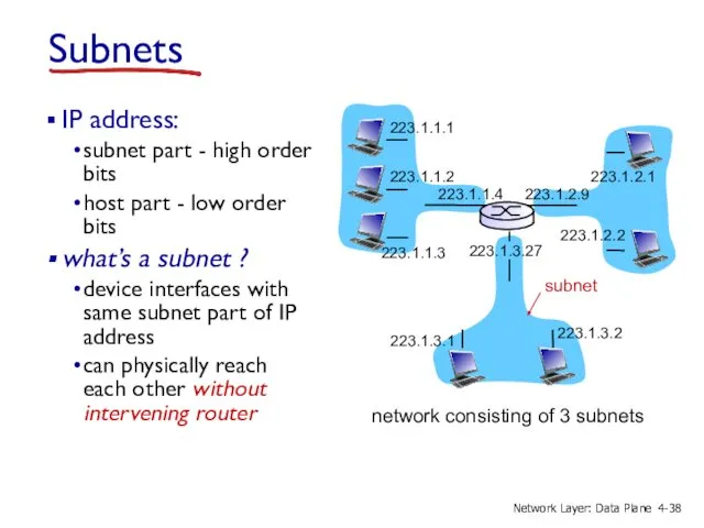
Subnets
IP address:
subnet part - high order bits
host part - low
Subnets
IP address:
subnet part - high order bits
host part - low
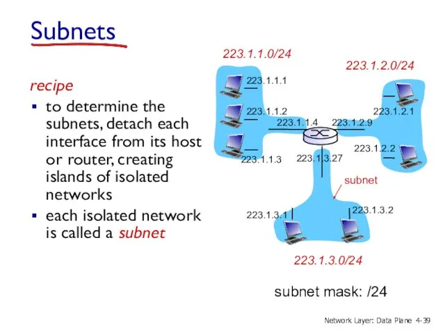
recipe
to determine the subnets, detach each interface from its host or
recipe
to determine the subnets, detach each interface from its host or
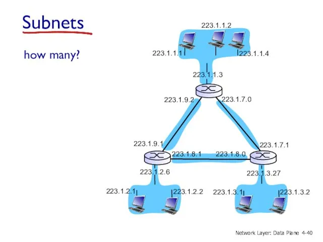
how many?
223.1.1.1
223.1.1.3
223.1.1.4
223.1.2.2
223.1.2.1
223.1.2.6
223.1.3.2
223.1.3.1
223.1.3.27
223.1.1.2
223.1.7.0
223.1.7.1
223.1.8.0
223.1.8.1
223.1.9.1
223.1.9.2
Subnets
4-
Network Layer: Data Plane
how many?
223.1.1.1
223.1.1.3
223.1.1.4
223.1.2.2
223.1.2.1
223.1.2.6
223.1.3.2
223.1.3.1
223.1.3.27
223.1.1.2
223.1.7.0
223.1.7.1
223.1.8.0
223.1.8.1
223.1.9.1
223.1.9.2
Subnets
4-
Network Layer: Data Plane
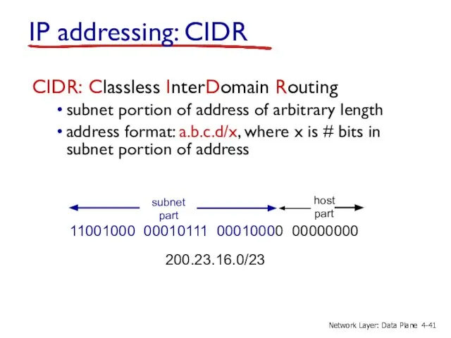
IP addressing: CIDR
CIDR: Classless InterDomain Routing
subnet portion of address of arbitrary
IP addressing: CIDR
CIDR: Classless InterDomain Routing
subnet portion of address of arbitrary
IP addresses: how to get one?
Q: How does a host get
IP addresses: how to get one?
Q: How does a host get
DHCP: Dynamic Host Configuration Protocol
goal: allow host to dynamically obtain its
DHCP: Dynamic Host Configuration Protocol
goal: allow host to dynamically obtain its
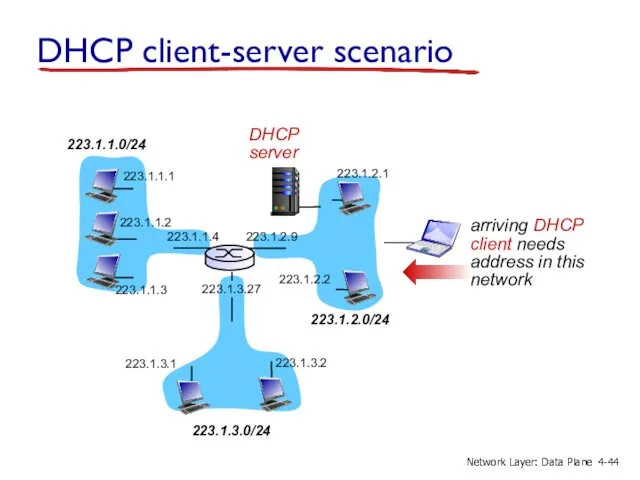
DHCP client-server scenario
223.1.1.0/24
223.1.2.0/24
223.1.3.0/24
223.1.1.1
223.1.1.3
223.1.1.4
223.1.2.9
223.1.3.2
223.1.3.1
223.1.1.2
223.1.3.27
223.1.2.2
223.1.2.1
DHCP
server
arriving DHCP
client needs
address in this
network
4-
Network Layer: Data Plane
DHCP client-server scenario
223.1.1.0/24
223.1.2.0/24
223.1.3.0/24
223.1.1.1
223.1.1.3
223.1.1.4
223.1.2.9
223.1.3.2
223.1.3.1
223.1.1.2
223.1.3.27
223.1.2.2
223.1.2.1
DHCP
server
arriving DHCP
client needs
address in this
network
4-
Network Layer: Data Plane
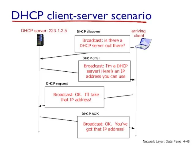
DHCP server: 223.1.2.5
arriving
client
DHCP client-server scenario
4-
Network Layer: Data Plane
DHCP server: 223.1.2.5
arriving
client
DHCP client-server scenario
4-
Network Layer: Data Plane
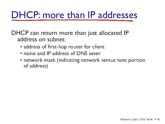
DHCP: more than IP addresses
DHCP can return more than just allocated
DHCP: more than IP addresses
DHCP can return more than just allocated
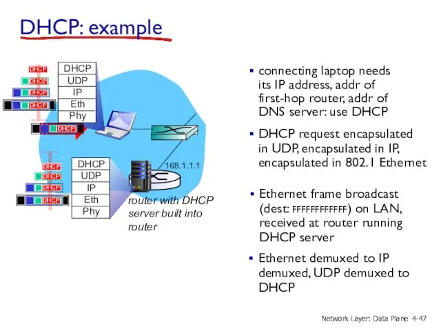
connecting laptop needs its IP address, addr of first-hop router, addr
connecting laptop needs its IP address, addr of first-hop router, addr
DCP server formulates DHCP ACK containing client’s IP address, IP address
DCP server formulates DHCP ACK containing client’s IP address, IP address
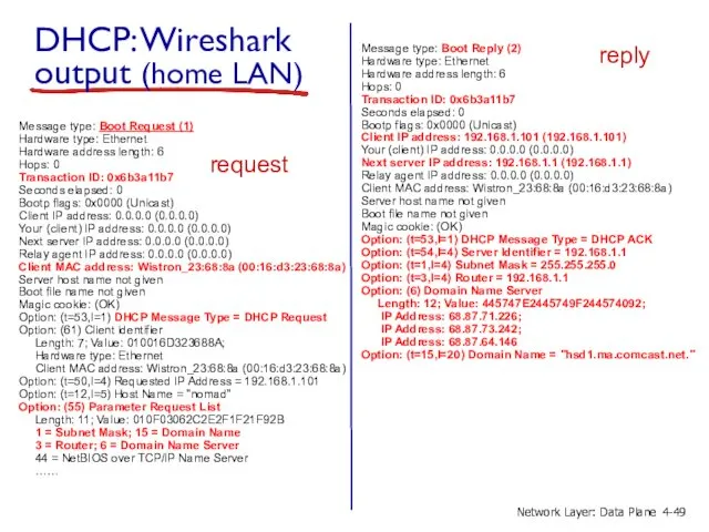
DHCP: Wireshark output (home LAN)
Message type: Boot Reply (2)
Hardware type: Ethernet
Hardware
DHCP: Wireshark output (home LAN)
Message type: Boot Reply (2)
Hardware type: Ethernet
Hardware
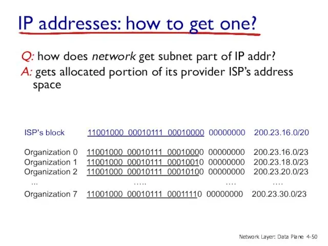
IP addresses: how to get one?
Q: how does network get subnet
IP addresses: how to get one?
Q: how does network get subnet
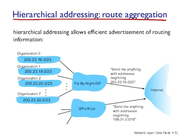
Hierarchical addressing: route aggregation
“Send me anything
with addresses
beginning
200.23.16.0/20”
Fly-By-Night-ISP
Organization 0
Organization 7
Internet
Organization
Hierarchical addressing: route aggregation
“Send me anything
with addresses
beginning
200.23.16.0/20”
Fly-By-Night-ISP
Organization 0
Organization 7
Internet
Organization
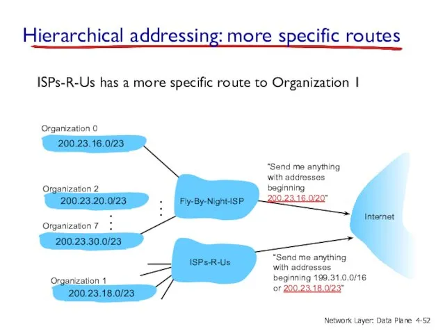
ISPs-R-Us has a more specific route to Organization 1
“Send me anything
with
ISPs-R-Us has a more specific route to Organization 1
“Send me anything
with
IP addressing: the last word...
Q: how does an ISP get block
IP addressing: the last word...
Q: how does an ISP get block
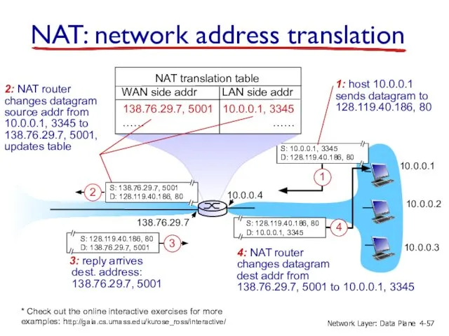
NAT: network address translation
10.0.0.1
10.0.0.2
10.0.0.3
10.0.0.4
138.76.29.7
local network
(e.g., home network)
10.0.0/24
rest of
Internet
datagrams with source or
NAT: network address translation
10.0.0.1
10.0.0.2
10.0.0.3
10.0.0.4
138.76.29.7
local network
(e.g., home network)
10.0.0/24
rest of
Internet
datagrams with source or
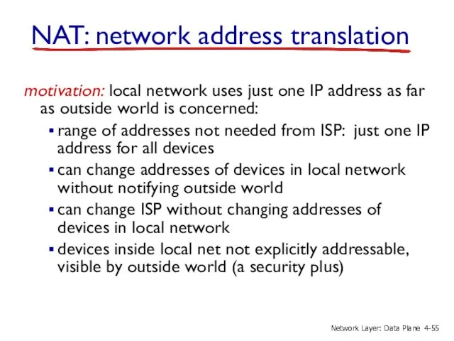
motivation: local network uses just one IP address as far as
motivation: local network uses just one IP address as far as
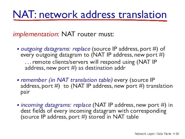
implementation: NAT router must:
outgoing datagrams: replace (source IP address, port
implementation: NAT router must:
outgoing datagrams: replace (source IP address, port
10.0.0.1
10.0.0.2
10.0.0.3
10.0.0.4
138.76.29.7
NAT translation table
WAN side addr LAN side addr
138.76.29.7, 5001 10.0.0.1, 3345
……
10.0.0.1
10.0.0.2
10.0.0.3
10.0.0.4
138.76.29.7
NAT translation table
WAN side addr LAN side addr
138.76.29.7, 5001 10.0.0.1, 3345
……
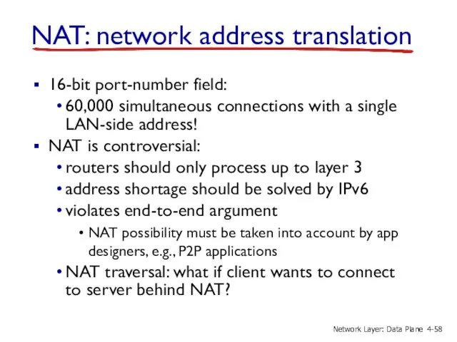
16-bit port-number field:
60,000 simultaneous connections with a single LAN-side address!
NAT
16-bit port-number field:
60,000 simultaneous connections with a single LAN-side address!
NAT
4.1 Overview of Network layer
data plane
control plane
4.2 What’s inside a router
4.3
4.1 Overview of Network layer
data plane
control plane
4.2 What’s inside a router
4.3
IPv6: motivation
initial motivation: 32-bit address space soon to be completely allocated.
IPv6: motivation
initial motivation: 32-bit address space soon to be completely allocated.
IPv6 datagram format
priority: identify priority among datagrams in flow
flow Label: identify
IPv6 datagram format
priority: identify priority among datagrams in flow
flow Label: identify
Other changes from IPv4
checksum: removed entirely to reduce processing time at
Other changes from IPv4
checksum: removed entirely to reduce processing time at
Transition from IPv4 to IPv6
not all routers can be upgraded simultaneously
no
Transition from IPv4 to IPv6
not all routers can be upgraded simultaneously
no
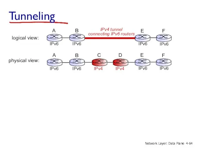
Tunneling
physical view:
IPv4
IPv4
C
D
4-
Network Layer: Data Plane
Tunneling
physical view:
IPv4
IPv4
C
D
4-
Network Layer: Data Plane
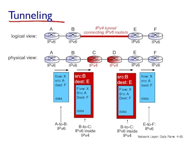
physical view:
C
D
Tunneling
IPv4
IPv4
4-
Network Layer: Data Plane
physical view:
C
D
Tunneling
IPv4
IPv4
4-
Network Layer: Data Plane
IPv6: adoption
Google: 8% of clients access services via IPv6
NIST: 1/3 of
IPv6: adoption
Google: 8% of clients access services via IPv6
NIST: 1/3 of
4.1 Overview of Network layer
data plane
control plane
4.2 What’s inside a router
4.3
4.1 Overview of Network layer
data plane
control plane
4.2 What’s inside a router
4.3
Generalized Forwarding and SDN
2
3
0100 1101
values in arriving
packet’s header
1
control plane
data plane
Each router
Generalized Forwarding and SDN
2
3
0100 1101
values in arriving
packet’s header
1
control plane
data plane
Each router
OpenFlow data plane abstraction
flow: defined by header fields
generalized forwarding: simple packet-handling
OpenFlow data plane abstraction
flow: defined by header fields
generalized forwarding: simple packet-handling
OpenFlow data plane abstraction
flow: defined by header fields
generalized forwarding: simple packet-handling
OpenFlow data plane abstraction
flow: defined by header fields
generalized forwarding: simple packet-handling
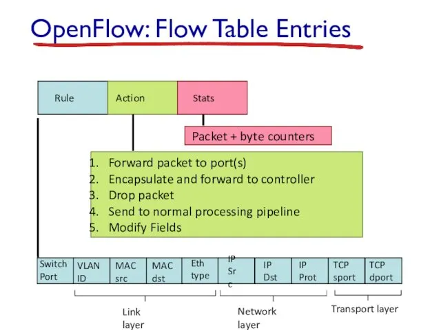
OpenFlow: Flow Table Entries
Switch
Port
MAC
src
MAC
dst
Eth
type
VLAN
ID
IP
Src
IP
Dst
IP
Prot
TCP
sport
TCP
dport
Rule
Action
Stats
Forward packet to port(s)
Encapsulate and forward to controller
Drop
OpenFlow: Flow Table Entries
Switch
Port
MAC
src
MAC
dst
Eth
type
VLAN
ID
IP
Src
IP
Dst
IP
Prot
TCP
sport
TCP
dport
Rule
Action
Stats
Forward packet to port(s)
Encapsulate and forward to controller
Drop
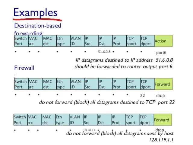
Destination-based forwarding:
*
*
*
*
*
*
51.6.0.8
*
*
*
port6
Examples
IP datagrams destined to IP address 51.6.0.8 should be forwarded
Destination-based forwarding:
*
*
*
*
*
*
51.6.0.8
*
*
*
port6
Examples
IP datagrams destined to IP address 51.6.0.8 should be forwarded
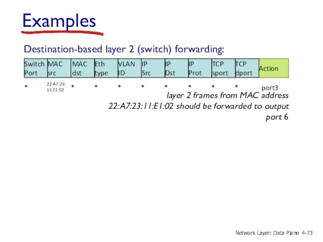
Destination-based layer 2 (switch) forwarding:
*
*
*
*
*
*
*
*
*
port3
Examples
layer 2 frames from MAC address 22:A7:23:11:E1:02
Destination-based layer 2 (switch) forwarding:
*
*
*
*
*
*
*
*
*
port3
Examples
layer 2 frames from MAC address 22:A7:23:11:E1:02
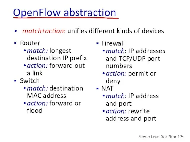
OpenFlow abstraction
Router
match: longest destination IP prefix
action: forward out a link
Switch
match: destination
OpenFlow abstraction
Router
match: longest destination IP prefix
action: forward out a link
Switch
match: destination
OpenFlow example
Host h1
10.1.0.1
Host h2
10.1.0.2
Host h4
10.2.0.4
Host h3
10.2.0.3
Host h5
10.3.0.5
s1
s2
s3
1
2
3
4
1
2
3
4
1
2
3
4
Host h6
10.3.0.6
Example: datagrams from hosts
OpenFlow example
Host h1
10.1.0.1
Host h2
10.1.0.2
Host h4
10.2.0.4
Host h3
10.2.0.3
Host h5
10.3.0.5
s1
s2
s3
1
2
3
4
1
2
3
4
1
2
3
4
Host h6
10.3.0.6
Example: datagrams from hosts
 Построение диаграмм в электронных таблицах. 8 класс
 Восьмиричная и шестнадцатиричная системы счисления
 Программа UniversalBkon
 Инвестиционная идея. Мобильное приложение
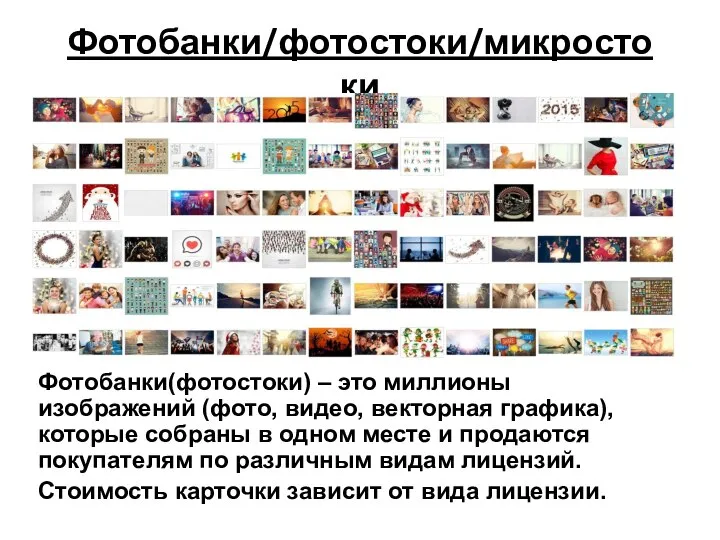 Фотобанки/фотостоки/микростоки
 Презентация "День безопасного Рунета" - скачать презентации по Информатике
 sredstva_zaschity_informatsii
 LGE Internal Use Only
 Безопасность в сети Интернет
  Презентация "Программирование как этап решения задачи на компьютере" - скачать презентации по Информатике
 Исполнители вокруг нас
 Теория информации
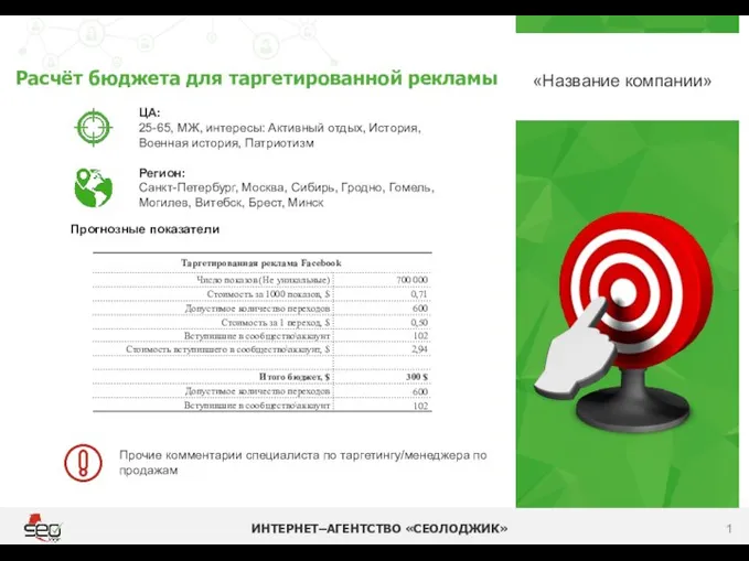 Раcчёт бюджета для таргетированной рекламы
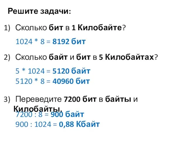 Задачи на количество информации
 Цифровая sim-карта
 Выполнила: Кормина Ирина 10 класс.
 Створення банку ідей. (10 клас)
 Презентация "ДЕЙСТВИЕ С ИНФОРМАЦИЕЙ. ХРАНЕНИЕ ИНФОРМАЦИИ" - скачать презентации по Информатике
 Специфика печати, радио, телевидения и Интернета как разновидностей СМИ
 Онлайн-диалог. Сервис для оперативного поиска информации и документов
 Муниципальное общеобразовательное учреждение гимназия №1 Учитель информатики: Скабёлкина М.Ю. Липецк 2011 8 класс
 Деректер базасының архитектурасы
 Устройства ввода и вывода информации. 8 класс
 Data Scientist. Рекомендательные системы
 MEL Scripting & Maya’s C++ API
 Информационные системы
 Использование интернет-ресурсов в продвижении имиджевых event-проектов
 Понятие «Алгоритм» и Формы его записи. Исполнители алгоритмов